Repair and decoration
04/19/2018 Anastasia Prozheva
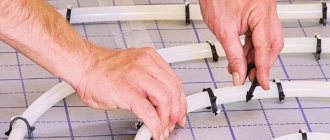
Today there are quite a large number of different autonomous heating systems. Each of them has its own advantages and disadvantages. One of the corners that ensures the efficiency and performance of a heating system is the manifold. Assembling such a structure for a heated floor with your own hands is quite simple if you know the layout of the collector and understand how it should work.
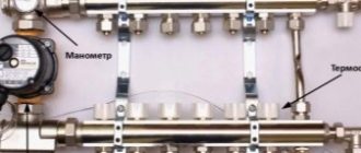
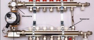
Manifold diagram for heated floors.
The collector is a node that includes the following elements:
- pipes that are made of plastic or metal;
- valves;
- pressure gauges;
- valves;
- fitting;
- other auxiliary units.
How does a collector work and what is it for?
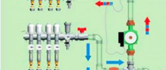
An example of connecting a heated floor collector.
The design is used to mix the coolant that comes from various heating circuits. Subsequently, the device distributes the coolant along these circuits. By mixing, the temperature of the liquid will equalize. Therefore, the temperature in rooms that are heated will be stable.
You should know that the quality of the floor heating system will depend on the correct assembly of the collector structure.
The operating principle of the heating system is as follows: the hot coolant, after passing through existing circuits and pipes, will cool down, and under the action of the pumping structure or natural circulation will flow back into the collector. In this element, the coolant is mixed through a return pipe. The proportions of hot and cooled coolant can be adjusted by valves. Temperature control is carried out using special heat and pressure sensors. If the heating system is too long or there is no possibility of natural circulation in the house, then a circulation pump will need to be included in the collector structure.
A standard manifold consists of the following elements:
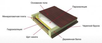
Diagram of a water heated floor.
- two-way or three-way mixing valve;
- shut-off valves;
- balancing valves;
- temperature sensor;
- pressure gauge;
- circulation pump;
- element for automatic air exhaust;
- fitting;
- tees;
- adapters;
- nipples.
You will also need some other elements for installation.
The design functions as follows: if the temperature exceeds a certain value, the thermal head will close the valve, and a small amount of hot coolant will be supplied. As the coolant cools, the valve will supply more liquid. The heat carrier is supplied from the return pipe with a continuous pressure, and from the supply pipe - if necessary. Consequently, the average temperature of the liquid will remain constant.
Related article: Silverfish appeared in the bathroom: how to get rid of it?
Mixing valves
Depending on the desired effect, there are various connection methods. Each of them necessarily involves the installation of mixing valves. These devices are necessary to connect hot and cold water. The latter is supplied from the heating circuit, the former from the boiler. The system can be adjusted automatically or manually, which requires additional installation of a control servo drive. There are two types of mixing valves.
Two way servo
This servo is also called the feed servo. Its main difference from conventional valves is the ability to conduct water in only one direction. If the valve is reinstalled incorrectly, it begins to malfunction and quickly fails.
“Feeding” – conducts water in one direction only
A ball or a special rod is used as a locking part for it. Adjustment is made either by turning the ball or moving the rod. Electric drives are used to carry out these manipulations.
The most popular method is a thermostatic head equipped with a water sensor that regularly monitors the temperature of the coolant. Taking into account the received data, the head turns the valve on or off. So, coolant is supplied from the return line regularly, and from the boiler - only as needed.
The operating principle of the device explains the main advantage of the manifold, which is equipped with a supply valve. Floors with this equipment do not overheat, this significantly increases their service life. The low throughput of the valve creates a smooth adjustment of the coolant temperature; significant jumps in this case are excluded.
Supply valves are characterized by ease of installation and subsequent operation. They are quite often found in the circuit of homemade manifolds for heated floors, but they have some limitations in application. It is not recommended to install two-way devices in systems that operate in rooms larger than 250 square meters.
Three-way systems
Three-way elements are designed differently. This equipment combines the operation of a bypass supply valve and a bypass valve. The valve consists of a body with one supply and two outlets. For regulation, either a rotating ball or a special rod is used.
The peculiarity of this type of device is that the adjusting part completely blocks the flow and distributes the incoming water, mixing it. The temperature is adjusted automatically; for this, the valve has a drive system that receives signals from various sensors.
Such valves have servo drives
Typically, three-way valves are equipped with actuators that are controlled by thermostatic sensors or weather-compensated controllers. The servo drive activates the locking mechanism, which is installed in the required position to obtain the required indicator of the heated coolant and return.
Weather-dependent controllers are required to regulate system power based on the weather. For example, during a cold snap, the room will begin to cool down much faster, meaning it will be much more difficult for the heating system to do its job.
To make the task easier, you need to increase the consumption of coolant and increase the temperature. The main disadvantages of three-way elements include significant throughput. Under these conditions, even a slight shift in adjustment can lead to a sharp change in water temperature.
Three-way elements are used for manifolds installed in rooms larger than 250 square meters. m and systems with a large number of circuits. Moreover, they are used for structures that are equipped with weather-sensitive sensors that determine the required floor temperature taking into account atmospheric conditions.
Advantages of a collector circuit for underfloor heating
Collector piping diagram.
A warm floor with a collector system has a fairly large number of advantages. The main ones are the following:
- Hygiene. Warm floors of this type can be easily cleaned and disinfected.
- Safety. Residents often forget about the high temperature of the equipment used for heating. When using such a design, burns and various injuries are excluded.
- Comfort. The collector device will create invisible coziness and an increased level of comfort.
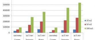
- Economical. Energy savings, compared to using heating radiators, can reach 50%.
- Long service period. In the collector device, the only element that can wear out is the pipe. The service life of such an element is 50 years.
The principle of operation of the collector
A water floor system usually contains several circuits for distributing coolant through pipes. Each of them has a separate input and output connected to the collector. It consists of two combs: from one, hot water is supplied to the pipes of the system, and in the other, its return flows, which have given up part of the heat, are combined together and returned for heating.
Preparing the coolant involves mixing hot and cold water to obtain the required temperature. Warm floors do not require a lot of heating of the coolant. If the temperature in radiators is 70-95°C, then for heated floors it does not exceed 30-55°C. It is impossible to walk barefoot on hot ceramic tiles, and other coatings warp due to high temperatures.
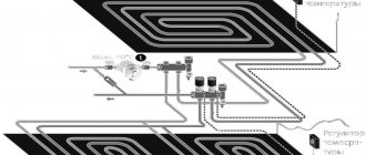
The manifold uses a mixing unit, which is a pump with pipelines that ensures mixing of the forward flow with the return flow and obtaining one with a certain temperature. The best method is sequential mixing (Fig. below), where the highest productivity is achieved.
Sequential connection diagram of pipes with coolant
Red arrows indicate the flow of hot coolant, blue arrows indicate coolant flow. The temperature of the mixture in front of the upper comb is controlled by a thermostatic valve.
The mixer is also used in systems where underfloor heating is combined with radiator heating. The ratio of portions of hot and cooled coolant is maintained by valves while temperature is controlled by heat, pressure and weather sensors. Natural circulation is no longer used in many places, and pumps are connected to the collectors to maintain pressure in the system.
In simple systems, the coolant is not mixed. It is supplied by a circulation pump installed in the return pipeline.
How to choose a manifold for a heated floor?
Collector stabilization scheme.
Such a design should be selected based on how much money can be spent on its construction. In addition, there is a parameter that must be observed. A similar parameter is the number of outputs on the collector. This number will depend on how many pipes need to be connected to the collector structure.
It is not possible to correctly calculate the number of loops correctly in all cases. They differ from each other in terms of room area. In some rooms it may be necessary to install two loops. An approximate calculation of the number of such elements can be made based on the fact that there are 6.5 m/p of pipes per 1 m². The resulting value must be multiplied by the area of the heated room. The final number should be compared with the existing lengths of pipes in the coil. It should be noted that in some cases it is best to make several loops so that there is not a lot of extra pipe left from the bay. You can take a collector with one more circuit, and plug the extra one.
Assembly
It is not difficult to assemble a set of purchased manifolds, the sequence is as follows:
- Twist the supply and return pipes together.
- Secure the connecting tubes to the stationary brackets.
- Install plugs, fasteners, shut-off valves and control devices.
There will be no difficulties in assembling, since each kit has assembly instructions with illustrations.
Next, fastening to the wall is carried out; you need to choose a place in accordance with the recommendations presented. It is important to first fix the collector to the wall and only then connect the circulation pump and valve. It is not worth doing this in a different order, since it is inconvenient to secure the entire assembly.
As for the installation of the pump and thermal head, it is carried out in accordance with the selected scheme. The next stage is the supply of the main pipe and pipes from the heated floor circuits.
Why do you need to install valves in the manifold?
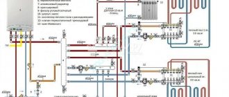
Installation diagram of the collector and sensors.
A two-way valve will allow the coolant to flow in one direction, but it has a small capacity. The advantage of using a two-way valve is that in this case the coolant will flow smoothly and without fluctuations. Such devices have low throughput, and therefore are used in small rooms. The latest valve models can be equipped with a servo drive. Such an element is an engine with a valve placement sensor. Using a servo drive, you can open and close the fluid passage hole with precision.
A three-way valve will mix or separate coolant flows. In the body of the structure there are several pipes through which the element is connected to the heating pipes. The valve will receive fluid from the boiler, transfer it to the heating system, and also receive fluid from the return pipe in order to mix the latter with the hot supply. It is recommended to install a three-way valve in autonomous heating systems at the outlet of the collector system, where it is not necessary to limit the flow rate during uniform mixing.
Article on the topic: Design of a veranda for a dacha: photos and projects of summer terraces
With prolonged use, the valve may become clogged. To make it easy to replace such an element, a detachable coupling for connecting all elements should be used in the connection.
If the thermal fluid distribution scheme involves the installation of several collectors, then at the output of each element you will need to install a splitter with a structure for air exhaust.
Types of absorbers in vacuum tubular collectors.
Air is exhausted from the top of the splitter. The drain valve should be installed at the bottom of the structure. It will be used to drain the coolant during the repair of the heating system.
Some heating system designs do not require mixing of liquids; in such cases, valves may not be installed. To maintain a constant temperature in such systems, you will need to install a circulation pump. Such a design must be installed directly in the return pipe so that unnecessary intake of coolant from the heating system can be eliminated.
Purpose of the collector
The distributor in the heating system is a very important component, as necessary as a pump or boiler. This device serves as a distribution area and ensures the supply of heated water to all appliances connected to the system. To ensure uninterrupted operation of each individual branch of the circuit, the collector is additionally equipped with various air filters and thermometers, temperature control and shut-off sensors, and thermal control devices.
The collector is an element that, according to technical parameters, mixes and distributes warm water from parallel circuits of the heating system. Due to its large cross-section and low speed, the specified parameters are equalized.
Tips for installing a manifold for heated floors
Types of collectors.
You can install a similar structure for a heated floor yourself. The distribution manifold is in most cases located in a manifold cabinet or a separate room, which is hidden in the wall. When installing the structure, you should consider the following nuances:
- You should try to place the distribution manifold at the highest point of the heating system in relation to the level of the placed loops. This is necessary so that, if necessary, air can be removed from the installed pipes.
- The distribution manifold should be located in the central part of the premises that are heated.
- You will need to connect circuits of the same length to one structure. If no such contours are available, the length should be as close as possible to the length of the element that is placed nearby.
Components
Typically, the collector pipe has connecting nodes - according to the number of thermal circuits.
In total, the collector contains two pipes:
- one performs the functions of a mixer and supply of coolant to the circuits;
- the other serves to collect return flow from all circuits and return the water cooled in the circuits to the boiler, and, partially, through a two- or three-way valve, to the output mixer.
Hot water from the boiler is added to the mixer by turning on a thermostatic valve, which is placed in the path of water supply to the mixer. When the temperature in the mixer drops below the permissible level (we remember - this is 40°C), the valve supplies a portion of hot water.
This group of bimetallic valves changes the flow area, as well as the volume of water passed through. This allows you to set the temperature as desired. Flow sensors are installed at the return inlets, and the return comb is also equipped with an air vent. The coolant is pumped through the system using a water pump, which creates the necessary pressure in the line.
A complete set of manifold parts also contains various plumbing fittings. In a set of devices for warm water floors, the collector is perhaps the most important of them, as it provides:
- safety and proper use of floors;
- the ability to configure comfortable conditions for using heating appliances.
Additional devices that are installed in manifolds
Diagram of the solar collector.
To automatically adjust the floor heating device, weather sensors can be installed in the collector structure. If it gets sharply cold outside, the heating intensity will increase. The weather sensor will send signals to turn the boiler on and off. It is worth noting that manual adjustment is ineffective. Sensors that depend on the weather will check the temperature several times per minute. If necessary, the servos will rotate the valve in either direction by 5°.
Related article: What is the difference between pyrometers?
In order to assemble a simple collector, you need to prepare the following elements:
- mixing valve;
- nipple;
- adapter;
- tee;
- knee;
- coupling;
- circulation pump;
- ball valve;
- manifold connector;
- collector;
- external and internal connectors;
- device for air removal.
Vacuum manifold diagram.
It is also not very difficult to assemble a multi-circuit manifold for a heated floor with your own hands. It includes the following elements:
- thermal head with sensor;
- mixing valve;
- coupling;
- screw;
- tee;
- nipple;
- circulation pump with connected taps;
- stub;
- collector device;
- Ball Valves;
- fitting;
- union nuts;
- metal-plastic pipes.
If you plan to connect pipes of the “warm floor” system to the collector structure, then crimp fittings should be used to fix them. Before fixing to the pipe, you need to make a shallow chamfer so that the pipe can fit snugly into the seat for seating. After installing and connecting the collector structure to the boiler and to the heating system, you will need to pressurize the pipes and check their functionality. Pressure testing should be carried out for approximately 3-5 hours. In this case, even with a small heat, she will be able to express herself. The system will be warmed up at maximum level for several hours. The entire collector structure must be placed in a special cabinet, which is installed on the wall near the heating boiler or near the connection point to the heated floor.
Standard designs of this type are in most cases designed for 2-12 circuits. Today in construction supermarkets you can find devices of varying levels of complexity. The simplest device is in the form of a pipe, the standard hole diameter is 1 inch, and the diameter of the outlet channel is 0.5 inches. In this case, similar elements are equipped with shutters. For such a design, you need to purchase pumping equipment, an air release valve and a control system. It is not necessary to install servos and thermometers. In the process of purchasing or making a structure for a heated floor with your own hands, you should be guided by your own financial capabilities. You also need to consider what type of structure will be needed.
Almost anyone can assemble a collector structure. To do this, you should use one of the existing schemes.
Types of collectors
Piping of underfloor heating pipes in the manifold is carried out according to the following schemes:
- Parallel - with this scheme, a loss of temperature occurs, which will affect the heating efficiency. The use of the circuit is due to the ability to install a two-way valve, and with it, adjusting the system is convenient.
- Sequential - this scheme is effective and has high performance compared to the previous one. The amount of thermal energy emitted by a floor-mounted heater is maximum.
- A combined scheme is the best solution, because you can quickly connect the collector, but also carry out the work yourself without involving specialists.