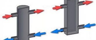
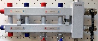
A hydraulic arrow is an additional device for the heating system, which balances and protects it. The operating principle is to separate hydraulic flows, which is why it is also called a “hydraulic separator”.
Correct use of a hydraulic needle allows you to coordinate the operation of all elements of the heating system, increase the efficiency of the pump with the boiler, which helps improve energy efficiency and significantly reduces consumable resources (electricity, fuel). The main purpose of the device is to ensure economical and efficient operation of the boiler.
Design and principle of operation
The hydraulic arrow is a container with several pipes, as well as internal elements. The number of pipes can be from 4 or more (depending on the number of heating system circuits). Their location is determined by calculations for a specific system.
Depending on the size of the system, the connection of pipes to the circuit is:
- threaded - used for small systems;
- flanged - for large ones.
The dimensions of the device directly depend on the volume of the circuit and its power. Installation is carried out on support posts for metal cases, and using brackets for small sizes.
The material used is copper, polypropylene or stainless steel. The housing must be treated with an anti-corrosion agent.
Important! Polymer products can be used in systems with a boiler with a power of 14 to 35 kW. It is extremely difficult to install such a device yourself.
In addition to standard functions, the device can be manufactured with a number of additional ones, namely:
- Deaeration – helps eliminate gases in water that arise due to its heating. To perform this function, a separating plate is installed inside the device, and its walls attract gas particles. The release of accumulated air can be automatic or require manual intervention.
- Magnetic treatment of liquid – accumulates metal particles and scale. To do this, magnetic rods equipped with special magnets consisting of boron, iron, and neodymium alloys are mounted inside the housing.
- Filtration – removes and removes debris (sludge, deposits, foreign particles) from return water. This process is carried out using barrier plates that are installed at the bottom of the housing.
They help improve performance and reduce the cost of purchasing unnecessary devices, such as mud collectors, air collectors or sludge drains.
Hydraulic arrow for heating systems, diagram and how it works
A hydraulic separator is a hollow vertical vessel that consists of large-diameter pipes (square profile) with elliptical-type plugs at the ends. The dimensions of the separator are determined by the power of the boiler and depend on the number and volume of the circuit.
The hydraulic needle has a massive metal housing. It is installed on supports so that there is no line voltage on the pipeline. Compact devices are attached to the wall using a bracket. The heating pipeline and the hydraulic arrow pipe are connected using flanges or threads.
Additional parameters of heating system equipment
Modern models, as a rule, are combined with the functions of a separator, temperature regulator and separator. The thermostat valve provides a temperature gradient on the secondary circuit. The release of dissolved oxygen from the coolant reduces the risk of erosion of the internal surfaces of equipment. Removing suspended particles from the flow will help extend the life of the wheel and bearings of circulation pumps.
Perforated horizontal partitions divide the internal volume in half. The return flows are connected in the zero point zone and slide in different directions without creating additional resistance.
Equipment and characteristic differences of hydraulic guns
The separator kit depends on the internal content and the number of circuits for which it is designed. A mandatory element is an automatic air vent 1/2, equipped with a check valve or ball valve. For custom installations, removable thermal insulation is included.
Hydraulic guns of the GS type have built-in elements to eliminate air and sludge. The MGS (multifunctional hydraulic guns) kit contains magnetic rods and the ability to adjust the support height within 10 cm. Devices such as GS, MGS, flexbalance and maibes can be used for dual-circuit systems, but they can be equipped with a manifold.
Principle of operation
There are three possible options:
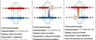
- The coolant flow per unit time through the boiler (Q1) is equal to its flow through the heating system (Q2). Productivity in this case: Q1=Q2. The temperature of the water leaving the boiler and entering the circuit is the same. There is no vertical flow direction in the hydraulic arrow, but in practice this happens extremely rarely. The design has a sufficient level of total power.
- The boiler performance is much higher than that required for the heating system: Q1>Q2. In this case, a vertical flow of water from top to bottom is formed inside the hydraulic arrow, part of it passes into the return line. The temperature of the liquid at the inlet to the boiler increases, and the automatic system begins to reduce the fuel supply, which puts the system into an economical operating mode. A similar scheme is typical for the summer period, when heating is not required, and the boiler operates exclusively in hot water supply (DHW) mode.
- The boiler's performance is not enough for the heating system: Q1 In this scheme, a vertical flow appears in the hydraulic arrow, directed from bottom to top, in which part of the return flow is directed into the supply flow. The temperature of the water entering the circuit decreases and its volume increases. It is rational to use this option for systems with a large number of consumers, for example, for radiator heating, underfloor heating, hot water supply and others.
Operating modes
To understand why a hydraulic arrow is needed in a heating system from a technical point of view, it is necessary to consider the main options for its application in practice. The following three schemes are distinguished:
- Equilibrium operation of the system. The hydroseparator operates in neutral mode without affecting the system. In this case, the pumping equipment of the heating unit pumps the same amount of coolant as is required for the heating system. At the same time, the indicators of heating, pressure, flow and generated heat correspond to theoretical calculations - both on the supply and return lines. However, in reality such conditions never arise, since after a short time all the characteristics of the system undergo changes.
3 operating modes of the hydraulic gun Source stroychik.ru
- The heating circuit consumes more coolant than the heat exchanger. This is the most common situation that arises in practice when the hydraulic separator works for its intended purpose. Vertical redistribution flows arise in it - from the return the coolant is mixed into the supply. There is a threat of heat stroke, since the lack of a thermal agent activates sensors, which in turn send a command to increase the operation of the heat generator. In this case, the consumer will still not receive the required amount of heat.
Scheme of work
Hydroseparation works according to the following scheme:
- The flow of water from the boiler enters the hydraulic arrow , where it changes its direction and reduces its speed.
- As a result of the changes, air is released, which gradually accumulates at the top of the housing. The air is periodically vented.
- Then the flow is directed according to one of the above schemes, along the consumer circuit.
- The cooled water returns to the hydraulic switch and passes through the dividing partitions, where it is cleaned of sludge.
- Sludge accumulates at the bottom of the housing and is periodically discharged.
- Purified water flows back into the boiler.
Piping two boilers operating in cascade
Benefits of use
Using the device in a heating system has a number of advantages:
- A hydraulic gun is required to obtain a guarantee that technical specifications are met.
- With its help, the temperature regime and hydraulic balance in the system are maintained.
- The circulation in all circuits is equalized.
- The boiler is protected from thermal shock.
- Reduces fuel and electricity costs.
- Reduces the level of hydraulic resistance.
- It is possible to connect additional components (expansion tank, air vent, etc.).
Video description
Video about the hydraulic separator and its purpose:
The calculation is carried out in the following several ways:
- Maximum coolant flow rate.
Calculated by the formula:
D = 3*d*√Mp/Vd
D is the diameter of the hydraulic needle, d is the diameter of the nozzle, MP is the maximum flow for the boiler, Vd is the maximum speed (0.2 m/s).
For example:
7*3*√8/02 = 21*√40 = 21*6.32 = 132.8 cm – 133 cm – diameter of the hydraulic needle.
The diameter of the pipe is 7 cm, the boiler flow rate is 8 cubic meters per hour.
- Highest boiler power.
The calculation is carried out using a similar formula:
D = 3*d*√Mk/(Vd * Traz)
However, some replacement parameters appear in it:
Mk – maximum boiler power, for example 60 kW,
Traz – the difference in heating of the coolant in the supply and return flows, for example 15 degrees.
For example:
21*√60/(02 * 15) = 21*4.4 = 94 cm.
- The length of the body of the hydraulic needle itself. The length of the device depends on the diameter and location of the pipes. Below is a diagram for calculating the characteristics. In the first version it will be equal to 12 diameters, in the second - 13.
Scheme for calculating the length of the hydraulic arrow according to the location of the pipes Source stroychik.ru
Advice! When calculating the parameters of a hydraulic arrow, it is important to determine the maximum possible coolant speed. If the flow moves quickly enough, a characteristic noise will arise in the system, significantly reducing the comfort in the house. Therefore, in order to avoid this negative effect, this parameter is limited to a value not exceeding 0.2 m/s.
Types of separators
Classification of separators:
- Depending on volume:
- large – 200-300 l.;
- medium - from 20 to 150 liters;
- small - less than 20 liters.
- Depending on the number of circuits:
- double-circuit;
- multi-circuit.
- Depending on the section shape:
- round;
- square.
- Depending on location:
- horizontal;
- at an angle;
- vertical.
- Depending on the position of the pipes:
- parallel (on the same axis);
- alternating (on different axes).
Briefly about the main thing
A hydraulic separator for heating is a metal closed container with pipes mounted in front of the boiler. Designed for optimal distribution of coolant between consumers, as well as regulation of the heating level between forward and reverse flows in heating systems with forced circulation and at least 2 pumps. The need to install the device arises when the following consumers are simultaneously present:
- Separate radiator lines.
- Water heated floor system.
- Boiler operating on a heating boiler.
- Warm water ventilation.
The device is also needed to smooth out the effects of temperature changes on the cast iron heat exchanger. In this case, the hydraulic arrow can operate in three modes - in equilibrium, with insufficient power of the heating circuit and its superiority over the consumer. The last option is the most optimal. Before installation, the device must be calculated in terms of throughput, diameter and length, depending on the diameter and location of the connected pipes.
Ratings 0
Selection of hydraulic arrows
The main point when choosing a hydraulic arrow is the diameter, since the height does not play a special role. The larger the volume of the device, the better and better the temperature equalization occurs, which is especially in demand for boilers with solid fuel (coal, pallets, firewood).
When choosing a suitable model, you need to consider how many circuits will be connected to it. To find out the best option, you should determine the power of the circuit, as well as the volume of coolant. For this purpose, a hydraulic engineering calculation is carried out.
Calculation
Calculations should be carried out based on the maximum value of water flow and the level of its speed in the hydraulic separator and tubes.
You can make the calculation using two methods:
Using the maximum water flow value.
D=3*d=1000*√((4*G)/(π*3600*ω))=18.8*√(G/ω),(mm)
Where:
D – hydraulic needle diameter, mm;
d – tube diameter, mm;
G – maximum value of water flow through the arrow, cubic meters. m./hour;
ω – maximum value of the flow velocity in the hydraulic arrows (taken as 0.2 m/sec.).
Using the maximum value of the boiler power, the difference between the flow temperatures becomes 10°C.
D=3*d=1000*√((4*P)/(π*c*ω*∆T))=17.4*√(P/(ω*∆T)), (mm)
Where:
D – hydraulic needle diameter, mm;
d – tube diameter, mm;
с – heat capacity of the coolant;
P – maximum power value of boiler equipment, kW;
∆T – Difference between supply and return temperatures, °C.
After making the calculations, you will find out what diameter of the device is required for the heating system. The resulting value is the minimum value that can be used. If the diameter is higher than this, the system will continue to function normally, if lower, a disaster is possible.
Connection diagram for hydraulic heating arrow
How to select parameters
The hydraulic separator is selected taking into account the maximum possible coolant flow rate. The fact is that at high speeds of liquid movement through the pipes, it begins to make noise. To avoid this effect, the maximum speed is assumed to be 0.2 m/s.
Parameters required for the hydraulic separator
By maximum coolant flow
How to calculate the diameter of a hydraulic arrow using this method, you need to know the maximum coolant flow that is possible in the circuit and the diameter of the pipes. You know the diameter of the pipes, which pipe you will use for wiring. We know the maximum flow (it is in the technical specifications), and the flow rate through the circuits depends on their volume and is determined when selecting circuit pumps. The flow rate for all circuits is added and compared with the power of the boiler pump. A large value is substituted into the formula to calculate the volume of the hydraulic needle.
Formula for calculating the diameter of a hydraulic separator for a heating system depending on the maximum coolant flow
Let's give an example. Let the maximum flow rate in the system be 7.6 cubic meters/hour. The permissible maximum speed is taken as standard - 0.2 m/s, the diameter of the pipes is 6.3 cm (2.5 inch pipes). In this case we get: 18.9 * √ 7.6/0.2 = 18.9 * √38 = 18.9 * 6.16 = 116.424 mm. If we round, we find that the diameter of the hydraulic needle should be 116 mm.
According to the maximum boiler power
The second method is to select a hydraulic needle according to the boiler power. The estimate will be approximate, but it can be trusted. The boiler power and the difference in coolant temperatures in the supply and return pipelines will be needed.
Calculation of hydraulic arrow according to boiler power
The calculation is also simple. Let the maximum boiler power be 50 kW, the temperature delta be 10°C, the diameters of the pipes be the same - 6.3 cm. Substituting the numbers, we get - 18.9 * √ 50 / 0.2 * 10 = 18.9 * √ 25 = 18.9*5 = 94.5 mm. Rounding, we get the diameter of the hydraulic needle 95 mm.
How to find the length of the hydraulic arrow
We have decided on the diameter of the hydraulic separator for heating, but we also need to know the length. It is selected depending on the diameter of the connected pipes. There are two types of hydraulic arrows for heating - with taps located one opposite the other and with alternating pipes (located offset from one another).
Determining the length of the hydraulic arrow from a round pipe
It is easy to calculate the length in this case - in the first case it is 12d, in the second - 13d. For medium-sized systems, you can select the diameter depending on the pipes - 3*d. As you can see, nothing complicated. You can calculate it yourself.
Connecting the device
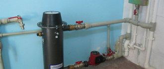
The hydraulic arrow must be installed close to the boiler. A pipe with a supply from the boiler is connected to the upper nozzles, on which circulation pumps are additionally mounted (one before the hydraulic arrow, the other after), and a flow of cold water (return) is connected to the lower nozzles.
The device should be mounted vertically so that there is room for the accumulation and removal of air and sludge.
Important! The use of circulation pumps allows you to speed up the flow and reduce the level of condensate settling on the metal parts of the boiler.
For boiler equipment with solid fuel, a three-way thermostatic valve is used, which is mounted at the ends of the outlet pipes.
After installation, it is necessary to connect the hydraulic separator. To do this, you will need to fill everything with liquid and turn on the boiler. At first, the water will circulate in a small circle (up to the hydraulic arrow), since the pumps are not connected at insufficient temperature. Then, after warming up the liquid and turning on the secondary circuit pumps, it will begin to circulate in a large circle.
Do-it-yourself hydraulic arrow
The hydraulic distributor can be made independently from pipes of a suitable diameter, a metal tank, etc. You only need to weld the pipes, as well as the upper and lower bottom.
Important! Welding must be done at a high level to prevent debris from getting inside. Therefore, contact a professional welder.
Step by step guide:
- Calculate the diameter of the pipes using the above formulas.
- Draw up a schematic drawing of the device. Please note that the container should be divided into several spaces:
- The distance from the bottom to the first lower pipe should be about 10-15 cm so that sludge collects in it;
- The distance from the top to the first tube on top should also be about 10 cm, for air accumulation.
- The inlet and outlet of the upper pipes are regulated by the temperature gradient. The upper tubes can be parallel to each other or alternate. Important! If the pipes are on the same axis, then due to the direct flow, the air removal is very weak, which is why air jams occur.
- The higher the upper outlet pipe is located, the higher the temperature of the incoming flow. Important! If the upper outlet pipe is located lower than the inlet pipe, then water will flow into it only after it has completely warmed up.
- The inlet tube at the top should not be at the highest point, since the hot flow will not move in the device and the water will not be able to mix.
- Carry out welding work.
- Check the device for leaks by closing the holes and filling it with water. Then leave it in this state for a day. If there are no leaks, the device can be installed.
If the upper outlet pipe is located lower than the inlet pipe, then water will flow into it only after it has completely warmed up
Price
The price of products depends on several factors:
- power;
- volume;
- material;
- the number of circuits that need to be connected;
- manufacturer's company;
- promotion of the brand.
Approximate cost of domestically produced hydraulic arrows:
- NORTH-60 , power up to 50 kW – 2560 rubles;
- SEVER-220 , power up to 500 kW – 25,500 rubles;
- Gidruss GR-150-40 , power up to 150 kW – 8300 rubles.
- Warme WGR80 with outlets for an air valve and a mud pan, with a power of up to 80 kW - from 3,700 rubles, with a power of up to 122 kW - from 6,000 rubles.
Approximate cost of foreign-made hydraulic arrows:
- Meibes MHK 32 with power up to 70 kW – 13,800 rubles (manufacturer Germany).
- Bosch HW 50 with power up to 105 kW – 12,000 rubles (manufacturer Germany).
Blitz tips
- Installation of the device is a prerequisite for obtaining a warranty from the manufacturer for all components of the heating system.
- For complex systems with multiple circuits , elements such as a temperature sensor, a pressure gauge and a system starting line are required.
- The device is simply indispensable for cast iron boilers , as it protects them from sudden thermal shocks.
- For boilers with solid fuel, it is advisable to use a hydraulic separator with a volume of 100-300 liters.
The hydraulic arrow is an integral element in complex heating systems.
Connection features
Knowing what a hydraulic valve is in a heating system allows you to correctly select it according to its parameters and correctly connect it. Installation of the device is carried out according to the general rules of plumbing installation. The device must first of all be correctly selected according to the main parameters - throughput, number of pipes, dimensions.
It is also necessary to remember what a hydraulic arrow is - the operating principle of this device is based on forced circulation. The system must have at least two pumps. One of them ensures the operation of the heat exchange circuit of the boiler, the other – the consumer system. If this condition is not met, the device will not only be useless, but even harmful and will act as an obstacle to the movement of the coolant.
