The feasibility of installing a collector system
But it is impossible to install a collector heating system in an apartment of old multi-storey buildings, because a tee heating system is already working there.
For the collector system to operate, it is necessary to close the hydraulic circuit, which is necessary to create coolant circulation in the system. If a closed hydraulic circuit is created in one apartment, then other apartments will be cut off from the heating system. The collector heating system also cannot be used in areas with unstable power supply, since when the circulation pump stops, the water will freeze and the pipes will fail. But the situation can be somewhat improved by using
Collector heating system. Principles of its work.
How to install a mixing unit for a heated floor with your own hands
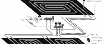
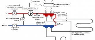
As I said earlier, this type of heating system is most often used in two or more storey buildings. But no one will forbid you to use it in a one-story house. It all depends on expediency. In addition to heating devices, an indirect heating boiler or a heating system for a swimming pool or greenhouse can be connected to the collector. So in a one-story house you can use this kind of trick. The main thing is not to forget that in a collector heating system there can only be forced circulation of the coolant. This means that it must have at least one, and most often several, circulation pumps. Look at the picture below:
The figure shows a diagram without an indirect heating boiler. This is done here because a double-circuit gas boiler is used. Well, if the boiler is single-circuit, then everything will look a little different:
It has everything modern homeowners love:
- Radiators.
- Water heated floors.
- Backup electric boiler.
- Indirect heating boiler.
If you don’t count them together with the boiler pump, then there will be 5 of them. To ensure that the circulation pumps do not create a pressure difference between the “supply” manifold and the “return” manifold, a hydraulic arrow is used here. Thanks to it, the boiler circulation pump can always provide the required coolant flow through the boiler heat exchanger, which has a positive effect on its service life. The underfloor heating circuits are connected through their collectors with autonomous circulation groups. Here you need to take into account the possibility of an emergency power outage. To ensure the operation of the “brain” of the boiler and circulation pumps during a shutdown, you will need. Without it, the circulation of coolant in the system will stop, and this is fraught with all sorts of unpleasant consequences.
The main advantage of this heating scheme is the ability to turn off individual branches without stopping the entire system. This feature is very helpful in case of emergency repairs. Well, the downside will probably be the price of all this pleasure. Although, if you are doing it for yourself and for a long time, then it makes sense to do everything wisely. Otherwise, your stinginess will make you pay twice! On this optimistic note, I will end this post, I look forward to your questions and likes on social networks!
Functionality and principle of operation of the flow meter
The main function of flow meters or, as they are also called, float rotameters in a heated floor system is to regulate the coolant flow in water circuits. Installing such a device allows you to:
- avoid excessive consumption of electrical energy in the process of heating the coolant;
- ensure uniform heating of all water circuits;
- eliminate temperature fluctuations in different rooms.
The need to use flow meters arises in buildings where floor coverings of different areas are heated. Large rooms require a longer pipeline length, so they heat up less intensely than small rooms. Therefore, it is possible to achieve uniform heating and ensure a comfortable temperature throughout the entire house only with such a device.
The flow meter for a floor heating system is a mechanical type device with a plastic or brass housing. Inside it is a float made of polypropylene. On the top of the body there is a transparent bulb with markings. During the circulation of the coolant, the float comes into action, moving up and down. According to its location, you can use a scale to determine the volume of liquid in the pipeline.
Electromagnetic flow meters
Connecting a heated floor to a thermostat
Their operating principle is based on the law of electromagnetic induction, according to which an emf is induced in an electrically conductive liquid passing through an electromagnetic field, proportional to the speed of the flow (conductor).
Such flow meters have found application in volumetric metering systems for coolant and water at industrial and energy enterprises. Disadvantage: high cost and weight for diameters greater than 300-400 mm, difficulty in removing for verification.
Rod electromagnetic water meters operate on the principle of immersing a sensor in a liquid, where the flow rate is measured. Such meters determine the flow of cold water in completely filled pipelines.
Selection, installation and adjustment of flow meters
Which electric boiler for heated floors is better to choose?
A water heated floor, as a rule, consists of several circuits of plastic pipes. Hot water, moving through them, gives off its heat and returns through the return supply part of the system. The collector (comb system) of a warm water floor is designed to collect cooled water, mix and supply heated water. In other words, this is a unit that controls the operation of the floor heating system.
To regulate the temperature, flow meters are provided in the manifold. These devices control the flow of coolant, in this case water.
Why do you need a flow meter?
Theoretically, it is quite possible to do without installing a flow meter in the manifold. However, if you do not install this device, then:
- Different rooms will have different temperatures;
- There may be excessive consumption of electricity to heat water in the system;
- Different circuits will heat up unevenly.
A simple example can be given: a bathroom and a bedroom. A gas or electric boiler heats water equally for both the bath and the bedroom. But the bathroom is at least 3 times smaller in area than the bedroom.
Accordingly, the bathroom will be hot and the bedroom will be cool with the same water supply to the floor heating system. This situation is due to the fact that in the bedroom the total length of plastic pipes in the area is much greater.
It is precisely in order to regulate a comfortable temperature in the entire apartment that it is desirable to install such a device.
Advice! When installing a water heated floor, you should strive to make the contours of the pipes approximately the same length. This will save energy costs and allow you to more accurately regulate the temperature.
Principle of operation
The device is installed on the return collector outlets. When the set temperature in the system is reached, the manifold valves narrow the lumen of the energy supply or close it completely. This principle of operation is possible with full automation of the system. For this purpose, the collector is equipped with a temperature sensor.
The flow meter itself consists of several parts:
- Frame;
- Transparent flask with scale;
- Float.
The flask is usually made of durable glass; the body can be plastic or brass. The float is located inside the flask; it serves as an indicator of the coolant speed. The flow meter is also called a float rotameter.
In an automatic water heated floor collector, balancing of coolant flow is carried out using a temperature sensor. If the latter is not provided, then the rotameter can be adjusted manually.
Step-by-step instructions for installation and adjustment
H2_2
The rotameter is installed strictly vertically. To ensure that the liquid level in the flask is accurate, the collector itself is also mounted according to the level. If the comb pipe is installed crookedly, the temperature adjustment will be incorrect.
Since finishing work often occurs after installation of the collector, it is necessary to protect the assembly and its components from possible damage. The best option is to make a niche or a special cabinet for it in the wall.
Installation and adjustment:
- Using a wrench, screw the flow meter into the process inlet of the return line of the manifold;
- Turn the membrane (flask) counterclockwise to open the pressure meter;
- Remove the factory protective ring;
- Turn the brass housing ring clockwise to the desired pressure level. This is balancing the energy flow rate. The float on the scale will indicate the set value;
- Cover the brass ring with a cover plate. This must be done to avoid damage to the device, especially if the water heated floor unit is not closed in a niche or cabinet;
- Check the system operation.
During operation of the unit, the flask remains open so that the level of the water float is visible. If balancing is needed during operation, the membrane is simply turned in the desired direction.
Choosing a flow meter for water heated floors
High-quality rotameters should be accompanied by a guarantee of 5-7 years of stable operation. It is recommended to choose flow meters with a brass body
You should also pay attention to the flask; it should be made of transparent glass with good visibility of the water level scale. However, there is an opinion that it is better to choose products with a membrane made of impact-resistant plastic
When choosing a device, you need to take into account the area of the pipeline system
It is also important whether the node is automated or not. In the first case, balancing will be necessary extremely rarely; mechanized collectors require closer attention
Source:
The essence of the collector
The main feature of a water heated floor is the coolant; the water gradually moves to the heating circuit and gives off part of its energy.
That is why the heating of the floor occurs with the release of heat to the air that is mixed inside the room, and it, as is known, is directed from the bottom up. A number of devices are responsible for supplying warm water to the circuit and intensity:
- the valve is considered the main one;
- a pump must be present;
- collector.
All control of water distribution is carried out using a flow meter. It is this device that plays the main role in the operation of the entire system.
All collectors are designed specifically for hot water, and they are also necessary to collect waste material. In the unit itself, the process of mixing hot water that comes from the source and return takes place.
Thanks to rotameters, there is a chance to ensure that the entire volume of water reaches the floors. Simply put, the equipment will independently control the heat in the water field.
Floor heating cannot do without a rotameter. The design includes a body made of plastic, but there are models made of brass. A float is placed inside any device. There is a flask with a scale.
We recommend: Features of the “combined heating: warm floor and radiators” system
The float can move up and down and at the same time points to a certain division of the scale. Judging by it, it will be possible to judge the volume of coolant that circulates in the pipeline.
If we talk about theory, the system works without a device, but in this case the adjustment has to be done manually, relying on your own sensations.
The flow meter for the underfloor heating manifold plays an important role; if it is abandoned, the following problems will arise:
- the fact is that in the absence of a flow meter, some floor contours can be supplied with coolants, while the features of the room will not be taken into account;
- the energy consumption used to operate heating devices, for example, either gas or electricity, will be excessively increased.
Let's say you plan to simultaneously heat the bathroom and another room, for example, a bedroom. A gas-powered boiler will heat water for the bathroom and bedroom absolutely identically, that is, there will be one temperature regime.
It is important to install the equipment correctly; to do this, you need to screw the device itself into the collector socket. Fixation occurs due to the nut. When improving a heated floor, it is advisable to try to control the length of the heat pipeline of all circuits, without paying any attention to the configuration. This will simplify the adjustment of the system and it will still be possible to achieve normal temperature parameters.
But we must take into account that the bathroom is small in size, in order to heat it you need less water from the boiler, but more water is required to supply the bedroom. It is possible to compare the heat of each room, but only in this case will you need to use a flow meter.
If you use this device, the temperature will be set in the bathroom and bedroom for a comfortable stay there.
Having carefully assessed the principle of operation of this device, we can draw the following conclusions:
- the device can function completely autonomously, without the need to use any additional power sources;
- the main operating principle of the flow meter makes it possible to sufficiently consume the coolant for the circuit and further significantly reduce the energy costs of all heating devices;
- the design of the entire device is capable of providing control over the amount of water entering the pipes;
- the manifold, which is installed together with the flow meter, makes it much easier to control the operation of the entire system in general. Also, installation of the system is not complicated and does not require special maintenance.
We recommend: How to install damper tape for underfloor heating?
Manual adjustment of coolant temperature
How you adjust the temperature will depend entirely on the equipment you are using. For example, if a system with a temperature controller and a servo drive is installed, then the setup is carried out according to the instructions from the manufacturer of this device. In this case, the adjustment is performed automatically. Now let's look at the manual method of setting the temperature using thermal heads.
Thermal heads can be installed both on the supply and return side of the coolant.
First of all, the system up to the heated floor must be completely filled with coolant and freed from air.
But it is important not to rush here, otherwise air jams may form. If the connection was made from the boiler, then before starting water into the heating circuits, turn off all taps
Afterwards, open the supply/return loop on one loop, filling it with coolant. The air should come out of it through the air vent. Now turn on the circulation pump so that the coolant begins to move in this loop. At the same time, turn the temperature on the boiler to 35°. To the touch you should feel that hot water is flowing in the return and supply in the heating circuit. If everything works properly, close this loop and open a new one. Using this method, you pump and check each loop of the heating circuit. When you have configured each circuit, you open all the taps and adjust the required temperature by touch. In some loops the faucet will need to be opened completely, while in others it is enough to open it slightly.
The coolant temperature in each circuit may be different. There are several reasons for this, such as the length of the loop. The shorter the circuit, the faster it warms up and vice versa.
Thus, manual temperature adjustment is carried out. It is enough to do it once a year. But here it is important to take into account the nuance. The underfloor heating system is inertial. What does this mean in practice? If you make changes to one of the hinges, you will have to wait several hours to notice a noticeable change in the temperature inside the room.
If you installed flow meters on the collector, the difference between the readings can reach up to 0.5 liters.
Results
It is important to ensure that when the water floor heating system is operating, the flow rate on the collector is visible. This is necessary for maintenance. Each water circuit must have its own flow meter.
We recommend: How to install a heated film floor?
As you can see, in the equipment, each element performs its own functions, so each one needs to be given sufficient attention, and in order for the entire system to work as one whole, it is worth equipping it with a flow meter and a collector, which will evenly distribute all the heat.
- Related Posts
- Is it possible to lay laminate flooring on a heated floor?
- What concrete is suitable for a warm water floor?
- How to connect a mixing valve for a heated floor?
- Which rod infrared heated floor should I choose?
- Do you need a mixer for underfloor heating?
- How are pipes for underfloor heating made of cross-linked polyethylene laid?
VALTEC combined heating diagram
We present to your attention an example of a modern energy-efficient heating system based on VALTEC equipment. It is designed for a country house or any other facility with an autonomous heat source (boiler, etc.). The scheme provides for the combined use of traditional radiators and underfloor heating. This combination of technologies, as well as the applied automation, makes it possible to provide a high level of comfort at optimal costs for the purchase of equipment and its operation. The diagram uses and displays components from the current VALTEC range.
| № | vendor code | Name | Manufacturer |
| 1 | VT.COMBI.S | Pumping and mixing unit | VALTEC |
| 2 | VTC.596EMNX | Manifold block with flow meters | VALTEC |
| 3 | VTC.586EMNX | Stainless steel manifold block become | VALTEC |
| 4 | VT.K200.M | Weather-compensated controller | VALTEC |
| 4a | VT.K200.M | Outdoor temperature sensor | VALTEC |
| 5 | VT.TE3040 | Electrothermal servo drive | VALTEC |
| 6 | VT.TE3061 | Analog servo | VALTEC |
| 7 | VT.AC709 | Electronic room chronothermostat with floor temperature sensor | VALTEC |
| 8a | VT.AC601 | Room thermostat | VALTEC |
| 8 | VT.AC602 | Room thermostat with heated floor temperature sensor | VALTEC |
| 9 | VT.0667T | Bypass with bypass valve to ensure circulation when loops are closed | VALTEC |
| 10 | VT.MR03 | Three-way mixing valve to maintain return temperature | VALTEC |
| 11 | VT.5012 | Thermal head with remote sensor | VALTEC |
| 12 | VT.460 | Security group | VALTEC |
| 13 | VT.538 | Squeegee | VALTEC |
| 14 | VT.0606 | Dual manifold nipple | VALTEC |
| 15 | VT.ZC6 | Communicator | VALTEC |
| 16 | VT.VRS | Circulation pump | VALTEC |
Explanations for the diagram:
The use of the VALTEC COMBIMIX pump and mixing unit allows you to link high-temperature circuits (heat source and radiator heating) and underfloor heating circuits with a low coolant temperature into a single system.
The distribution of coolant flows is organized using collector blocks VALTEC VTc 594 (radiator heating) and VTc 596 (warm floor).
The wiring of the high-temperature heating system and the heating circuits are made of VALTEC metal-plastic pipes. The pipelines were installed using press fittings of the VTm 200 series; connection to manifolds – with crimp manifold fittings for metal-plastic pipe VT 4420.
Regulation of the underfloor heating is organized using the VALTEC K100 controller with weather compensation function. Thanks to this, the water temperature in the heated floor circuits changes depending on the outside air temperature, which guarantees savings in energy resources used for heating. The control signal from the controller is sent to the analog electrothermal servo drive of the control valve of the COMBIMIX unit.
Thermal comfort in rooms with underfloor heating is maintained by a room thermostat VT AC 602 and a chronothermostat VT AC 709, equipped with air and floor surface temperature sensors. Through electrothermal actuators, these automation modules control the valves on the return manifold of the VTc 596 block.
A thermostat with a remote temperature sensor VT AC 6161 was used as a safety thermostat. It stops the circulation pump of the COMBIMIX unit if the specified maximum temperature of the coolant in the supply to the heated floor circuits is exceeded.
The heat output of the radiators is regulated by the room thermostat VT AC 601, which controls the valves of the VTc 594 manifold block using electrothermal actuators.
The heat source circuit is equipped with a boiler safety group, a membrane expansion tank, and VALTEC check and drain valves.
Ball valves of the VALTEC BASE series were used as shut-off valves.
How does a three-way valve system work?
A three-way valve is considered the optimal solution for heating large rooms, provided that there are several circuits. This node works as follows:
- there is a septum inside the valve;
- liquids from the return and supply from the boiler are constantly mixed;
- To adjust the temperature, simply turn the top valve head.
Simple systems offer manual control of the mixing unit. But the three-way valve provides the possibility of automatic regulation. This is done using a servo drive, which receives signals from temperature sensors. These can be devices located in specific rooms or that determine the climate parameters outside the building.
The disadvantages of a three-way sensor include the possibility of a sharp increase in temperature in the heating circuit. This happens after slightly turning the head, which complicates manual adjustment of the microclimate parameters. When using temperature sensors and servos, there is also a risk of obtaining incorrect data. But it is relatively small. The three-way valve has good flow capacity, is reliable and rarely clogs.
Valtec underfloor heating collector for 2-4 circuits 20-60 sq.m.
Maximum heated floor area: 60 sq.m; Manual regulation. (For automatic control, it is necessary to additionally install a VT.M106.0.230 servo drive and a control thermostat or controller)
Specification
- 1 - Mixing valve MIX 03 3/4" - 1 piece;
- 2 - Nipple adapter 1-3/4" (VTr.580.N.0605) - 2 pcs;
- 3 — nipple 3/4" (VTr.582.N.0005) — 1 piece;
- 4 - tee 3/4" internal-internal-internal. (VTr.130.N.0005) - 1 piece;
- 5 - elbow 3/4" external-external. (VTr.093.N.0005) - 1 piece;
- 6 - American 3/4" (VTr.341.N.0005) - 1 piece;
- 7 - circulation pump with 1" union nuts;
- 8 - ball valve 3/4" internal-internal. (VT.217.N.05) - 2 pcs;
- 9 - collector 3/4-1/2" external. (VTc.500.N.0502) - 2 pcs;
- 10 - collector connector 16-1/2" (VTc.710.N.1604) - 4 pcs;
- 11 — connector with ext. threads 20-3/4" (VTm.302.N.002005) - 1 piece;
- 12 — connector with external threads 20-3/4" (VTm.301.N.002005) - 1 piece;
- 13 — collector tee (VTc.530.N.0500) — 2 pcs;
- 14 — automatic air vent 3/8" (VT.502) — 2 pcs;
- 15 - drainage valve 1/2" (VT.430) - 2 pcs;
Connection
Using connectors (10), a metal-plastic underfloor heating pipe with a diameter of 16x2 is connected. The high-temperature circuit supply (boiler supply) is connected to terminal 16, and the boiler return is connected to terminal 17.
Valtec underfloor heating manifold with manual adjustment for 2 circuits. For normal operation, the loops must be approximately equal in length. It is advisable to install American taps at the inlet and outlet of the heating system 16, 17.
If 3 or 4 circuits are used in the above heated floor mixing unit, then two manifolds (9) are replaced with one adjustable manifold (VTc.560n) and one manifold with ball valves (VTc.580n).
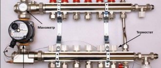
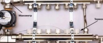
Manifold group with flow meters PF MB 802 6 outlets 1″x3/4″
1. Supply manifold 2. Return manifold 3.1. Control valve with flow meter 4. Shut-off valve 5. Adapter nipple for feed comb 6. Adapter nipple for return comb 7. Bracket 8. Automatic air vent 9. Drain valve
The manifolds and adapter nipples are made of brass with nickel-plated surfaces. All elements of the collector group are connected to each other using sealing rings made of synthetic elastomer. The brackets are made of galvanized steel.
Problems that may arise
Let's give a specific example.
Difficulties in installing the system
The length of the contours in rooms of different sizes is different. This creates problems.
- A heated floor circuit is installed in the bathroom, living room and kitchen.
- It connects to one collector.
- It is clear that the floor surface area in these rooms is different. Consequently, the length of the pipelines laid under the coating also differs.
- This means that the coolant consumption in them will also be different.
Note! In short heating rings, the level of hydraulic resistance of the tubes is lower. Based on this, water circulates in them faster than in long analogues
Consequently, at the same temperature of the liquid on the supply manifold, the floor will be overheated in some rooms, while in others it will remain cold.
The same situation can arise when using radiator heating circuits that have a different number of sections and different lengths of pipes that are connected to the same floor collector. That is, some rooms will be overheated, while others will be cold.
To prevent this from happening, the instructions recommend determining the water flow in the radiator system by installing a thermostat on each battery. In essence, it is a valve that quantitatively regulates flow. Approximately the same can be done with a floor heating system.
Ways to solve the problem
It is possible to balance the heating circuits of an underfloor heating system that are connected to the same collector group in two ways.
- When using the first of them, you need to make all the rings of equal length and correctly distribute them under the coating. For example, three circuits will be in the guest room, two in the kitchen and one in the bathroom.
- The second way is to mount only 3 circuits, according to the number of rooms. However, they will need to be connected not directly to the collectors, but through special devices - flow meters for heated floors, also called rotameters. They are intended to be balancing valves.
In the example given, the term “flow meter” does not mean a measuring device, but a special tap with which you can control and set the flow rate of the coolant.
It should be taken into account that devices from some manufacturers can only be connected to a return manifold.
Optimal design of the collector group.
- The best option is when the manifold assembly has this design - the supply manifold is equipped with a rotameter, and a thermostat is installed on the return analogue.
- Thanks to this, the supply part of the group directs a precisely dosed volume of coolant to each of the heating circuits. The return manifold closes and opens the circuits as the liquid cools in the pipes.
- In addition, it is desirable that the supply manifold for heated floors with flow meters have an automatic air vent and be connected to the return analog by a bypass having a bypass valve.
Note! Air that interferes with its operation is removed from the heating system through a vent. When it gets warmer outside, the thermostats close the circuits, at which time the bypass valve turns on and reduces the increased pressure.
At the moment, manufacturers produce many flow meters, which are both measuring devices and regulators of coolant flow. There are also devices that combine these functions. Naturally, their price is higher.
If you purchase only a measuring device, it will need to be installed together with an ordinary valve. By opening or closing the tap, according to the readings of the rotameter scale, you can regulate the flow of coolant.
How to balance heating circuits
An example of system balancing.
- The total passage of coolant through the collector (l./min.) is taken as 100 percent.
- Next (also in percentage) the consumption for each of the circuits is determined. For example - 15%, 35% and 50%. They are converted (proportionally) to liters per minute.
- Then you need to unscrew or tighten the head of the rotameter (or the tap connected to the measuring flow meter), thereby setting the required readings.
- It should be taken into account that this way only calculated balancing of the circuits can be carried out.
Assembling a manifold with flow meters.
- The actual adjustment is made based on the actual coolant flow. For this purpose, it is necessary to place a measuring rotameter in front of the supply part of the manifold for heated floors. Based on its readings, it will be possible to distribute the total costs among the circuits connected to the collector group.
Flow meters on supply or return
After all the work on laying the contours of the water-heated floor has been carried out, the crucial moment of connecting them to the collector comes.
In this article, we will look at a step-by-step sequence of how to do this correctly, when and what tests should be carried out, and what mistakes may lie in wait for you in this matter. We will also touch upon the issue of automatic temperature control in rooms.
Installation of heating pipes begins with connecting the free end of the tube to the fitting of the supply comb of the distribution manifold.
Most modern manufacturers, such as Rehau, do this using a threaded connection for a Eurocone. It is considered one of the simplest and most reliable in execution today.
Eurocone often comes with a diameter of 17mm, while a lot of users assemble their underfloor heating system from a 16mm pipe. In this case, you will have to calibrate the tube to the specified size.
You can use original cross-linked polyethylene tubes from Rehau, which are 17-gauge, then everything should work without additional movements.
Someone expands the wall using metal scissors. Everything seems to fit, but you won’t achieve perfectly even contact this way.
The reliability of the connection will ultimately suffer from this. With frequent temperature changes, it is quite possible for a leak to appear in this place in the future.
Next, put a union nut on the tube, insert a ferrule ring and a thrust bushing there.
Then hand-tighten the end of the tube to the connecting fitting.
In order not to tear off the fitting on the manifold, final tightening should be done using two wrenches. Use one to fix the hexagon on the fitting, and use the other to tighten the threaded connection.
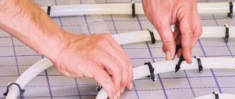
When installing elastic pipes, it is better to enclose the collector line near the floor in a rotation lock.
At the entrance to the screed, the pipes must be covered with a protective casing made of corrugated pipe or thermal insulation. The recommended length is at least 0.5 m.
25cm will go out, and the other 25cm will be located in the screed itself.
The heating circuits should be laid in increments of 100mm.
Installation of the circuit ends by connecting the other end of the pipe to the corresponding fitting of the return comb.
In the area where pipes are connected to the manifold, where the distance between the pipes is minimal or they run close to each other, they also need to be placed in thermal insulation or corrugation.
This will prevent overheating of the screed and will reduce the surface temperature near the collector itself. In exactly the same way, connect all the other circuits one by one.
It all depends on the type of rotameter. Therefore, check the documentation. In one case, the rod must be deflected downward by the flow of water, so the supply is introduced through it.
And in the other, on the contrary, raise the rod up.
You can distinguish them by the scale. For those that serve, zero will be at the very top, and the scale will correspondingly increase towards the bottom.
Those on the return line have a zero at the bottom, and the numbers increase upward.
Once connected, it’s time to fill the system with water.
This should be done not through the heating boiler, but directly through the drain and fill taps. They are located on the rear plug of the distribution manifold.
In this case, be sure to shut off the ball valves with the supply from the boiler.
Next, using a special key, close all circuits except one. This is where you will begin filling the system with water.
Also close all valves on the rotameters, except one.
Now you can connect the water hose to the drain valve on the supply comb.
A hose for draining water is connected to the return comb. After which you can slowly let the water in.
Lower the drain hose from the return comb into the sewer or simply into a bucket and wait until all the air has drained.
Time-pulse ultrasonic counters
The time-pulse method (or, in other words, phase shift) is based on measuring the travel time of a signal against the flow and in the direction of fluid movement. To convert the ultrasonic signal, two or four piezoelectric elements are installed on the pipeline, offset along the movement of water. As a rule, disk elements are used, less often - ring elements (for small diameters).
Piezo elements can be installed inside the flow (on the inner walls of a pipe or channel) or outside the pipeline (in this case, the signal passes through the outer wall). Depending on the sensors used, meters can be installed in gravity systems (both open and closed), as well as in completely closed pipelines with excess pressure of the environment. There are the following types of speed sensors:
- pipe - cut into the water supply from the outside. Can be used in pressure and non-pressure environments;
- wedge-shaped - installed on the bottom or inner wall of the pipe. As a rule, they are used in non-pressure channels or in pipelines of large diameters, if installing and servicing the sensor outside is inconvenient;
- spherical or hemispherical - mounted on inclined walls of open trapezoidal channels;
- rod - have the form of tubes, installed on the vertical walls of the channels;
- overhead – non-contact sensors, placed on the outer surface of the pipeline.
Depending on the method of installing sensors, contact and non-contact devices are distinguished. The advantage of non-contact portable flow meters is the ability to install them on pipelines without compromising their integrity. They are rarely installed permanently; they are more often used for calibration measurements at different points.
Time-pulse flowmeters are suitable for determining the flow rate of clean or slightly contaminated water (with minor inclusions of suspended particles). They are used in water supply and drainage, in cooling circuits, in irrigation schemes, at pumping pressure stations, in open natural and artificial canals and rivers. They are used for both commercial and technological accounting.
Cross-correlation ultrasonic counters
Such flow meters operate using the ultrasonic signal cross-correlation method. This technique is based on the principle of constructing velocities at different flow levels; the meter makes it possible to construct a real diagram of the distribution of velocities in the flow. The flow level is also measured.
Ultrasonic pipe and wedge-shaped speed sensors installed in the flow are used with water meters; the liquid level is determined using surface and underwater sensors. It is possible to design combined speed and level sensors.
Meters are used in pressure and gravity, open and closed systems. This is an accurate measurement method that gives reliable results for flows of varying degrees of contamination, including it is effective in heterogeneous media. Flow meters are used in process pipelines, wastewater treatment plants, rivers and reservoirs, etc. In large channels, several sensors can be installed across the entire width to obtain more accurate results.
How does a heating manifold work?
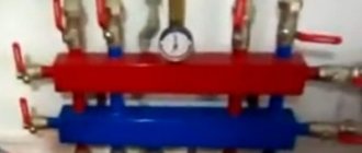
The most common horizontal version of the balancing manifold is designed like this:
At the moment, you can find many different designs of collectors on the market. The picture above shows a horizontal manifold with a hydraulic arrow, but there are vertical versions of a similar design and it looks something like this:
The essence here is similar to that implemented in the vertical design. But there is a slight difference in the piping. Here someone needs to look locally for what is more convenient. Such a collector can be made from a large-diameter polypropylene pipe. In this case, it is advisable to maintain the proportions indicated in the figure.
If you are short on space, then there is another very interesting design. It can be called coaxial:
Here two pipes are inserted into one another. In this case, the hydraulic arrow can only be connected separately.
Okay, let's talk about collectors, and now let's look at a heating system based on it. Let's move on!
Doppler method
Counters operating using this method measure the difference in wavelength reflected from a moving stream relative to the wavelength of the emitted signal. Measuring the received and transmitted signals to determine the difference between them is done using wedge-shaped or pipe speed sensors installed at the bottom of the channel or pipe.
Water meters operating on the Doppler effect are used in pressure and gravity systems, fully and partially filled pipes, and open channels. They work in streams of varying degrees of pollution (except clean water). Doppler flow meters are used for commercial metering in pipelines and gravity canals, for measuring flows in rivers and canals of irrigation systems, in storm sewers, at pumping stations, water intake pipelines and discharge of wastewater into reservoirs.