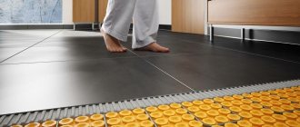
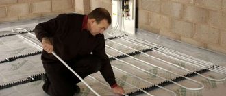
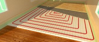
One of the best ways to ensure a comfortable temperature in a house or apartment is to install a heated floor system. This system itself consists of many elements, each of which is integral and important. But a special place among them is occupied by the distribution comb, also known as the underfloor heating manifold. Without it, the system cannot function normally and provide its owners with high-quality and comfortable heating of residential premises. Let's look at what a comb for a heated floor is, how it is designed and by what principles it works.
Comb for heated floors
Why a comb is necessary
The story about the distribution comb should begin with the role of this unit in a warm floor and with an explanation of why it would be impossible to ensure normal operation of the system without it. You can see a simplified diagram of such heating in the image below. The coolant, which is ordinary water, comes from the boiler (or a centralized heating main, if we are talking about a city apartment) to the collector unit, where it is mixed with the liquid that circulated in the system previously. Then the water flows along the contours laid under the floors and gives off its heat to them.
Simplified diagram of a heated floor system
As a rule, the real scheme of a heated floor is more complex than the one in the image above - there are several contours, and they have different lengths of pipes. Accordingly, they need different amounts of coolant. But if hot water comes from a source in the form of a boiler or main without any distribution, then most of it (water) will rush into the smallest circuit. As a result, there will be overheating. Conversely, on large circuits there will be a lack of heat.
A diagram illustrating the location of underfloor heating circuits in various rooms of the house. You can see that they differ greatly in their area and the location of the supply and discharge lines
Important! The presence of a correctly adjusted comb solves this problem - the water flow in each individual section of the heated floor is set in accordance with the need for coolant. At the same time, both a small bathroom and a large living room will be heated equally well.
The comb for heated floors has another function - reducing the water temperature to a level acceptable for the circuits. The coolant from both the boiler and the central line is supplied very hot, about +70-80 or even more degrees - making the temperature lower is unprofitable in terms of fuel consumption. But such a liquid is not suitable for heated floors. This means that it must be cooled by mixing it with already cooled water from the “return” of the heating circuits. This happens inside the underfloor heating comb. Using sensors and valves connected to them, the manifold maintains the temperature at a certain level set by the user of the system.
Distribution comb (collector) for warm water floor
Servo driven comb
Connection methods
You will need the following materials and devices:
- Pipeline;
- Pipeline components;
- Boiler;
- Three-way thermostatic valve;
- Pump assembly.
Some people try to use the simplest installation method - to embed the underfloor heating system directly into the central heating system. However, this approach threatens serious damage to the pipeline, because The temperature for radiators is much higher than that needed for the floor. Also, if such a “homemade device” is discovered by supervisory authorities, the owner of the apartment faces serious penalties and an order to completely dismantle the warm water floor.
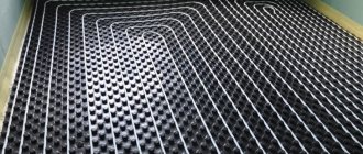
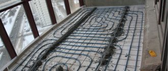
Options for laying a pipeline without a collector : snail and snake. Moreover, both schemes must consist of a double pipeline: 2 parallel loops to the heated floor - supply and return.
- The advantage of the “snake” is that you can distribute heating zones. For example, go around furniture or plumbing fixtures.
- The advantage of the “snail” is more uniform heating of the entire area.
After laying the pipeline, it must be connected to the boiler. You must first calculate the pump power. The following formula is used:
G =Q X 0.86/Δt,
where G is the system capacity (l/h),
Q - system power (W),
0.86 — conversion factor in Kcal/h,
Δt—flow-return temperature difference (°C).
A pump is needed to ensure the speed of coolant movement through the pipes. Depending on the type of pump, it can be controlled either manually or automatically. The device is mounted on the supply pipeline. In a system without a mixing unit, the pump device is located under the boiler. The circuit between the pipeline with the pump and the boiler is closed by a three-way thermostatic valve.
In order for the heated floor to work stably without installing a mixing unit, you should choose a high-quality, powerful boiler. Electric or gas – it doesn’t really matter. The main thing is that the power of the device is designed specifically for the designed heated floor. Experts recommend choosing models with a pump.
How the comb assembly for heated floors works
A comb for heated floors can be divided into the following components:
- supply manifold;
- return manifold;
- fasteners for assembly and installation;
- shut-off valves for supply and return from the boiler;
- thermometer;
- drain tap;
- a device for releasing air from the system (also known as a Mayevsky valve);
- mixing manifolds for supply and return;
- pump;
- valve for supplying coolant from the boiler to the comb.
Comb device for heated floors
Now let's look at them separately. The supply manifold is a horizontal pipe with several branches - two or more. From it the coolant flows into the heated floor circuits. The supply manifold is equipped with flow meters - devices that help regulate the volume of water entering a particular element of the system. To do this, the flow meter changes the cross-section at the branch from the collector to the circuit.
Feed manifold
The “return” collector is similar in appearance - it is also a horizontal pipe with branches. But here, instead of flow meters, thermostatic valves, also known as thermal heads, are installed. With their help, the user can regulate the temperature in individual areas of the heated floor.
Return collector
Both collectors are secured with two mounting brackets . They, in turn, are attached to the wall at the location where the comb for the heated floor is installed.
The supply circuit (bottom) and return circuit (top) are together, assembled and fixed on mounting brackets
Shut-off valves are used to completely shut off the supply and return lines going to the heated floor comb from the heating boiler or centralized main.
Important! When installing such a heating system, place a bypass in front of the comb and shut-off valves. Without it, when the supply to the underfloor heating manifold is cut off, there is a risk of overheating and failure of the boiler.
Ball valve
A thermometer is necessary to monitor the temperature in the manifold system for underfloor heating. The drain valve is used to discharge water for the purpose of repair and maintenance of the unit. And the Mayevsky valve is required to bleed air from the underfloor heating pipelines - if it (air) is present, the liquid may stand up in one of the circuits and the heating efficiency will sharply decrease.
The coolant in such a heating system cannot move properly on its own, so a pump . And finally, the comb is complemented by various fittings, angles and tees, connecting all the elements into a single product and ensuring the movement of water from the boiler to the supply manifold and from the outlet to the “return”.
Pumping and mixing unit for heated floors
To maintain the temperature in the heated floor at the proper level, you need to add a little very hot water from the boiler or centralized line to the circulating coolant. For this purpose, a supply valve is built into the comb, which can be two- or three-way. You can learn about the principles of their operation in the subsections below.
Why are distribution manifolds needed for water heated floors?
Operating principle of a heated floor comb with a two-way valve
A two-way valve is installed in the system directly in front of the heated floor comb. At the same time, it is equipped with a remote temperature sensor, which, as a rule, is located next to the “return” manifold. The valve has two states (open and closed), which are determined by the position of the rod, which, in turn, is controlled by the thermal head.
The principle of operation of such a system is as follows: first, the two-way valve is open, liquid from the boiler with a high temperature enters the comb. There, already cooled water from the “return” is mixed with the liquid and this mixture is sent to the supply manifold. In this case, a remote sensor measures its temperature. If it is still below the set value, the two-way valve remains open. If the water warms up to a certain temperature or even exceeds it, the device closes and the flow of coolant from the boiler stops. The liquid in the underfloor heating system circulates independently.
Detailed wiring diagram for a heated floor boiler (with a two-way valve)
But over time, giving off heat to the room, it will cool to a temperature that is lower than normal. In this case, the thermal head of the valve, taking into account the data from the sensor, will raise the rod - the valve will open, and very hot water from the boiler will again be mixed with the liquid in the comb. The balancing valve shown in the image below is necessary to regulate the volume of “return” that will be mixed with the coolant.
A two-way valve is a fairly reliable system in which the likelihood of the locking element breaking and excessively hot water entering the heated floor is minimized by the presence of a thermostat and the very principle of operation of the device. But at the same time, the accuracy and smoothness of regulation are inferior to the scheme with a three-way valve.
Mixing unit with two-way valve
Important! It is also worth saying that a comb with a two-way valve has a limitation in area - it can heat no more than 150-200 m2 of residential premises. As a rule, the device’s performance is not enough for more.
Distribution manifold for heated floors
Operating principle of a heated floor comb with a three-way valve
Now let's look at the operating principle of this unit with a three-way valve. As can be understood from the name, this control device has not two, but three inputs - the supply from the boiler is connected to one, the outgoing collector is connected to the second, the line from the return collector with already cooled water is connected to the third. For better clarity, we will present the work process step by step.
Connection diagram with three-way valve
Step 1. Initial position, on the three-way valve the mixing line is completely closed and the supply from the boiler is open. Hot coolant enters the comb.
Step 2. The sensor located in the comb gives a signal when the temperature is exceeded. The valve shut-off element moves, partially opening the mixing line and closing the supply line. The already cooled liquid from the return line of the heated floor is added to the hot water from the boiler. And the more the coolant temperature is higher than normal, the more the supply from the boiler will be shut off and the mixing line will be open.
Step 3. The coolant temperature has returned to normal, the shut-off element of the three-way valve remains in its current position.
Step 4. The coolant temperature drops after several cycles of passage through the circuits. Information about this is received by the valve from the sensor, the shut-off element closes the mixing line and completely opens the supply of hot water from the boiler. The cycle repeated.
Three-way mixing valve and its position on the diagram for connecting the comb to the boiler
A more visual representation of the connection diagram for a three-way valve between the boiler and the underfloor heating comb
A simplified diagram of how the coolant supply in a three-way valve is regulated and how colder water is mixed into it
According to this principle, the three-way valve constantly regulates the temperature of the coolant, and mixing is carried out not directly in the comb, as in the previous scheme, but in front of it, in the valve itself.
Such a system has the best indicators of smoothness and accuracy of regulation. In addition, it can effectively “cook” water for heated floors with an area of 150 m2 or more. But at the same time, a three-way valve is less reliable than a two-way valve - there is a risk that the control element will fail. And if it remains in a position in which the supply of very hot water from the boiler is constantly open, then damage to the underfloor heating pipelines is possible.
Photo of a warm water floor comb
Features of connecting a heated floor without a mixing unit
A common mistake when installing a system without a mixing unit is installation in a very large room.
Basic installation requirements:
- The walls in the room must be insulated (outside or inside);
- The floor must be insulated;
- High-quality double-glazed windows;
- Installation of the floor close to the heating system;
- The area of the room is no more than 25 m2.
Disadvantages of a system without a collector:
Large heat losses along the path from the heating device and the pipeline unit itself. Accordingly, it is necessary to conserve heat on the floor surface.
A competent calculation of the length of the circuit and circuit is necessary so that the return temperature indicator is not too low. Otherwise, during the heat exchange of the boiler, a lot of condensate will form, which can quickly damage the device.
Installing a condensing boiler with high efficiency helps with cold “return”; the device is not affected by low temperatures when heating.
Assembly methods
The elementary principle of assembly is to connect the underfloor heating structure to the central heating. The disadvantage of such a system is the risk of breakdowns of the underfloor heating pipeline due to the supply of high water temperature to the radiators.
A self-built structure that is connected to a central heating point may be fined and dismantled by supervisory authorities upon detection.
The two best ways to lay pipes without a mixing unit:
- the snake helps distribute heating areas (bypass furniture or plumbing fixtures);
- The snail promotes uniform heating of the floor area.
Both methods must be constructed of a double piping system for supplying and returning water.
After the pipeline is laid, it is connected to the boiler. A pump of the required power will ensure the speed of movement of the heating element through the pipeline.
Pump models come in manual and automatic control . The device is placed on the supply part of the pipe. If there is no collector in the system, the pump is located under the boiler.
The connecting structure is completed by a valve, which should be installed between the pipe and the pump.
For stable operation of a heated floor without a collector, it is recommended to choose a high-quality electric or gas boiler with high power.
It is better to purchase a boiler complete with a pump .
Differences between radiator heating designs and water heated floors
- Radiator heating is characterized by high coolant temperatures, the supply temperature is approximately 70 degrees, and the return temperature is 50 °C. Installation features - the pump is not installed on the supply side to eliminate the possibility of overheating.
- The floor temperature during heating should be no more than 26-30 °C; a comfortable temperature for gentle operation of the pump is 40 °C.
- The circulation speed of radiator heating is not high; due to the temperature difference, it will be enough to install a boiler with a pump built into it.
- Thin plastic pipes serve as a radiator for a warm water floor. The length of pipes can reach more than one hundred meters in one installation system. Accordingly, the pumping device must be powerful in order to push water through the pipeline.
Three way valve system
The thermostatic valve (three-way) is assembled onto the heat supply pipes, and a jumper is connected to the opposite flow.
This device regulates the temperature of the heat supply, which is supplied to the pump. The valve functions as a mixer with a temperature-sensitive element.
The advantages of the valve are that it protects the system from too high temperatures (overheating) and, if necessary, during a breakdown it will automatically shut off the supply of coolant and return flow. Thanks to this, the valve takes on part of the work of the mixing unit.
When the floor area is too large, large heat losses can occur when the coolant returns. Therefore, it is better to install a valve on the edge with a cold inlet; this will give the effect that there is no excess condensate in the heat exchange device.
Choosing a pump
Is it possible to do without a mixing unit? It's possible, but it's unlikely without a pump. The circulation station will increase the pressure and heat the water evenly, will not create excess pressure, and will push the water at the required speed.
Before choosing a pump, you need to decide on the company, model, and material from which it consists.
For use in domestic conditions, it is recommended to use two types of equipment:
- Glandless rotor pump . This technique does not have much power, but can provide heated floors with an area of 350-400 m2. The rotor is called “wet” because the wheel is located in the coolant; cooling and lubrication occurs when it is used. The device is popular due to its quiet operation, reliability and economical energy consumption.
- The model with a dry rotor is a fairly powerful device in which the rotor is located in an impenetrable container. This type of equipment is used for arranging fountains in private homes or park areas. The model requires periodic maintenance.
Choosing a comb for heated floors
Separately, it is worth mentioning how to choose the right comb for a heated floor. In this case, you should pay attention to the following criteria:
- the material from which the supply and return manifolds are made;
- the number of circuits on the manifolds in the comb, the permissible level of pressure and water flow;
- degree of automation of the product - what sensors are present in the comb, are there thermostats and other electronics for fine-tuning the temperature in the heated floor circuits;
- manufacturer of combs for heated floors.
Choosing a comb for heated floors
Now we will reveal each of the points in more detail. Let's start with the material from which the comb is made.
Table. Materials used in the production of combs for heated floors.
| Material | Description |
| Brass | Combs for heated floors from this material are made by casting. The result is a fairly strong and durable part, but at the same time expensive. If the price of a comb is not a problem for you, then you should pay attention to brass products. |
| Stainless steel | It is made by welding (followed by careful sealing of the seam). Its strength is similar to brass products, but a stainless steel comb can be subject to electrochemical corrosion. |
| Plastic | Cheap combs made of high-quality plastic that is resistant to high temperatures and pressure. Their quality is almost equal to that of metal products. |
comb for heated floor
Having decided on the material, proceed to consider other parameters of the comb. And the most important of them is the number of taps on the collectors. Ideally, it should be equal to the number of circuits in the floor heating system. But combs with a large number of outlets are also allowed - in this case, plugs must be used. Even before purchasing, it is advisable to make simple calculations and determine what pressure and fluid flow will be in your system. The comb must be suitable for the conditions in which it will work. In this case, it is desirable to have a certain “margin of safety” in case of a sharp increase in pressure or coolant flow in the system.
Assembly of the collector unit in the case of a combined system: radiators + heated floor
Next, you need to decide what degree of automation and temperature and flow control you need. Today on the plumbing market there are technically advanced combs that can be connected to thermostats and programmable controllers. With their help, you can constantly adjust the temperature and flow on the circuits in accordance with the weather outside and the needs of the residents. At the same time, the high price of the product is compensated by additional savings on coolant.
A set of combs for heated floors with automatic regulation using a set of temperature sensors placed directly in those rooms that are heated
And finally, always pay attention to the country and manufacturer. As a rule, combs for heated floors made by European companies are of better quality, but also more expensive. An alternative to them may be domestic and Chinese devices, which are inferior in their durability and reliability, but at the same time are much more affordable for the common buyer.
Important! When purchasing an expensive comb for heated floors, make sure that it is not a counterfeit masquerading as a well-known company with a good reputation. To do this, it is advisable to familiarize yourself with the various certificates that the seller of this product must have.
The comb or collector of the heated floor is located in a special cabinet (mounting box)
Warm floor without collector.
Manifolds for heated floors cost a lot of money and for this reason many people try to avoid buying them. Standard manifolds are being replaced by homemade ones made from polypropylene tees or, at best, from manifolds with shut-off valves, which are designed for wiring a radiant radiator heating system. They look like this:
Homemade polypropylene manifold.
Manifold with shut-off valves.
Their main difference from standard ones is the absence of flow meters. Many “self-taught” people tell me that they have done everything without them 100 times and everything works. But at the same time they do not specify that it is impossible to achieve the same temperature in the circuits. This effect appears due to the fact that water, as an electric current, tends to follow the path of least resistance, which means that through shorter circuits the coolant flow will be greater than through longer ones. Flow meters are precisely what is needed to see through which circuit the flow rate is greater. The flow through the circuits is equalized using balancing valves, which are located on the return manifold. It is almost impossible to balance circuits without flow meters! You will receive the VTP inertial system and the response from turning the valve in at least a few hours. At the same time, individual flow meters are very expensive. This was done, in my opinion, specifically to force the consumer to buy manifolds, and not spare parts for them. Now let's look at another non-standard version of the OBE.
Assembling a factory comb for heated floors - step-by-step instructions
Most often, factory-made combs made of stainless steel or brass are used for underfloor heating systems. Using the example of one such device, let's look at the step-by-step assembly process.
Step 1. Unpack the comb and all its component parts. Check the integrity and completeness in accordance with the attached instructions.
Unpacking the comb
Step 2. Lay out all the components of the manifold assembly on the floor or other flat and level surface in accordance with how they should be assembled.
The elements of the assembly are laid on the floor
Step 3. Assemble together the individual small elements of the heated floor comb. In this case, a thermometer and a valve are assembled to shut off the supply to the manifold from the boiler.
Connection of thermometer and stopcock
Step 4. Connect the small elements of the heated floor comb assembled together to the supply and discharge manifolds in accordance with the instructions.
Next, small elements need to be connected to the collectors
Step 5. Unpack the brackets for attaching the heated floor comb to the wall. Check the contents.
Mounting brackets unpacked
Step 6. Fix the comb manifolds to the brackets by installing them on the large brackets and securing them on top with the small ones.
Collectors are fixed on brackets
Step 7. Drill holes in the wall and mount the manifolds along with shut-off valves, thermometers, drain valves and air vents on the wall. Next, install the two- or three-way control valve, pump and other products that are necessary to create a complete comb set.
Screwing collectors to the wall
Video - Manifold for heated floors
DIY comb for heated floors
An alternative to a factory-made heated floor comb can be a product that you assemble yourself. As a rule, in this case, shut-off valves, various sensors and other complex elements of the system are purchased separately, and the supply and return manifolds are made by hand from polypropylene pipes. Let's look at a little step-by-step instructions for this process.
Step 1. Prepare materials and tools. First of all, you will need polypropylene pipes designed to work at high temperatures, and the same tees. In addition, take fittings for connecting shut-off valves, thermal heads and pipes of the heated floor system. As for the tools, you will need a tape measure, scissors for polypropylene pipes and a soldering iron for them with a set of nozzles of different sizes.
Preparing everything you need
Important! Remember that a soldering iron for polypropylene pipes heats up to high temperatures. Therefore, to avoid getting burned during work due to negligence, use protective gloves.
Step 2. Heat the soldering iron to the desired temperature, prepare a pipe and tee from polypropylene. Clean and degrease their edges to ensure high-quality soldering of the elements.
Preparing the pipe and tee
Step 3. Place a fitting on one side of the soldering iron caliber (its inner surface should be heated) and a polypropylene pipe (here it’s the other way around - you need to heat up the outer one). Keep them like this for some time.
The connected elements are kept for some time
Step 4. After this, take and connect the polypropylene pipe and tee together. At the same time, try not to rotate them relative to each other.
The pipe is connected to a tee
Step 5. Trim the pipe to leave only a small section of it necessary to secure the next tee as part of a homemade polypropylene manifold.
Pipe cutting
Step 6. Using the same principle, connect the following fittings with polypropylene pipes.
Connecting other fittings to pipes
Step 7. Complete the creation of a comb for a warm floor with your own hands by securing couplings for connecting pipes from the circuits, shut-off valves and an air release valve. The image below shows the finished product, designed to distribute the coolant into two sections of the heated floor.
All is ready
Single-circuit boiler and heated floor
The main requirements for a heating system are stability and efficiency.
…
All these requirements are met by autonomous heating with a gas boiler and a “warm floor” system.
The article discusses methods for installing a “warm floor” with a gas single-circuit boiler.
Advantages of using a single-circuit gas boiler and a “warm floor” system
The following advantages can be identified in using a single-circuit boiler and heated floors:
- the ability to set the temperature in the rooms;
- assigning a heating season schedule;
- economical operation of the heating system due to the high efficiency of gas boilers.
Selecting a single-circuit gas boiler for a “warm floor” heating system
It is very important to choose the right power of the unit. If the power is insufficient, the heating of the room will be of poor quality.
…
A large reserve of maximum power of the unit will not be advisable: overpayment for equipment and inefficient operation of the unit at low power.
On a note. To increase the functionality of a single-circuit boiler, an indirect heating boiler can be included in the circuit. It will heat water for domestic needs.
Types of single-circuit boilers
Depending on the type of installation, boilers are:
- wall or hanging;
- floor or stationary.
Single-circuit wall-mounted gas heating boilers are economical and compact low-power units, up to 35 kW (kilowatt). They are very convenient for heating small spaces, as they are hung on the wall and take up virtually no space.
Wall-mounted boilers contain all the necessary elements in their compact body: burner, heat exchanger, circulation pump, air vent and other equipment. Such units are called mini-boiler rooms.
Stationary heating boilers are installed on a special stand. Their feature is a wide power range. Domestic models are limited to 120 kW, and industrial boilers produce more than 1000 kW of heat load.
…
According to the design of the combustion chamber, boilers can be:
- Atmospheric ones are units with an open combustion chamber. Natural draft is required to remove combustion products. It is carried out by installing a chimney of a certain size.
- Turbocharged engines are units with a closed combustion chamber. The draft in them is created using a fan (smoke exhauster).
On a note.
To install a gas boiler directly in a living area, a boiler with a closed combustion chamber is best suited. Its operation does not affect air quality and there is no need for a chimney. Arrangement of a separate room is not required. Wall-mounted units are usually equipped with a closed combustion chamber.
The operating life of a gas boiler directly depends on the type of heat exchanger. Heat exchangers are made of steel, cast iron and copper.
The steel heat exchanger tolerates temperature stresses from the flame well, but is susceptible to corrosion. This is a good budget option.
The cast iron heat exchanger is not subject to corrosion, but is very “capricious” in maintaining the temperature regime, since it does not tolerate temperature imbalances between the supply and return lines. The disadvantage is the heavy weight.
The copper heat exchanger has the highest efficiency compared to others due to its high thermal conductivity. Very light. The disadvantage is instability to temperature stresses from flames, due to this it has a short service life.
Calculation of heating boiler power
To select a boiler for a “warm floor” heating system, you can use the following data:
- Heating area 250-450 sq. m – boiler power 36 kW.
- Heating area 220-350 sq. m – stake power 30 kW.
- Heating area 140-300 sq. m – boiler power 12-24 kW.
- Heating area up to 70 sq. m – boiler power is about 6 kW.
- Heating area up to 30 sq. m – boiler power no more than 6 kW.
The heating system consists of several elements:
- hot water boiler;
- connecting pipes;
- distribution manifold;
- "warm floor" coil;
- fittings;
- circulation pump.
Polypropylene or cross-linked polyethylene can be used as a material for piping a single-circuit boiler in a “warm floor” heating system. The main requirement for pipes is the ability to withstand temperatures up to 950C. and pressure up to 10 bar.
The distribution manifold has the function of uniformly distributing the coolant between several “warm floor” circuits. This is a regular large diameter pipe with many outlets. The number of taps depends on the number of circuits.
On a note. If you install shut-off valves at each collector outlet, you will be able to turn off each heating circuit individually without affecting the operation of the heating system as a whole.
The water heating system must be equipped with a safety group. This is a set of protective elements: pressure gauge, safety valve, air vent and expansion tank.
The diagram shows a gas boiler. It heats the coolant, which then enters the supply line connected to the distribution manifold.
From the collector, the coolant enters the heating circuits. From the underfloor heating coils, the cooled water is collected in the return line manifold and pumped back to the boiler.
On a note. To ensure automatic temperature control, you can install a room thermostat for a gas boiler.
A gas boiler and underfloor heating system will make your home warm and cozy without unnecessary worries.
Setting up a comb for heated floors
After assembly, installation and connection, the comb for a warm floor must be configured - set the required level of temperature and water flow for each individual circuit. With the first parameter, everything is solved very simply - on the thermal head, located at the corresponding outlet in the “return” manifold, the required temperature level is set by scrolling.
With setting the flow rate, everything is much more complicated - each circuit has its own length, and there are no general patterns for adjustment. The fastest way to do this is to perform a hydraulic calculation of sections of heated floors using software that you can get on the website of one of the comb manufacturers.
The flow meter on the supply line in the manifold is equipped with an indicator flask. Under it there is a nut, by unscrewing or tightening which you can increase or decrease the coolant flow rate on the circuit
Hydraulic calculation of the heated floor circuit, on the basis of which you can calculate the flow rate and set it on the corresponding branch of the comb
But if for some reason you do not want to deal with adjusting the flow rate, then there is a simpler, but time-consuming method. It lies in the fact that the adjustment is carried out “by feeling” - if the room is too cool, then the flow rate at the collector increases, if the floor is too hot, then, on the contrary, it decreases. But due to the general inertia of the system, such a process can be seriously delayed. In addition, it must be taken into account that without a preliminary hydraulic calculation it will be impossible to immediately achieve an optimal result.
However, the process of adjusting the flow and temperature of a heated floor is not complicated in itself - you just need to twist the flow meter and thermometer on the supply and return manifolds in the right direction.
Warm floor without screed.
Owners of two or more storey houses with wooden floors are most often interested in this option of HTP. Screed is not poured on a wooden floor due to the heavy load on the structure, and here the question arises of how to implement a water-heated floor without a screed. There may be two options here:
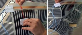
- Laying an electric heated floor - most often a film TP is laid under the laminate, and for bathrooms you can use mats that are laid in a layer of tile adhesive.
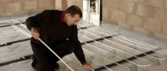
- VTP flooring system - here the pipe is laid between the joists, which are placed on the subfloor. To improve surface heating, special reflective metal plates are used. Most often, thick aluminum foil is used for this. It looks like this:
If you save money and do not use reflective plates, the “zebra” effect will appear. That is, certain areas of the floor will be warmer than others. Laying pipe loops this way is, of course, more difficult. You will have to cut grooves in the boards into which the pipe will be laid, but I don’t know of any other option for VTP for wooden floors. The heat transfer of such floors will be slightly worse than that of concrete floors. It will be problematic to use them for main heating. In addition, they will have less inertia, that is, a switched-off VTP will cool faster than a concrete one, but it will also heat up faster. You can watch the following video for a better understanding of the process:
