Here you will learn:
- The principle of operation of the collector
- Positive and negative aspects of the collector circuit
- Types of collectors in heating systems
- Feed and return manifold comb device
- Collector heating system - general principles for designing wiring diagrams
- Installation and connection rules
- Rules for selecting distribution manifolds
- We manufacture a distribution manifold
The collector is a volumetric comb.
It works like this:
- water flows inside;
- through special exits it is carried through the pipes.
A collector works in a similar way, collecting cooled water from several pipes into one and subsequently redirecting it to a common boiler. You can connect different heating devices to such an assembled group, regardless of their technical parameters.
The size of the distribution manifold depends on the number of circuits - pipes connecting to it. In the vast majority of cases, the largest number of circuits is 12. The collector then consists not of one comb, but of two - 6 circuits on each. If it is necessary to obtain a larger number of circuits or a single comb rather than a pair, then some manufacturers manufacture custom-made manifolds.
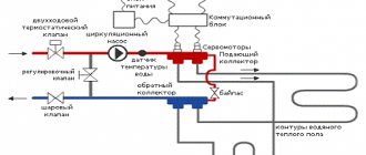
The principle of operation of the collector
As for the principle of operation of the collector, everything is quite simple. The heat generator that heats the water releases the liquid to the supply comb. At this intermediate node, the speed of the coolant flow slows down significantly, which is facilitated by a larger radius. This allows water to be distributed over several outlets.
Once you know how much coolant is consumed when heating an apartment (house) along all circuits, all that remains is to select the required power of the heat generator (boiler) and the speed of the fluid flow, after which the cross-sectional area will be known. When making calculations, be sure to convert liters to mm3.
In order for the coolant to flow to devices that radiate heat into the premises, pipes of a slightly smaller cross-section are used on the collector block, through which the liquid reaches individual parts of the circuit, gradually falling into the radiator or onto the heated floor grid. Due to this design, each element of the heating system, to which the collector block is connected via a circuit, is heated to the same temperature.
When liquid enters a radiator or heated floor, it gradually gives up its heat, and then moves back along a different path, reaching the distribution unit of the collector block. Here the reverse comb is activated, directing the cooled coolant to the boiler or other generator for reheating.
Operating principle and types of solar collectors
The time has come to say a few words about the design and operating principle of the solar collector. The main element of its design is the adsorber, which is a copper plate with a pipe welded to it. Absorbing the heat of the sun's rays falling on it, the plate (and along with it the pipe) quickly heats up. This heat is transferred to the liquid coolant circulating through the pipe, which in turn transports it further through the system.
The ability of a physical body to absorb or reflect solar rays depends, first of all, on the nature of its surface. For example, a mirror surface perfectly reflects light and heat, but a black surface, on the contrary, absorbs it. That is why a black coating is applied to the copper plate of the adsorber (the simplest option is black paint).
The principle of operation of the solar collector
1. Solar collector.2. Buffer tank.3. Hot water.
4. Cold water.5. Controller.6. Heat exchanger.
7. Pump.8. Hot flow.9. Cold flow.
You can also increase the amount of heat received from the sun by correctly selecting the glass covering the adsorber. Regular glass is not transparent enough. In addition, it glares, reflecting part of the sunlight falling on it. In solar collectors, as a rule, they try to use special glass with a low iron content, which increases its transparency. To reduce the proportion of light reflected by the surface, an anti-reflective coating is applied to the glass. And to prevent dust and moisture from getting inside the collector, which also reduce the throughput of the glass, the housing is made sealed, and sometimes even filled with inert gas.
Despite all these tricks, the efficiency of solar collectors is still far from 100%, which is due to the imperfection of their design. The heated adsorber plate radiates part of the received heat into the environment, heating the air in contact with it. To minimize heat loss, the adsorber must be insulated. The search for an effective way to thermally insulate an adsorber led engineers to the creation of several types of solar collectors, the most common of which are flat and tubular vacuum.
Flat-plate solar collectors
Flat solar collectors.
The design of a flat solar collector is extremely simple: it is a metal box covered with glass on top. Mineral wool is usually used to insulate the bottom and walls of the housing. This option is far from ideal, since heat transfer from the adsorber to the glass through the air inside the box cannot be ruled out. With a large temperature difference between inside and outside the collector, heat loss can be quite significant. As a result, a flat solar collector, which functions perfectly in spring and summer, becomes extremely ineffective in winter.
Design of a flat solar collector
1. Inlet pipe.2. Protective glass.
3. Absorption layer.4. Aluminum frame.
5. Copper tubes.6. Heat insulator.7. Outlet pipe.
Tubular vacuum solar collectors
Tubular vacuum solar collectors.
A vacuum solar collector is a panel consisting of a large number of relatively thin glass tubes. An adsorber is located inside each of them. To prevent heat transfer by gas (air), the tubes are evacuated. It is precisely due to the absence of gas near the adsorbers that vacuum collectors are characterized by low heat loss even in frosty weather.
Vacuum manifold device
1. Thermal insulation.2. Heat exchanger housing.3. Heat exchanger (collector)
4. Sealed plug.5. Vacuum tube.6. Capacitor.
7. Absorbing plate.8. Heat pipe with working fluid.
Positive and negative aspects of the collector circuit
When planning the installation of heating with collector wiring, you should carefully study the technical side of the issue and determine all the positive and negative qualities of this system. Taking these qualities into account when building a house, you will be able to achieve its greatest energy efficiency.
Positive qualities of the collector system:
- direct control of each individual radiator of the system;
- a differentiated approach to heat distribution in each room, which makes it possible to effectively maintain the required temperature throughout the house, while saving money;
- ease of operation, the ability to access each component of the system without interfering with the operation of the others;
- aesthetic component, which consists in the possibility of installing the pipeline and auxiliary components of the system in the wall or floor;
- high payback associated with efficient consumption of energy resources.
Negative qualities: high costs at the initial stage of design and installation associated with the need to use pipes and additional components;
As you can see, there are not many disadvantages, they are not significant in comparison with the advantages of the system. Therefore, a collector heating system is rightfully considered the best solution today.
Types of collector units
Before considering the types of combs, we will indicate ways of their use in water heating systems of private houses and apartments:
- distribution and regulation of water temperature in underfloor heating circuits, abbreviated as TP;
- distribution of coolant to radiators using a radial (collector) circuit;
- general heat distribution in a large residential building with a complex heat supply system.
On the left in the photo is a coplanar manifold for distributing the coolant among the branches, on the right is a ready-made collector module with a hydraulic switch.
In country cottages with branched heating, the collector group includes a so-called hydraulic switch (otherwise known as a thermo-hydraulic separator). Essentially, this is a vertical manifold with 6 terminals: 2 from the boiler, two to the comb, one on the top to remove air, and water is discharged from the bottom.
Addition. There are cascade water guns with a large number of fittings where the heating circuits are connected directly. Then the manifold type distributor is not used.
Now about the types of distribution combs:
- To limit water temperature, regulate flow and balance heating floor circuits, special collector blocks made of brass, stainless steel or plastic are used. The size of the connecting hole of the main heating main (at the end of the pipe) is ¾ or 1 inch (DN 20–25), the branches are ½ or ¾, respectively (DN 15–20).
- In radiator beam circuits, the same combs of underfloor heating systems are used, but with reduced functionality. We will explain the difference below.
- For general house distribution of coolant, large steel collectors are used, the connection diameter is over 1” (DN 25).
Factory manifold groups are not cheap. To save money, homeowners often use hand-soldered polypropylene combs or buy cheap distributors for water supply systems. Next we will indicate the problems associated with the installation of homemade and plumbing manifolds.
Combs for radiator and floor systems – made of stainless steel, brass and plastic
Types of collectors in heating systems
Collector installations used in the design of closed circulation heating systems come in three varieties.
Depending on the purpose of the design, the following are available on the market: radiator and solar systems, as well as devices equipped with a hydraulic arrow.
Radiator collector heating
Whatever type of heating is designed in the house, radiators are always present in it. Therefore, collectors that distribute coolant flows directly to batteries installed in rooms are the most popular type.
The distribution unit consists of two interconnected combs: the first directs the coolant to the appliances installed in the rooms, the second takes it back to the boiler
Collectors used for radiator heating, depending on the architectural and interior features of the room, can be connected in various ways.
According to the connection method, the radiator heating system can be made in any of the following versions:
- top connection;
- bottom connection;
- side installation;
- leading diagonally.
The lower connection method is still the most widespread. With such a layout, the contours hidden under the surface of the baseboard or floor are not so striking.
And calculations confirm that with a lower connection, all the advantages of private heating are fully manifested.
Each floor of the house is equipped with a collector for radiators. Install it in the center, masking the device in a niche or in a cabinet specially built for it on the wall.
The installation location should be chosen so that, if possible, branches of equal length are supplied to all devices.
If it is impossible to achieve equality of the rings connected to the collector, then each outlet is equipped with its own circulation pump.
In fact, all branches connected to the distribution node represent an independent circuit with its own shut-off valves, and sometimes automation.
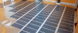
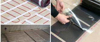
A striking example of a collector heating scheme is water heated floors.
The collector wiring diagram ensures a uniform supply of heat to all rings of the water-heated floor system.
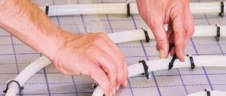
Underfloor heating pipelines are assembled from copper pipes or their plastic analogues; permanent fittings are used for connections.
Valves are installed in the heating rings, with the help of which they regulate the supply of coolant, and, if necessary, disconnect the “warm floors” from the general heating network.
A “warm floor” manifold is a structure that includes a series of pipe rings, which is laid under the floor covering
Such systems are always equipped with a circulation pump. It is placed in an intermediate collector unit at the entrance to the return pipe.
The number of pipes on the distribution unit depends on the number of rooms connected to one comb.
The number of collector groups is determined based on the length of the circuits. The calculations are based on the ratio in which 120 meters of pipeline are allocated to one collector group.
Hydraulic boom
When installing powerful and extensive heating systems, which are designed in residential buildings with a large area, distribution manifolds equipped with a thermo-hydraulic distributor or hydraulic switch are used.
When installing a connecting link, a heating boiler circuit is connected to it on one side, and radiator heating or “warm floors” on the other.
The hydraulic arrow is a vertical hollow pipe equipped at the ends with elliptical plugs, the main purpose of which is to equalize the pressure exerted on the coolant
The presence of a hydraulic distributor allows you to solve several problems at once:
- avoid sudden changes in temperature in the pipes, which have a detrimental effect on the service life of the system;
- by mixing and secondary circulation of part of the coolant, maintain a constant volume of boiler water, as well as save fuel and electricity;
- if necessary, compensate for the flow deficit in the secondary circuit.
Maintaining temperature balance is achieved due to the fact that the device allows you to separate the hydraulic circuit of the boiler from the secondary circuit.
Option for manufacturing a homemade manifold distributor, equipped with a hydraulic arrow, which is made of a steel square pipe and equipped with fittings
Optimal operation of a system equipped with a hydraulic arrow can be ensured if each circuit is equipped with its own circulation pump.
Solar collector installations
Devices of this type are chosen when installing an autonomous water supply system in non-gasified areas where the level of solar radiation is quite high.
Solar-powered air combs operate through the greenhouse effect, converting sunlight into thermal energy
The design of solar installations is slightly different from traditional counterparts. In essence, they are a kind of greenhouses that accumulate solar energy.
The natural circulation of the coolant in them is carried out due to convection currents and under the action of fans attached to the absorbing plate.
The solar absorber is a small flat box covered with a black absorbent plate. This heat-receiving plate accumulates heat.
The accumulated heat is transferred to the coolant, which can be air or liquid circulating through the pipes.
The main purpose of the solar collector is to direct and redistribute the energy of the Sun to household needs and needs
On sale you can find moving collector systems powered by solar energy. Their design is designed in such a way that mirrors and heating elements “monitor” the movement of the sun, thanks to which its energy is absorbed to the maximum.
But due to the high cost of equipment, the use of solar installations as the main source of heating in the climate of even the southern regions of our country is unprofitable.
Therefore, they are more often used as an additional source of heat when installing heating systems using solid fuel and gas boilers.
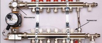
Comb device for heated floors
The temperature of the coolant supplied to the underfloor heating circuits should not exceed 50 °C, the optimal temperature schedule is 40/30 °C. If the floor surface heats up above 30 degrees, the room will become stuffy and uncomfortable.
Only gas boilers are capable of maintaining a supply of 40–50 °C, and even then with a loss of efficiency. To effectively consume gas or other energy carriers, water must be heated to 60 degrees, and then the temperature at the entrance to the transformer loops must be reduced. This is one of the main tasks of the collector block, consisting of the following elements:
- the collector itself – 2 separate tubes (supply and return) with wall mounting brackets;
- thermostatic pressure valves with connection for Eurocone pipes;
- flow meters (rotameters) with a scale of 0.5…5 l/min;
- end blocks with automatic air valves and drain valves;
- dial thermometer blocks;
- shut-off ball valves;
- bypass line with bypass valve.
Distributor design for underfloor heating systems
Rotameters and pressure valves are screwed into special sockets on the comb, the latter are closed with plastic caps. Air vents with drain valves are screwed into the ends of the collector tubes on one side, and blocks of thermometers and taps on the other. The bypass is installed depending on the design of the comb.
Note. Typically, flow meters are located on the supply line, thermal valves are on the “return” line. But there are also other models of collectors with rotameters on the return line. If you mix up the distributor tubes, you won’t be able to twist the valves instead of the flow meters - the internal shape of the bushings is different.
The thermometers are followed by ball valves, followed by a circulation pump and a mixing unit. Let's consider each element of the collector group separately.
Design and purpose of flow meters
Rotameters are designed to monitor and regulate the maximum fluid flow through loops. The elements are screwed into special pipes on the manifold without winding materials - the seal is an EPDM rubber gasket.
The flow meter body contains a spring-loaded rod with a working plate at one end and a control washer at the other. How does a rotameter work:
- The coolant flows through the side hole in the housing, then moves down, presses on the plate and goes into the pipe.
To adjust the maximum flow on the flow meter using the adjusting washer, you need to remove the protective plastic cap - The more water flows through the flow meter, the greater the pressure on the plate. The spring is compressed, the rod with the control washer is lowered. The flow rate in l/min can be observed on the scale marked on the transparent bulb of the element.
- The amount of flow is regulated by rotating the upper part of the housing. When twisting, the passage hole is partially or completely closed by the piston.
Reference. Some manufacturers' collectors are equipped with unregulated rotameters. To limit flow, separate valves built into the pipe body are used. See the video below to see how such elements look.
Flow meters installed on the return line are designed similarly, only the spring is on the other side of the control washer. The coolant enters from below and pushes the plate upward, the rod and washer rise. How to distinguish between different types of rotameters:
- if, in the absence of flow, the washer is at the top of the flask, then the flow meter is placed on the supply;
- if at zero water flow the washer is at the bottom of the scale, the element is intended for “return”;
- the scale on the flask is graduated in the appropriate direction, in the first case the counting is from top to bottom, in the second – from bottom to top.
During operation, rotameters must be maintained - cleaned when dirty. A transparent bulb serves as an indicator; when it becomes coated from the inside, the element should be unscrewed, disassembled and dirt removed from the working surfaces.
How does a thermostatic valve work?
Structurally, the product is no different from other similar thermal valves - radiator or two-way. When you press the spring-loaded rod, the plate lowers into the seat, blocking the passage of the coolant. It is possible to preset: the maximum flow rate is limited by rotating the valve core using a hex key.
Clarification. There are 2 types of valves - normally open and normally closed. The first ones are described above - when you press the rod, the passage closes. The latter are used less frequently, where the channel is initially closed, and when the rod is lowered, the hole opens.
The purpose of the thermostatic valve is to regulate coolant flow during operation (not balancing!). Management is implemented in 3 ways:
- Manual. The position of the rod is adjusted by a plastic handle, which is screwed onto the valve from above.
- Automatic RTL thermal heads that press the rod when the return flow temperature increases. Do not confuse them with conventional radiator heads that respond to air temperature.
- Electric servos connected to room thermostats or weather-dependent automation.
Manual control requires constant attention from the user - when the ambient temperature changes, you will have to press or release the rod. Thermal heads of the RTL type automate the process, but work well only on short loops - up to 60 m. Servo drives plus thermostats are applicable everywhere.
Other comb accessories
At the beginning of the publication, we listed the tasks that the underfloor heating collector group must solve. With balancing and flow control it is clear - these functions are performed by rotameters and valves. Let's move on to the remaining accessories:
- Terminal unit for emptying and automatically removing air bubbles. The element consists of a housing with a drain valve and a float air vent. The fitting is closed with a plug, which at the same time serves as a thumb for opening the valve.
- Blocks of dial thermometers marked up to 80–90 °C. The purpose is clear - measuring the temperature at the inlet and outlet of the comb.
- Ball shut-off valves. Depending on the method of connecting the collector to the heating, straight, angular, American and internal/external threaded taps are used.
- A bypass jumper with a bypass valve is used in systems with automatic control. If, due to warm weather, all circuits are closed, the coolant will flow through the bypass in a circle, the pump will not work on its own. In normal mode, the valve will not allow water to circulate directly and will force it to move in loops.
From left to right: drain end fitting with manual air valve, block with automatic air vent, ball valves and thermometers
Note. Through the terminal unit, you can not only drain the coolant, but also pump it in in case of repairs. The collector is cut off from the main line by taps, and the TP circuits are emptied or recharged through a side fitting.
The number and variety of additional fittings depends on the comb manufacturer. These accessories are the main ones; in addition to them, various plugs, adapters and valves are also used.
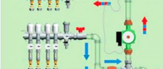
A mixing unit is located in front of the collector block; its composition depends on the method of preparing the coolant for the TP. There are 3 methods of bringing water in heated floors to the desired temperature:
- Mixing into hot water circuits with a two-way thermostatic valve. The element launches portions of the coolant at the command of a thermal head with an external temperature sensor in the form of a copper flask. The latter is attached to the metal wall of the manifold and connected to the head through a capillary tube.
- Mixing cooled and heated coolant using a three-way valve. The principle is as follows: the pump drives water through the bypass along the circuits; when it does not cool down, the valve opens the supply of heated water from the boiler line. The difference from the previous method is a smoother flow and mixing quality.
- Restriction of reverse flow by RTL thermal heads installed on the comb thermal valves. Here a pump module is not needed at all.
You can control a two- or three-way valve in three ways: manually, using a thermal head with a remote flask and an electric actuator. The latter is controlled by a controller that receives signals from room or weather sensors.
Feed and return manifold comb device
Combs are one of the main elements of the collector circuit; their main function is to distribute the coolant flow along the heating circuits. The element has a different design for lines of connected radiators and heated floors, the maximum number of involved circuits per collector does not exceed 12.
In relation to the diameters of the outlet fittings, the comb has a large cross-section (1.1 1/2 inches versus 3/4) and is connected to the main line through an end connection with elements of plumbing fittings. Typically, the pipeline is connected to the outlet fittings using compression fittings (Eurocones) - this method can be used to connect pipes made of cross-linked and heat-resistant polyethylene, metal-plastic, most often used in manifold heating systems. Combs are made of stainless steel, brass, plastic, some modifications are assembled from individual links.
Collector heating system - general principles for designing wiring diagrams
Correct design and calculations of the collector system can only be done by qualified specialists; when performing design work, they must be guided by the following rules:
- To determine the length of the circuits, parameters of heating radiators, coolant temperatures, it is necessary to calculate heat losses in the main line and circuits. This operation will allow you to determine the optimal dimensions of heating devices (the number of their sections) and the lengths of the contours of heated floors, otherwise the rooms will be too hot or cold during normal operation and additional adjustments will be required, reducing the efficiency and performance of the system.
- It is prohibited to connect heating radiators to collectors for heated floors - they have different hydraulic resistance and operating temperature conditions (coolant temperature 40 - 55º C for heated floors and 60 - 80º C for heating radiators).
- The permissible temperature difference between the water supply line and the return line is 5 – 15º C, the optimal difference is 10º C (55/45, 50/40, 45/35, 40/30 degrees).
- The temperature of the floor surface for living rooms and offices is 21 - 27º C, in living rooms, corridors, hallways - 29 - 30º C, in bathrooms and swimming pools - 33º C, in home workshops with active physical activity - about 17º C.
- The distance between adjacent turns of pipes in the living rooms of a private house lies in the range of 150 - 300 mm, it is excellent for different zones and changes in increments of 50 mm:
- For edge zones and near windows, the interpipe distance is 100 - 150 mm.
- In the central zone of medium and large rooms, the standard inter-turn distance is about 200 mm.
- In bathrooms, showers and bathrooms, a distance between hinges of 150 mm is used.
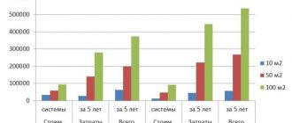
Rice. 8 Heat consumption of a cottage - calculation example
- The maximum loop length of large underfloor heating rings with a diameter of 3/4 inch (16 mm) should not exceed 70 - 90 meters, the value depends on the material of the pipes and increases with increasing diameter (for 20 mm pipes the permissible length is 120 meters.)
- The electric pump must have a rated power calculated mathematically; exceeding it leads to excessive noise, and a low value does not provide the optimal speed of coolant movement.
- According to building codes, the number of circuits connected to one comb should not exceed 8; the European standard allows the use of 12 branches.
- In underfloor heating manifolds, it is necessary to have mixing tees or bypass jumpers to ensure that the cooled coolant from the return line is mixed with the hot liquid entering the combs from the boiler. In the absence of such a device, the heated floor will overheat, causing discomfort among residents, increased wear or deformation of some types of pipelines.
Rice. 9 Design of a collector comb for heating radiators and its connection
What to consider when designing and installing
When carrying out planning and installation work, the following rules are followed:
- When pouring screed under heated floors, it is necessary to install damper gaps around the perimeter of the premises - this prevents deformation of the floor during thermal expansion of the screed and helps avoid the appearance of cracks.
- Also, the screed must have a thickness that ensures its uniform heating and heat retention for a certain time; usually the layer thickness is in the range of 30 - 50 mm. It should be taken into account that a thick layer will heat up for a long time and cool down slowly, while a thin layer, when heated quickly, retains heat for a short time - this will cause more frequent switching on and off of the equipment, and accordingly its increased wear.
- Under underfloor heating pipes, it is necessary to lay thermal insulation to prevent heat from escaping into the concrete slab; usually for these purposes, foil penofol (foamed polyethylene) is used, laid with an aluminum layer up to reflect thermal radiation.
- Before pouring the screed, coolant is supplied into the pipes with double pressure, which is released after it hardens - thus, the channels formed in the screed will not further compress the pipeline when it expands after filling with coolant.
- Supply pipes should not have butt joints under the screed; areas not related to the contours of radiators and heated floors should be placed in corrugated insulation to reduce heat loss.
- The floor covering of heated floors must have high thermal conductivity; the use of wood, linoleum, and carpets that interfere with heat transfer is excluded.
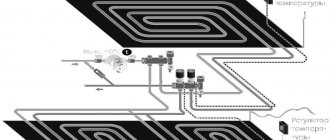
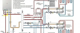
Rice. 10 Manifold wiring with hydraulic arrow - diagram
Principles of drawing up wiring diagrams
The optimal placement of the collector block is above the level of the heated floor; if it is heating a two-story dacha or cottage, it is more convenient to place it on the second floor in the center. In this case, all contours will have approximately the same length, in contrast to installing the block near external walls or in the corners of buildings.
System installation features
The collector heating system of a private house should be installed during the construction stage. After all, after laying or pouring the finished floor, installing such a system will become economically infeasible. The only solution to the problem in this case will be an open method of wiring installation.
Installation of distribution comb
On the floors of houses with horizontal heating distribution, to accommodate the collector, circulation pump and control equipment, you will need to install a closed box - a collector cabinet.
A closed box will protect equipment and shut-off valves from external mechanical influence and give the room a more aesthetic appearance
The manifold cabinet is installed in separate niches of rooms protected from moisture. Most often, a place is allocated for this in the hallway, dressing room or pantry.
When designing the heating of a two-story building, it will be necessary to install two collector groups: on the first and second levels. Additional distribution units will ensure approximately the same length of the circuit.
As an option, you can take as a basis a scheme in which the first group will be responsible for the distribution of heat along individual circuits, and the second will act as a key component in arranging a “warm” floor.
The heated coolant from the room with the boiler flows through the main lines to the collectors installed floor-by-floor
The number of collector inputs and outputs is always equal to the number of heating elements located on the floor: radiators or underfloor heating rings. For each room, a separate branch is laid, which, by combining several heating devices, will implement a passing or dead-end circuit.
To reduce the cost of connecting radiators, a “pass-through” circuit is used.
In a “pass-through” scheme, the thermal valve is installed only on the first circuit of the radiator; due to which the water flow is regulated on all devices connected in series behind it
With a “pass-through” system, several devices connected in series will be perceived as one element.
Pipeline laying options
When collecting pipes, the most commonly used method is laying pipes in a concrete screed. Its thickness varies between 50-80 mm, which is quite enough to “monolithize” the intra-house wiring of the heating system.
But according to SNiP, only unbreakable connections are allowed to be laid in concrete.
Any radiator or convector is connected to the collector through two pipes: “supply” and “return”, so the pipes are laid in the floor screed in pairs
For this purpose, metal-plastic pipes with a diameter of 16 mm are often used. Due to the fact that they bend easily, it is convenient to lay the pipeline under the floor.
When planning to fill metal-plastic pipes with concrete screed after pressure testing of the system, it is necessary to first wrap them with thermal insulation.
Such a layer will minimize the risk of pipe damage due to thermal expansion, since in this case they will “rub” not against the concrete, but against the insulation.
When laying pipes in a screed, connections in accordance with the requirements of SNiP must be left accessible, placing them above the floor level for this purpose
Plywood is laid on top of the screed, which is covered with a finishing floor covering: linoleum or parquet.
Pipes can also be connected to radiators from the side or from above, for example: in the space of a false ceiling.
Some craftsmen prefer to lay pipes externally, placing them along the walls and hiding them behind decorative skirting boards. But this method of installation entails an inevitable increase in the length of the pipeline.
It is not recommended to lay the pipeline through doorways. This can lead to the fact that when installing the threshold of an interior door, the pipe will be damaged at the time of drilling.
If the pipeline needs to be laid through a wall, in order to prevent its damage due to shrinkage of the building, the hole in the wall should be equipped with a sleeve.
A separate shut-off valve is installed on each hydraulic circuit coming from the distribution comb.
To be able to bleed the air accumulated in the system, install:
- on the distribution unit - air release valves;
- on radiators (accumulates at the highest points) - Mayevsky taps.
Installation and connection rules
It is best to select and install a collector at the stage of design and installation of the heating system.
Such intermediate structures are installed in rooms protected from excess humidity. Most often, space is allocated for these purposes in the hallway, pantry or dressing room.
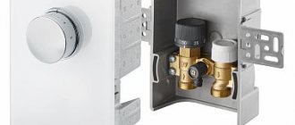
It is advisable to place the collector block in a metal cabinet specially designed for this purpose, equipped with holes in the side walls for pipe outlets
On sale there are overhead and built-in models of metal cabinets. Each model is equipped with a door and stampings on the sides.
In the absence of the opportunity to install a metal cabinet, it is easier to do it by fixing the device directly to the wall. The niche for arranging the collector block is placed at a low height relative to the floor.
There are essentially no generally accepted instructions for installing collector distribution circuits. But there are a number of main points regarding which experts have come to a common denominator:
- Availability of expansion tank. The volume of the structural element must be at least 10% of the total amount of water in the system.
- The presence of a circulation pump for each laid circuit. Regarding this element, not all experts are unanimous in their opinion. But still, if you plan to use several independent circuits, it is worth installing a separate unit for each of them.
An expansion tank is placed in front of the circulation pump on the return line. Thanks to this, it becomes less vulnerable to the turbulence of water flows that often occur in this place.
If a hydraulic arrow is used, the tank is mounted in front of the main pump, the main task of which is to ensure circulation in the small circuit.
The location of the circulation pump is not important. But, as practice shows, the service life of the device is somewhat higher on the “return” route.
The main thing during installation is to position the shaft strictly horizontally. If this condition is not met, the very first bubble of accumulated air will leave the unit without cooling and lubrication.
The process of assembling and connecting the collector system is clearly presented in the video block.
How to make a manifold for a heated floor with your own hands?
It is not difficult to assemble a collector for warm hydrofloors with your own hands. But you need to familiarize yourself in advance with how it works and make calculations.
COLLECTOR FOR WARM FLOOR - WITH YOUR OWN HANDS!!!
Calculation
Before you start calculating:
- Determine the number of branches of the floor system according to the prepared diagram.
- Find out how many heating devices will also be connected to this node.
- Determine the adjustment method and control process in the comb.
- Select the installation location of the device - it affects the design features and placement of pipes.
Afterwards, you can proceed to the calculation of all system parameters, such as: coolant temperature, water flow by all circuits, determining the location of sections.
In addition, in order for the device to effectively perform the task assigned to it and not interfere with the movement of liquid, the following rule must be observed - the distribution manifold must have a diameter with a cross-sectional area that is equal to or greater than S cross-sections of all pipeline pipes.
Let's consider an example: if you connect 4 pipes with a size of 20 mm to the comb, then the collector has a cross-section S = 4(πd²/4) = 4 (3.14 x 20 squared/4) = 1256 mm². That is, the pipe must have a diameter of at least 40 mm.
Selection of material
To assemble a homemade collector you will need:
- A comb is a piece of pipe that has holes with pipes inserted into them for connecting to the contours of a heated floor. The structure is sold ready-made, but you can weld it yourself from metal or polypropylene parts.
- Control valves - they are needed for each floor branch and are installed on the supply comb.
- Air vent - it is necessary to bleed air from the line.
- Brackets - necessary for mounting the device to the wall.
- Drain valve - the coolant will drain through it.
- Tees and connectors.
From these standard parts you can make your own manifold. In addition to the comb, the underfloor heating distribution unit includes: a three or two-way valve, a pump, and shut-off valves.
Assembly
Making a collector with your own hands is not a difficult task. When using polypropylene components, they must be soldered, maintaining tightness.
If the parts are steel, you will need skills in welding. In addition, the metal collector requires protection from corrosive influences; for this it needs to be coated with a primer or painted.
The process of making a polypropylene comb with your own hands:
- We weld the feed block - take a 32 mm polyurethane foam pipe and tees of the same diameter. The number of tees depends on the number of floor contours. First, measure the depth of the pipe entering the tee and put a mark. Using a soldering iron for polypropylene products, we solder a pipe with a tee.
- We measure from the tee along the pipeline the distance the pipe enters the tee, which we measured earlier. We cut the pipe along the marked line and clean the edges.
- Solder a coupling with a tap to the lower outlet of the tee.
- We repeat the above operations with the second tee. We weld the resulting part to the first workpiece. The number of such blanks depends on the number of underfloor heating circuits.
- We solder a tee to one edge of the resulting comb, on which we will place an air vent at one end, and a ball drain valve at the other.
- We screw on the ball valve and install the air vent.
- We use the same principle to make a return comb. Only instead of ball valves, we place control valves on the pipes.
- We fix the prepared combs (supply and return) on the mounting bracket.
All that remains is to fix this unit for the heated floor, connect it to the power source, and connect the circulation pump, it will ensure the movement of the coolant.
Rules for selecting distribution manifolds
Despite all the advantages of distribution manifolds, not every owner decides to install such equipment in his home. This is due to the design of the heating collector and the presence of some features relating to the acquisition and implementation of installation work.
In particular we are talking about the following:
- Quite a high price. The cost is mainly determined by the use of high-quality metals in the manufacture of the collector group for heating. In addition, there is a need to purchase various additional elements, fittings and equipment. However, it should be remembered that the technology is characterized by high quality and ease of use, as well as the ability to achieve maximum operating efficiency of heating devices.
- The need to use a circulation pump and other devices. The operation of a water collector for heating is possible provided that a pump is installed in the system, additional fittings for each heating device, various plugs and taps, as well as a properly selected collector cabinet.
- The complexity of installation work and its high cost. The equipment can only be installed by a qualified technician who understands the question of why a collector is needed in a heating system. This will necessarily require a certain amount of time and associated costs. Some systems can be installed and connected only at one stage of building a house, for example, a “warm floor” system.
Those who do not consider the listed factors to be particularly important can go shopping for a distribution manifold. However, the choice of equipment should be approached very carefully, paying attention to the material of manufacture and technical parameters of the system.
The following characteristics are of particular importance when choosing a heating collector assembly:
- System pressure. It is very important to establish at what values the equipment can function flawlessly.
- How much electrical energy will the collector consume?
- How many heating devices are planned to be connected to the distribution manifold?
- Device throughput.
- Possibility of adding circuits when increasing the number of heating devices.
- Availability of additional control and automation elements.
- Reputation of the manufacturer and reviews about it.
What types of distribution combs are there?
Manufacturers offer many models of collectors. Among them you can find devices with a maximum set of elements. The supply part is equipped with flow meters that regulate the coolant flow in each loop for a more even distribution. Thermal sensors are mounted on the return line to monitor the temperature of each heating device. The system allows you to automatically control the heating of each radiator. The cost of such a heating distribution comb is quite high.
Collector block with the maximum range of functional elements. The supply part is equipped with flow meters that regulate the flow and pressure of the coolant. Thermal sensors are installed on the return manifold
You can choose simpler options. For example, a brass element with an inch passage. The device has plugs on the return manifold, which allows you to install additional devices if necessary. There are cast parts and the simplest ones - with collet clamps for metal-plastic pipes. This is the cheapest and most problematic option. The device often “suffers” from possible leakage of coolant at the valve connection area, which is associated with rapid wear of the seal, which cannot always be replaced.
Craftsmen often make distribution combs on their own. Perhaps the best option of all is a stainless steel pipe of the required diameter, to which the outlets are welded. But, despite all its simplicity, it is quite an expensive pleasure. And not only because of the cost of the pipe. You will need to install a lot of additional elements to get full-fledged equipment. Therefore, many people use the most budget option - a heating manifold assembled from polypropylene tees, the required size of valves, etc.
The most accessible and inexpensive collector. Self-assembled from polypropylene tees, valves of the required size, pipes and other necessary parts