Designing a ventilation system for an industrial, public or residential facility consists of several successive stages, so you cannot jump to the next one without completing the previous one. Aerodynamic calculation of the ventilation system is an important component of the overall project; its purpose is to determine the acceptable cross-sectional dimensions of the ventilation ducts for its full functioning. Performed manually or using specialized programs. Only a professional designer can accurately carry out an important part of the project, taking into account the nuances of a specific building, the speed and direction of movement and the required air exchange rate.
General information
Aerodynamic calculation is a technique for determining the cross-sectional dimensions of air ducts to level out pressure losses, maintain the speed of movement and the design volume of pumped air.
With the natural ventilation method, the required pressure is given initially, but the cross-section must be determined. This is due to the action of gravitational forces, which encourage air masses to be drawn into the room from the ventilation shafts. With the mechanical method, a fan operates, and it is necessary to calculate the gas pressure, as well as the cross-sectional area of the box. Maximum speeds inside the ventilation duct are used.
To simplify the technique, air masses are taken as a liquid with zero percent compression. In practice, this is true, since in most systems the pressure is minimal. It is formed only from local resistance, when it collides with the walls of the air ducts, as well as at places where the area changes. This was confirmed by numerous experiments conducted according to the methodology described in GOST 12.3.018-79 “System of Occupational Safety Standards (OSSS). Ventilation systems. Methods of aerodynamic tests".
The technique involves selecting the area and cross-sectional shape for each section of the ventilation system. If we take it as a whole, then the definition of losses will be conditional, not corresponding to the real picture. In addition to the movement itself, the injection is also calculated.
Calculations of air ducts for ventilation, based on aerodynamics, are carried out with a varying number of known data. In one case, the calculation starts from scratch, and in the other, more than half of the initial parameters are already known.
Where to start?
Diagram of pressure loss for each meter of duct.
Very often you have to deal with fairly simple ventilation schemes, in which there is an air duct of the same diameter and there is no additional equipment. Such circuits are calculated quite simply, but what if the circuit is complex with many branches? According to the method for calculating pressure losses in air ducts, which is set out in many reference publications, it is necessary to determine the longest branch of the system or the branch with the greatest resistance. It is rarely possible to determine resistance by eye, so it is customary to carry out calculations based on the longest branch. After this, using the air flow rates indicated on the diagram, the entire branch is divided into sections according to this criterion. As a rule, costs change after branches (tees) and when dividing it is best to focus on them. There are other options, for example, supply or exhaust grilles built directly into the main air duct. If this is not shown in the diagram, but such a grid is available, you will need to calculate the flow rate after it. Areas are numbered starting from the one furthest from the fan.
Return to contents
Calculation order
The general formula for calculating pressure losses in air ducts for the entire ventilation system is as follows:
HB = ∑(Rl + Z), where:
- HB – pressure loss in the entire air duct system, kgf/m²;
- R – frictional resistance of 1 m of air duct of equivalent cross-section, kgf/m²;
- l – length of the section, m;
- Z – the amount of pressure lost by the air flow in local resistances (shaped elements and additional equipment).
Note: the value of the cross-sectional area of the air duct involved in the calculation is initially taken as for a circular duct shape. The frictional resistance for rectangular channels is determined by the cross-sectional area equivalent to a round one.
The calculation starts from the most distant section No. 1, then moves to the second section and so on. The calculation results for each section are added up, as indicated by the mathematical summation sign in the calculation formula. The parameter R depends on the diameter of the channel (d) and the dynamic pressure in it (P d), and the latter, in turn, depends on the speed of the air flow. The absolute wall roughness coefficient (λ) is traditionally accepted as for an air duct made of galvanized steel and is 0.1 mm:
R = (λ / d) R d.
It makes no sense to use this formula in the process of calculating pressure losses, since the values of R for various air velocities and diameters have already been calculated and are reference values (R.V. Shchekin, I.G. Staroverov - reference books). Therefore, it is simply necessary to find these values in accordance with the specific conditions for the movement of air masses and substitute them into the formula. Another indicator, dynamic pressure Р d, which is associated with the parameter R and is involved in the further calculation of local resistance, is also a reference value. Given this relationship between the two parameters, they are listed together in the reference tables.
The Z value of pressure loss in local resistances is calculated using the formula:
Z = ∑ξ R d.
The summation sign means that you need to add up the calculation results for each of the local resistances in a given area. In addition to the already known parameters, the formula contains the coefficient ξ. Its value is dimensionless and depends on the type of local resistance. Parameter values for many elements of ventilation systems have been calculated or determined experimentally, and therefore are found in reference literature. The local resistance coefficients of ventilation equipment are often indicated by the manufacturers themselves, having determined their values experimentally in production or in the laboratory.
Having calculated the length of section No. 1, the number and type of local resistances, you should correctly determine all the parameters and substitute them into the calculation formulas. Having received the result, move on to the second section and further, all the way to the fan. At the same time, we should not forget about the section of the air duct that is located behind the ventilation unit, because the fan pressure should be enough to overcome its resistance.
Having completed the calculations for the longest branch, the same ones are performed for the adjacent branch, then for the next one, and so on until the very end. Typically, all these branches have many common areas, so the calculations will go faster. The purpose of determining pressure losses on all branches is their overall coordination, because the fan must distribute its flow evenly throughout the entire system. That is, ideally, the pressure loss in one branch should differ from the other by no more than 10%. In simple terms, this means that the branch closest to the fan should have the highest resistance, and the one farthest should have the lowest. If this is not the case, it is recommended to return to recalculating the diameters of the air ducts and the speed of air movement in them.
echo get_the_author_meta("display_name", $auhor); ?>
The main requirement for all types of ventilation systems is to ensure optimal air exchange rates in rooms or specific work areas. Taking this parameter into account, the internal diameter of the air duct is designed and the fan power is selected. In order to guarantee the required efficiency of the ventilation system, the pressure loss in the air ducts is calculated; these data are taken into account when determining the technical characteristics of the fans. Recommended air flow rates are shown in Table No. 1.
Initial data
- The geometric characteristics of the air duct are known, and the gas pressure must be calculated. This is typical for systems where the ventilation method is based on the architectural features of the facility.
- The pressure is known, and it is necessary to determine the parameters of the air duct. This scheme is used in natural ventilation systems, where gravitational forces are responsible for everything.
- The pressure force and cross-sectional size are unknown. This is the most common situation, and most designers are faced with it.
Duct types
Air ducts are elements of the system responsible for transporting exhaust and fresh air. The composition includes main pipes of variable cross-section, bends and half-bends, as well as various adapters. They differ in material and cross-sectional shape.
The scope of application and the specifics of air movement depend on the type of air duct. There is the following classification by material:
- Steel - rigid air ducts with thick walls.
- Aluminum - flexible, with thin walls.
- Plastic.
- Fabric.
According to the shape of the sections, they are divided into round of different diameters, square and rectangular.
Features of aerodynamic calculations
Axonometry
Calculation of aerodynamics is performed strictly when the required volumes of air masses are calculated. This is the basic rule. The installation points of air ducts and deflectors are also determined in advance.
The graphical part for calculating aerodynamics is an axonometric diagram. It indicates all devices and the length of sections. Then the overall network is divided into segments with similar characteristics. Each section of the network is calculated separately for aerodynamic resistance. After determining the parameters in all areas, they are transferred to the axonometric diagram. When all the data is entered, the main air duct line is calculated.
Algorithm for calculating air pressure losses
The calculation must begin with drawing up a diagram of the ventilation system with the obligatory indication of the spatial location of the air ducts, the length of each section, ventilation grilles, additional equipment for air purification, technical fittings and fans. Losses are determined first for each individual line and then summed up. For a separate technological section, losses are determined using the formula P = L×R+Z, where P is the loss of air pressure in the design section, R is the loss per linear meter of the section, L is the total length of the air ducts in the section, Z is the loss in the additional fittings of the system ventilation.
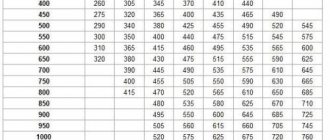
To calculate pressure loss in a round duct, the formula Ptr is used. = (L/d×X) × (Y×V)/2g. X is the tabulated coefficient of air friction, depends on the material of the air duct, L is the length of the design section, d is the diameter of the air duct, V is the required air flow speed, Y is the air density taking into account temperature, g is the acceleration of fall (free). If the ventilation system has square air ducts, then table No. 2 should be used to convert round values to square ones.
Table No. 2. Equivalent diameters of round air ducts for square ones
| 150 | 200 | 250 | 300 | 350 | 400 | 450 | 500 | |
| 250 | 210 | 245 | 275 | |||||
| 300 | 230 | 265 | 300 | 330 | ||||
| 350 | 245 | 285 | 325 | 355 | 380 | |||
| 400 | 260 | 305 | 345 | 370 | 410 | 440 | ||
| 450 | 275 | 320 | 365 | 400 | 435 | 465 | 490 | |
| 500 | 290 | 340 | 380 | 425 | 455 | 490 | 520 | 545 |
| 550 | 300 | 350 | 400 | 440 | 475 | 515 | 545 | 575 |
| 600 | 310 | 365 | 415 | 460 | 495 | 535 | 565 | 600 |
| 650 | 320 | 380 | 430 | 475 | 515 | 555 | 590 | 625 |
| 700 | 390 | 445 | 490 | 535 | 575 | 610 | 645 | |
| 750 | 400 | 455 | 505 | 550 | 590 | 630 | 665 | |
| 800 | 415 | 470 | 520 | 565 | 610 | 650 | 685 | |
| 850 | 480 | 535 | 580 | 625 | 670 | 710 | ||
| 900 | 495 | 550 | 600 | 645 | 685 | 725 | ||
| 950 | 505 | 560 | 615 | 660 | 705 | 745 | ||
| 1000 | 520 | 575 | 625 | 675 | 720 | 760 | ||
| 1200 | 620 | 680 | 730 | 780 | 830 | |||
| 1400 | 725 | 780 | 835 | 880 | ||||
| 1600 | 830 | 885 | 940 | |||||
| 1800 | 870 | 935 | 990 |
The horizontal axis indicates the height of the square duct, and the vertical axis indicates the width. The equivalent value of the circular section is found at the intersection of the lines.
Air pressure losses in bends are taken from table No. 3.
Table No. 3. Pressure loss at bends
To determine pressure losses in diffusers, data from table No. 4 is used.
Table No. 4. Pressure loss in diffusers
Table No. 5 gives a general diagram of losses in a straight section.
Table No. 5. Diagram of air pressure loss in straight air ducts
All individual losses in a given section of the air duct are summed up and adjusted with table No. 6. Table. No. 6. Calculation of flow pressure reduction in ventilation systems
During design and calculations, existing regulations recommend that the difference in pressure loss between individual sections should not exceed 10%. The fan must be installed in the area of the ventilation system with the highest resistance; the most distant air ducts must have minimal resistance. If these conditions are not met, then it is necessary to change the layout of air ducts and additional equipment, taking into account the requirements of the regulations.
Calculation method
The most common option is when both parameters - pressure force and cross-sectional area - are unknown. In this case, each of them is determined separately, using its own formulas.
Speed
It is necessary to obtain dynamic pressure parameters in the designed area. It must be remembered that the air flow is known in advance, and not for the entire system, but for each section. Measured in m/s.
υ fak = L/(3600×Ff), where
L – air flow in the area under study, m3/h
Pressure
The ventilation system is divided into separate branches (sections) according to places where air flow changes or changes in cross-sectional area. Each one is numbered. Natural available pressure is determined by the formula:
Δre = h .g ( ρн –ρвн), where
h – difference in rise between the upper and lower points ρн and ρвн – density inside/outside
Densities are determined using the parameters of the temperature difference between the air inside and outside the room. They are specified in SNiP 41-01-2003 “Heating, ventilation and air conditioning”. Next comes the formula:
Σ(R . L .βш +Z) ≤Δ re, where
Σ(R . L .βш +Z) – the sum of the pressure flow in the area under consideration, where
R – specific friction losses (Pa/m); L – length of the section under consideration (m); βш – coefficient of roughness of the walls of ventilation ducts; Z – pressure loss in local resistances; Δpe – natural available pressure.
The selection ends when the cross-sectional size of the air channel satisfies the conditions of the formula. Possible size options are presented in the tables:
It is important to provide a small margin of pressure; 5-10% will be sufficient.
The selection of the air duct is carried out according to special tables. If a square or rectangular cross-section is required, then it is given according to the formula for the equivalent of a round channel:
deq = 2a. in /(a+b), where
a,c – geometric dimensions of the channel, cm
Aerodynamic calculation of the ventilation system
Ventilation services › Ventilation design ›
What is aerodynamic calculation and why is it needed? We will try to convey to you the importance of carrying out competent aerodynamic calculations in simple and accessible language using the example of a ventilation system, although everything that will be said here will equally apply to heating and air conditioning systems.
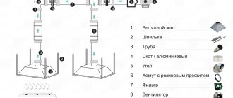
The ventilation system, as you already understand, consists of many elements. Some of them:
- protective outer grille;
- check valve;
- filter;
- air heater;
- fan;
- noise suppressor;
- air duct network;
- supply and exhaust grilles.
Tasks of the ventilation system equipment:
- take fresh air from the street;
- clear the air of dust and fluff;
- heat the air (in winter);
- lower the sound pressure level;
- distribute the prepared air throughout the rooms;
- distribute prepared fresh air evenly throughout each room;
- collect exhaust air from each room;
- collect exhaust air from all rooms;
- remove exhaust air to the street.
Main parameters characterizing the Ventilation System:
1. Working fluid.
In this system it is air. In the list above, the word air was used 8 out of 9 times. Any working fluid, be it air, or water, or freon, or any other, is characterized by such basic (from the point of view of aerodynamic calculation) physical quantities as:
- density;
- dynamic viscosity;
- kinematic viscosity.
Moreover, the values of these quantities depend on the temperature of the working fluid.
As you can see from the tasks of the Ventilation System equipment, in order to pick up, prepare, deliver, distribute, collect and remove air, it must be passed through a number of equipment. The same amount of air passing through holes with different cross-sectional areas will, accordingly, have different speeds. From here we formulate a second very important parameter.
2. Speed of movement of the working fluid.
When moving, the air “collides” with various elements of the ventilation system, which impede the movement of air. These elements are called:
3. Local resistance, which are characterized by the corresponding coefficient of local resistance, and the amount of obstacle to air movement is called:
4. Loss of pressure.
Now let’s summarize all the main parameters necessary for carrying out an aerodynamic calculation:
r is the density of the working fluid.
v is the speed of movement of the working fluid.
x is the local resistance coefficient.
DP - pressure loss.
All these parameters are “connected” by the following formula:
DP=x*r*v2/2
Now we can formulate the task of carrying out an aerodynamic calculation - to determine the total value of pressure loss on all elements of the Ventilation System (in this example). Having the value of the total pressure loss, we finally have the right to select a fan (Heating systems - pump, Air conditioning systems - compressor).
Absolutely any fan has a “pressure-flow” characteristic. The greater the pressure loss in the Ventilation System network, the lower the fan air consumption, up to the complete cessation of air supply. And vice versa, the lower the pressure loss in the Ventilation System network (down to zero), the greater the fan air consumption.
Now we will draw your attention to a very interesting point. The values and characteristics of the available pressure vary greatly. How can this be? Absolutely the same fan from different sellers has different performance. If you can answer this question yourself, then our article was not written in vain and you did not waste your time. That's right... "zero" pressure loss. In this particular example, the fan capacity is 1260 m3/h with a network pressure loss of 0 Pa.
As you understand, this is practically impossible. Any ventilation network creates a certain resistance to air movement. Therefore, you will never get a capacity of 1260 m3/hour from the fan.
But as you now already know, to determine the real performance of this fan, it is necessary to carry out an aerodynamic calculation of the Ventilation System.
In conclusion, I would like to say a few words about local resistance. For example, let’s take a heating system element such as a tee. Many people believe that the coefficient of local resistance of a tee is a constant value, absolutely not taking into account the direction of movement of the water flow (either directly or along the outlet to the side), they do not take into account whether the water flow is divided or, conversely, the flows are combined. Also, the percentage ratio of separating/connecting flows relative to the total water flow is not taken into account. And if we take into account all the aspects described above, then the value of the local resistance coefficient of a given tee, even to a first approximation, can vary in the following range 0.9...90. As you can see, the possible error is two orders of magnitude. How many elements does the heating system consist of? These are hundreds, thousands of elements. And what then could be the magnitude of the error?... The result is an incorrectly selected pump, which will either never produce the required parameters or will very soon fail. This once again confirms the need for an aerodynamic calculation.
INTECH is an engineering company. On our resource air-ventilation.ru you can find out the necessary information and receive a commercial offer.
Receive a commercial offer by email:
Need some advice? Call:
+7(495) 146-67-66
Reviews about :
The information posted on the site is for informational purposes only and under no circumstances constitutes a public offer.
Possible errors and consequences
The cross-section of the air ducts is selected according to tables where standardized dimensions are indicated, depending on the dynamic pressure and speed of movement. Often, inexperienced designers round down the speed/pressure parameters, which results in a smaller cross-section change. This can lead to excessive noise or the inability to pass the required volume of air per unit of time.
Errors are also allowed in determining the length of the air duct section. This leads to possible inaccuracy in the selection of equipment, as well as an error in calculating the gas velocity.
Sample Project
The aerodynamic part, like the entire project, requires a professional approach and careful attention to the details of a particular object.
carries out qualified selection of ventilation systems in accordance with current standards, with full technical support. We provide services in Moscow and the region, as well as neighboring regions. For detailed information, please contact our consultants; all methods of contacting them are listed on the “Contacts” page.