- Waste oil burner based on the Babington principle
- Types of Russian-made waste oil burners
- The design of a finished burner operating on waste oil
- Filtration as the start of burner operation during production
- Warming up used oil before burning it
- Compressed air supply for waste oil recycling
- What is Babington's famous invention?
- Do-it-yourself burner: operating principle
- How to build your own apparatus based on the Babington burner principle: drawings
- Advantages and disadvantages of the Babington burner
- How to make a burner with your own hands according to diagrams and drawings
- Video: DIY oil burner
Waste oil burner based on the Babington principle
Many craftsmen in their practice are faced with the need for new devices, such as a waste oil burner. For owners of auto repair shops and garages, this will replace the furnace for heating the premises, especially if there are decent reserves of used oil and other fuel. Burners, if you understand the principle of their operation, can also be adapted for mixed fuel.
Using a waste oil burner, you can heat technical rooms.
Features of furnaces using waste oil, their advantages and disadvantages
The exhaust furnace is a compact, economical unit
Stoves that use used engine oil as fuel are practically no different from other potbelly stoves in terms of simplicity of design and unpretentiousness in manufacturing materials. As for the method of burning fuel, the processes that occur are associated with the characteristics of the fuel used.
First of all, it should be noted that modern engine oil is a multicomponent substance with a high content of chemical compounds. During use, the lubricating fluid is additionally saturated with decay products of automobile fuel, as a result of which it becomes extremely hazardous to the environment.
Simply burning waste in an open flame is ineffective and unacceptable - it burns poorly, forming acrid smoke, which, in addition to soot, also contains various carcinogenic compounds. A completely different situation occurs with volatile hydrocarbons, into which automobile oil heated to a high temperature breaks down.
Gaseous substances are highly flammable and, when burned, release large amounts of thermal energy.
You can borrow work from friends or buy it at a car service center.
Depending on the method of supplying waste oil to the combustion zone, potbelly stoves are divided into several types:
- with pyrolysis combustion;
- using supercharging and fuel atomization;
- with drip feed.
A potbelly stove should not be perceived as a stove intended exclusively for installation in small technical and utility rooms. Using heating devices equipped with an air collector or a water jacket, it is possible to build complete heating systems for residential buildings.
Scheme of a furnace with drip feed of waste oil
A wide range of homemade liquid fuel stoves, which begins with simple mobile stoves and ends with stationary heat generators, determines their use both in the home and in industry. Today, equipment operating on waste lubricants is heated by:
- residential buildings;
- auto repair shops and garages;
- small production workshops;
- workshops;
- warehouses;
- vegetable stores and greenhouses.
Of course, the ideal option is to install liquid heat generators in auto repair shops. This will not only allow you to heat the premises for free, but also additionally save money on the disposal of drained oil. Nevertheless, such a potbelly stove will also be useful in a small private garage - the cost of working out is much cheaper than other types of fuel.
Like any other homemade heat generator, a waste furnace has its advantages and disadvantages. The advantages of these designs include:
- low cost of fuel. You can drain the waste from your own car, take it from friends, or literally buy it for next to nothing at car service stations;
- high heat transfer, which promotes rapid heating of the room immediately after ignition;
- Efficiency up to 90%;
- autonomy;
- work for a long time when installing large fuel tanks;
- undemanding to manufacturing materials;
- possibility of equipping with a water circuit or an air heat exchanger;
- ease of operation;
- recycling of fuel without the risk of environmental pollution.
If we talk about the disadvantages of units operating during mining, they are inherent in all potbelly stoves. Firstly, this is the low heat capacity of the structure. The temperature in the room will begin to drop immediately after the flame goes out. Secondly, you will need to install a long chimney, which means that you will need to clean it much more often. Thirdly, the hot walls of the diffuser and heat exchanger do not allow installing the device directly in the house - a special extension will be required. It should also be noted that the use of liquid fuel increases the requirements for operational safety - you will need to be extremely careful and attentive.
Types of Russian-made waste oil burners
During the cold season, not only residential but also auxiliary premises need heating. Currently, devices using different types of fuel are used for heating, including waste or waste technical oil. On the Russian market you can find devices that process different fuel bases, as well as having a narrow specialization. Based on the type of fuel burned, such devices are:
In terms of functionality, burners used for testing are not only heating, but also welding and lighting.
- gas;
- liquid fuel;
- combined.
The simplest and most economical device for heating a room is considered to be an exhaust burner. According to functionality, burners are divided into 3 subtypes:
- welding;
- lighting;
- heating.
The operating principle of these devices was borrowed from primitive kerosene gas back in the 50s. Quite quickly, the simplest burners became popular; they began to be purchased for heating country houses and garages. In those days, any fuel was inexpensive, but over time, zealous owners, inventors and innovators began to look for a replacement for gasoline, diesel fuel and kerosene. Fuel oil and waste oil were used, which are now used as full-fledged fuel. Today, the device is still relevant, and is also an excellent way to preserve the environment.
Note! In a room where any liquid fuel device will be used, be it a homemade gasoline burner, a working unit, or a DIY diesel fuel burner, there must be a fire extinguisher!
The types of burners used for processing are liquid fuel, gas and combined.
Operating principle and types of structures
Since any oil contains flammable substances, they can be burned. People have long been trying to make the most of this for their own benefit, but solving this problem is not so easy, especially if they try to burn used oil, which contains many additional components. There are three types of devices for this purpose:
- Ejection. Very effective system. Excellent fuel combustion, high temperature, low emissions, but it is almost impossible to do at home. In addition, not all fuels can be used without pre-treatment.
- Evaporative. The easiest to assemble from scrap material, but its effectiveness is low, there is a lot of waste and pollution. Additional equipment is required for ignition and smooth operation.
- Injection. The most acceptable option for making an oil burner with your own hands. Relatively simple design, easy to maintain, unpretentious to fuel. The main disadvantage is the inability to use in residential premises.
In this video you will learn how the burner works during mining:
Some craftsmen try to adapt blowtorches for heating by working off, but most often such endeavors result in complex alterations and a complete abandonment of the original burner design. The Babington oil burner has become most popular in recent years.
Robert Babington patented his invention at the end of the last century using one of Murphy's laws - to do everything in reverse. Robert did not spray the fuel by blowing it out of the nozzle, but simply tried to force air through the oil film . It produces an oily aerosol that burns beautifully. It’s not for nothing that they say that everything ingenious is simple.
A novice master can make such a burner if he has a garage or workshop with a bench vice and an electric drill. Having collected the necessary materials and prepared the tools, they make drawings of a waste oil burner or find ready-made ones on the Internet.
The design of a finished burner operating on waste oil
When purchasing gas burners and similar equipment, people are often interested in one or another element and its purpose in the overall design. For example, they want to know where the oil should flow from and where, how it ignites, and so on. When they think about how to make a burner at home, looking for a model for building a homemade analogue, even more questions arise. Most often people are interested in replacing injectors and oil containers with something suitable from available means.
Having at their disposal photos, diagrams and drawings of a waste oil burner, not every master will immediately get down to business. The main reason is the large number of specific details.
On a note! It doesn’t matter what the device is made of, the principle of operation of all burners is approximately the same: filtered and heated oil is supplied from the main container and burned in the combustion chamber.
The multicomponent process consists of several stages, and the success of its operation will depend on the quality of the components of the drip burner using waste oil with your own hands:
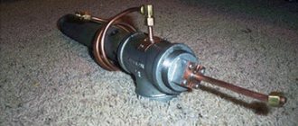
The operating principle of a burner operating on waste oil.
- extraction and filtration of waste;
- pumping and heating of purified oil;
- combustion process to produce heat.
Burner assembly
Now let's talk about how to make a working burner and start it up. In fact, after the injector has been manufactured, we can safely say that the main part has been manufactured and only assembly is expected. Now you need to combine everything in the body. And as it you can use a tee and a metal pipe screwed to it. Its length should be approximately 20-40 cm. The nozzle should be welded or screwed to the tube that supplies air. The second end of the tube is connected to the compressor.
The sprayer is placed inside the tee and secured with fittings. You need to make a hole in the tee itself; a tube for supplying used oil is placed in it. It is necessary that it ends above the sprayer. The lower element of the tee is used as the outlet tube. An adapter for a thin tube is screwed in here, through which the excess will flow into the drain tank. To organize the supply and removal of oil, you need to use flexible thin copper tubes.
Read also: Do-it-yourself metal detector, detailed instructions with diagrams
Filtration as the start of burner operation during production
Enterprises that produce finished devices operating on liquid fuel or waste are equipped with additional options that purify the oil. These are the so-called intake floats, which take the purest portion of the substance from the surface for heating. This principle of waste collection is currently inherent in the vast majority of manufactured products belonging to this category.
Next, through a hose made of material resistant to aggressive environments, used oil is supplied in portions. The tube is usually immersed approximately to the middle of the main container, so the solid suspension remains at the bottom, and a cleaner layer is used for heating and processing. At this stage, it is possible to filter the fuel quite efficiently without additional effort. Dirty impurities, sand and other insoluble components remain at the bottom.
Note! The duration of operation of a do-it-yourself waste oil burner nozzle largely depends on the purity of the fuel. Therefore, it is worth taking care of at least a rough cleaning of the oil fraction supplied to the firebox.
In order for the burner to operate for a long time, care must be taken to clean the fuel.
As you know, filters can be single-use or reusable. Sifting of coarse particles can be done through several layers or filter elements, like the ready-made heating pads from Smart Burner. The traditional equipment of different products is approximately the same: ready-made devices are rarely produced without a filter or elements replacing it.
A small transfer pump is a standard design part responsible for the uninterrupted flow of oil. If you organize the supply for a stationary unit according to the principle of communicating vessels, then in a homemade burner it can flow to the nozzle by gravity.
Do-it-yourself stove from a gas cylinder
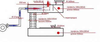
Looking at the drawing of a homemade furnace during testing, we can notice that the role of the body is played by the cylinder itself, from which the upper part is sawed off. Case height – 550 mm.
Now we will figure out how to assemble an exhaust furnace from a gas cylinder. For this we will need a welding machine, power tools and a tape measure. In addition to the cylinder, you need to prepare:
- A piece of pipe with a diameter of 110 mm (air will be supplied through it);
- A piece of pipe with a diameter of 20 mm (fuel will be supplied through it);
- Metal for welding legs;
- Metal for making a bowl.
From the upper part we make a lid through which a pipe with a diameter of 110 mm will be inserted into the cylinder, not reaching the bottom by 60 mm. We weld a cover with four holes to the bottom of this pipe (one hole in the center, its diameter is 22 mm, three more holes with a diameter of 5 mm along the radius, with a slight indentation from the middle). A pipe with a diameter of 20 mm is inserted into the hole in the middle, through which fuel is supplied.
We weld a metal bowl to the bottom of the inner pipe - diesel fuel will burn in it, heating the bowl, into which the waste will subsequently drip. The cup itself is made from a piece of pipe with a diameter of 140 mm and a piece of sheet iron, cut in the shape of a circle and welded on the bottom side. The height of the bowl is 20 mm.
Read also: DIY knife handles photo
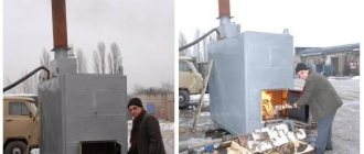
Ultimately you should end up with a design similar to this.
Next, we proceed to forming the chimney and vent. The ash pan is made at the very bottom of our stove - through it diesel fuel is poured into the bowl for ignition and heating. Also, dripping waste is ignited through it. We cut a hole for the chimney in the upper side part - weld a piece of pipe with a diameter of 110 mm into the resulting hole. Subsequently, the chimney pipe itself will need to be welded to it.
To complete everything, we weld the top cover - the process of creating a waste oil furnace with your own hands can be considered complete. Now it needs to be tested in test mode - it is best to conduct experiments on the street. Pour some diesel fuel into a cup and wait until it burns out. After this, we open the exhaust valve and watch how the process of reaching the operating mode begins. Only after completing the test can you begin installing the stove in a heated room.
Warming up used oil before burning it
An equally important stage in preparing the device for operation is heating the used oil before complete combustion to release heat. When heated, the oil becomes more liquid and plastic, resulting in an optimal consistency that burns well.
A preheating tank or heating coil is needed for any do-it-yourself waste oil burner - the drawings show an intermediate location. Usually this is a separate chamber or capsule of small volume, hidden in the middle of the body. The purpose is to warm up the fuel as efficiently as possible before the combustion process. Finished products most often have a temperature relay that monitors the heating level. As a rule, they operate in an operating range of 0-150 °C.
Some burner models are equipped with an electric heating element for heating the oil.
Note! Burners adapted for combined suspensions usually have a container for heating. Diesel fuel in homemade diesel burners does not require heating.
Manufacturers decide differently how to organize this stage. The Gnome waste oil burner (and other similar models) has a small electric heating element inside the container, which is responsible for heating the waste oil to the required level. Just as in this case, each manufacturer decides in its own way the issue of oil supply. Often float switches and pumps are responsible for the level of its supply. The system switches off automatically when the preheating tank is full.
Burner operation
The article shows a simplified diagram of the burner, which allows you to understand the principle of its operation. After spraying, the mixture is ignited, and the flame is used for some purpose. You can install this burner in a boiler running on any type of fuel. In principle, no one is stopping you from making a boiler yourself. Please note that there is practically no evaporation during operation - all processes take place at low temperatures, the main role is played by compressed air.
Read also: Pattern on the handle of an ax
To make combustion more efficient, you can make a heating system, just use a low-power heating element in it. In this case, efficiency will increase, heat transfer will improve, and the flame will have a beautiful and even flame.
Compressed air supply for waste oil recycling
Compressed air is required to prepare the oil mixture for combustion by atomizing it. This transport is directed to the nozzle, which is carried out under pressure. Due to the supply of oxygen through a separate channel, it ensures the combustion process in any device, including a DIY Babington burner using waste oil. Although the device was initially patented as running on diesel fuel, it was also adapted to run on technical oil.
Successful air supply requires a mini-compressor built into ready-made liquid fuel devices. It can be transported in other ways, for example, using the pneumatic principle. If there is no compressed air, the nozzle may not work correctly.
Compressed air in the burner is necessary to prepare the oil for combustion.
On a note! A small pressure gauge helps monitor the operating pressure, thereby maintaining the parameters necessary for full operation of the entire device.
Air flow regulation is provided by a special solenoid valve on the housing. Expensive equipment also includes air filters to purify the air. They will be useful in dusty mini-workshops, boiler rooms or other rooms where the air taken for the combustion process has many impurities. To operate a burner nozzle using waste oil yourself, you need an adjustable secondary air supply. The following burner parts are responsible for the synchronous operation of all components:
- nozzle (nozzle);
- fuel compartment;
- heating tank;
- air supply valve;
- oil supply regulator;
- a pressure gauge for checking pressure (there may not be one);
- blower (fan).
In finished devices, ignition is provided by electrodes. Compressed air is supplied through the air channel, from where it enters the nozzle. After heating, the used oil also goes there. If the nozzle is clean, it produces high-quality ignition of the fuel, which implies the appearance of an even, continuous flame.
Each exhaust burner must be equipped with an air supply valve.
Factory furnaces, their characteristics and features
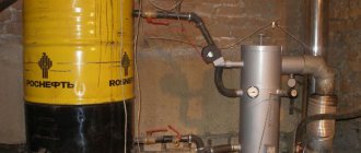
The photo shows the factory furnace Teplamos NT-612, running on waste oil.
Before we tell you how to make a furnace for working with your own hands, we will look at several models of factory-assembled furnaces. A typical example is the Teplamos NT-612 oven. This is a typical drip fanless heater, intended for use in garages, workshops, hangars and other non-residential and technical premises. The power of the device varies from 5 to 15 kW, fuel consumption - from 0.5 to 1.5 l/hour.
Teplamos NT-612 is a closed type oven. It contains a chimney and a pipe for air supply. Combustion of fuel occurs in the inner chamber. In order for the stove to reach operating mode, it must be heated with a small amount of diesel fuel poured into a special bowl . After the fuel burns, we get a stove ready for refueling and further work - we open the waste supply and set it on fire.
A mini-furnace of the “potbelly stove” type is as simple as a matchbox. It is made of sheet iron and is characterized by versatility - it heats non-residential premises and allows you to cook food (small pots, pans and kettles are placed on the surface of the afterburning chamber). The power of such units varies widely. The equipment operates on the basis of pyrolysis.
Zhar MS-25 can operate on both waste oil and diesel fuel.
Let's consider a more solid stove - this is the heat generator Zhar MS-25. The unit can operate on both waste oil and diesel fuel. For its operation, electricity is required to power the built-in fan. The thermal power of the device is 25-50 kW, which allows it to heat an area of up to 500 square meters. m. In this case, the maximum flow rate is up to 4.5 l/hour. The stove is quite large, it weighs 130 kg and requires a good chimney. The temperature of the air entering the heated rooms is +50-70 degrees.
What is Babington's famous invention?
Every invention has its own author, even if his name is undeservedly forgotten by his descendants. For example, in 1969, British inventor Robert Babington received a patent for a stove running on diesel fuel, which was reminiscent of lighting kerosene gas operating on kerosene vapor. Robert Babington's design was originally designed for kerosene, then it was adapted for diesel fuel. When the number of cars increased disproportionately, the used oil had to be disposed of somehow. Therefore, innovators were looking for devices suitable for these purposes.
First, based on the patented invention of R. Babington, a do-it-yourself diesel burner appeared, then it was adapted for burning oil and other types of fuel. The testing device appeared much later than the diesel design, but it surpassed its predecessor in popularity and safety.
After some time, a similar device was proposed again, since the first patent had expired, and the liquid fuel stove had not lost its relevance. Similar devices were repeated in different versions, and not only self-taught craftsmen, but also design bureaus of reputable enterprises tried to assemble the Babington burner with their own hands.
By design, the burner is a simple device, so it can be successfully manufactured at home. It is characterized by fairly high efficiency in terms of obtaining the heat necessary for heating:
Burner diagram based on the Babington principle, where 1 – heating sensor; 2 – casing; 3 – heat exchanger; 4 – fuel sprayer; 5 – glow plug; 6 – supercharger; 7 – fuel pump; 8 – friction clutch; 9 – electric motor; 10 – lever for switching operating modes; 11 – fan; 12 – skeleton; 13 – fuel pipe; 14 – combustion chamber.
- technological installations;
- small workshops;
- workshops;
- garages;
- warehouse and utility rooms.
On a note! You should not adapt a homemade burner with your own hands for heating your home, since burnt oil has a specific smell.
Furnace add-ons
When making a drip-type furnace with your own hands, you must remember that it can be supplemented with some elements. This will allow the structure to be used for heating several rooms at once. The stove will have this functionality if it is connected to the heating system. Initially, you need to install a tank for heating water, which must be connected to the system, only after that the return line is connected. Thus, the installation will not only be able to heat rooms, but will also allow heating water and cooking food. A design of this type has many advantages, one of which is its small dimensions, which allow the stove to be dismantled in a short time and then installed in another place. You will definitely need to equip homemade drip-type furnaces with your own hands with a chimney, the height of which should not be less than 4 m. Make sure that the chimney is devoid of horizontal sections. In order to be able to clean the pipe, which will have to be done once a week, you need to equip the element with a system that will allow dismantling.
Read also: Do-it-yourself pipe bender for a profile pipe photo
Do-it-yourself burner: operating principle
If you look at photos, pictures and drawings, it becomes obvious that the secondary oil forms a thin film on a curved surface. Through a groove, gas or air is supplied into the container under low pressure. After heating, the oil is atomized by this air flow, ensuring high-quality ignition.
It was this method of ignition that became the basis for inventions that have become widespread in homemade devices and drip burners using waste oil, produced in factories. Used oil is essentially free fuel, a used suspension. Therefore, it is considered more advantageous compared to other heat sources:
You can make a waste oil burner yourself.
- solid fuel and briquettes for a homemade pellet burner;
- gasoline and diesel fuel;
- electricity;
- natural gas;
- kerosene;
- fuel oil.
On a note! Although waste remains the cheapest basis for releasing heat during disposal through combustion, it is still recommended to prepare oil clogged with impurities - to allow the water to settle and filter it from heavy suspended matter.
The first devices using kerosene, diesel fuel and oil smoked heavily and emitted an unpleasant odor. Later they offered a do-it-yourself gasoline burner and devices using other combustible raw materials, but an active search was underway for budget fuel. Oil turned out to be a suitable source of heat, but the soot and smell negated all the benefits. Therefore, all the efforts of the inventors went into eliminating these disadvantages of the burner for waste oil boilers. This should have been facilitated by complete combustion, heating and filtration of contaminated fuel.
Features of making your own liquid fuel burner
Babington burner
Its internal size is one inch and the wall is quite thick. The lower section is necessary to supply an oil-air suspension to the compartment where combustion occurs. The upper section is used as a burner bell. A torch of flame with a high temperature emerges from it. To ensure the flow of air that is pumped into the furnace to form a torch, use a simple household vacuum cleaner with high power.
Making a burner with your own hands is quite simple. To do this, you will need a welding machine, which is used to connect the parts, as well as a grinder and a lathe.
Manufacturing begins with the body. To do this, you need to find an empty gas cylinder of a suitable size. Then remove the filler hole and use a template to mark the pipe fasteners. Then use an electric drill to drill them along the inside of the circuit. To do this, you need to use a drill in the form of a spiral. With a high degree of accuracy, using a chisel or grinder, you need to remove the jumpers between the holes. To ensure that the holes for fitting the pipes are of the correct shape, it is necessary to bore them manually using a round file. This can also be done with a cutter by placing it in an electric drill. When working with metal, you must follow safety regulations.
Pipes are inserted into the holes of the required size and welded. The pipes are measured in advance and sawed off with a grinder. A hole is made in the lower half of the pipe and an M16 nut is welded. This hole is necessary for attaching the oil nozzle.
The principle of feeding waste into the burner itself
The oil nozzle is made on a lathe. For the base, use a rod that has a smooth shank. It will be required when attaching the oil supply hose. If a flexible line is provided, then it is necessary to cut a thread on this part. A metric thread is made along most of the length of the rod. The diameter of the pipe is 16 mm. A hole is drilled almost the entire length of the nozzle. It meets a transverse piece installed at the bottom, the diameter of which is 3 mm. If you have turning skills, then this part is easy to make with your own hands. And if not, then you can order it from a professional.
The principle of operation of the nozzle is based on the drainage of a viscous consistency from a hole drilled in the transverse part and its capture by the air flow. This process breaks the fuel into small droplets. Their combustion is much easier.
Air flow control
Making a furnace for testing
The strength of the fire torch depends on the intensity of the air flow. The adjustment system is based on a steel cup. It has a semicircular bottom and a hole of a certain diameter. This fairly simple part can also be made on a lathe. To accurately make the bottom in the form of a hemisphere, you need to use cutters, and, of course, it must be made by a highly qualified turner.
The air flow is adjusted using a round curtain. It is secured to the L-shaped axis using an M4 screw.
To firmly connect the outlet pipe onto which the hose is placed and operate the air valve, use an adapter that has a slot along its length.
During arson, access to the exhaust chamber is provided by a lid with a sufficiently large weight. It is installed on pre-welded canopies on the neck of the body. If the part is not such a massive part, then spontaneous opening of the device during operation is possible. If all the steps in assembling the burner were completed correctly, then its operation is accompanied by an even violet flame, which occurs when the oil-air mixture burns in the body of the device.
When working with a liquid fuel burner, fire safety regulations must be observed. The attachment point of the nozzle itself and the hose through which liquid fuel is supplied must be protected with a steel screen. It will protect used oil from fire if the seal is broken.
How to build your own apparatus based on the Babington burner principle: drawings
The principle of operation of a homemade burner, made based on the idea of Robert Babington, is clear from the drawings, where the components of the unit are visible:
Drawing of a waste oil burner according to Babington.
- waste oil tank;
- waste tray;
- fuel supply pipe;
- a small fuel pump for supplying portions of oil;
- hemisphere for spraying with a small hole;
- heating chamber with heating element (may be missing).
On a note! The testing nozzle is not a mandatory element for organizing the smooth combustion process. It can be successfully replaced by a nozzle - a small hole for supplying an air stream and fuel. To ensure that it does not become clogged, its serviceability must be monitored.
The used oil evaporates and flows down the hemisphere. These oily vapors are mixed with the air mass, resulting in a fuel mixture. The remaining oil that has not had time to be utilized flows into the pan, and from there through the tube back into the fuel tank.
This unit, based on Babington's patent, designed to burn liquid fuel, is quite simple. Therefore, it can be reproduced from scrap parts in a home workshop. Success depends on the exact compliance of the parts with their intended purpose and on the coordinated operation of all components. Therefore, before making a burner with your own hands, you should carefully calculate all the parameters.
The design of the burner is quite simple, so it can be made from available materials.
On a note! If you take one option as a basis, for example, the Gnome burner, using ready-made drawings and recommendations from craftsmen, it is difficult to make a mistake in the size and functionality of the parts.
DIY Babington burner
Another type of flare burner available for making at home is the Babington spherical burner.
Her device includes:
- two-inch diameter tee;
- metal pipe for supplying fuel;
- cutting to the thread size of the tee being used;
- hollow steel ball;
- air compressor;
- metal corners;
- thick wire.
DIY Babington burner
Design diagram
The tee is the basis of the device.
- A squeegee with a 15-20 mm hole drilled on the side (for ignition) is screwed into it along the thread - we get a burner with a nozzle.
- A hole is drilled on top of the letter “T” formed by the tee to connect the tube supplying liquid fuel. It is wound in the form of a spiral around a nozzle heated by a flame. This is necessary to achieve the required temperature and viscosity of the oil.
- And under the outlet of the supply tube, inside the tee, a ball or hemisphere is fixed, with a calibrated hole of 0.27 mm ± 0.02 mm, oriented strictly in the center of the nozzle. To simplify the task, you can use a jet of the specified size.
- Air is supplied from the compressor by a pipe connected to the back of the ball.
- Excess oil is drained through the lower branch of the tee.
- The oil supply container is secured away from the burner (and above it) to ensure the required pressure.
- The entire apparatus is installed on legs, which can be made of thick wire. It must be very stable!
The device works like this. Oil is supplied to the spherical surface by gravity or using a pump. From inside the ball, flown around with oil, air comes out under pressure, pumped by a compressor.
It sprays oil and forms a torch directed into the nozzle. This design is mounted inside the tee. Excess oil and impurities are collected in a sump located below.
To avoid fire, it must be located as far as possible from the torch.
The advantage of this type of torch burner is that it is unpretentious to the quality and viscosity of the oil. Because only air passes through the calibrated hole.
Advantages and disadvantages of the Babington burner
Each technical device has a number of useful qualities and shortcomings. Obviously, this device has more pros than cons. The main advantage is the utilization of waste raw materials for the greatest benefit. Other advantages of oil and liquid fuel recycling equipment:
- burning waste helps preserve the environment;
- ease of operation and high energy efficiency;
- manufacturing of the device is possible under normal household conditions;
- obtaining heat at a minimum cost of raw materials;
- simple design manufacturing scheme, clear drawings;
- a homemade apparatus can be made from available materials;
- use in workshops and enterprises where a lot of processed raw materials accumulate that require disposal;
- the small dimensions of the burner allow it to be moved if necessary;
- waste and the lowest-grade oil go into the furnace;
- device functionality;
- relative fire safety;
- reuse of used oil.
The main advantage of the burner is the beneficial disposal of used oil.
Flaws:
- It is not recommended for use in cottages and residential premises due to burning and odor;
- the need to equip the premises with a fire extinguisher;
- It is imperative to follow all recommendations for the manufacture of the burner;
- the nozzle or nozzle should be checked periodically (if the holes are clogged with solid particles);
- sensitivity of the nozzle or nozzle to contamination;
- additional power supply to the components of the device (pump, compressor).
The difference between a Babington burner and a blowtorch
Quite often, burners that operate on the principle of pressurization are compared to a blowtorch. Their devices have some similarities. Whereas the principle of operation is different. In a blowtorch, the fuel, namely gasoline, is in a closed container. It is exposed to high air pressure, which is provided through the use of a hand pump. The air is not mixed with fuel; the latter is pushed upward. Along the way, the gasoline warms up, gradually evaporating in the pipe. After this, it is pumped into the injector nozzle. After leaving it, gasoline mixes with air, burns and forms a fairly powerful torch. A homemade burner during mining operates on the reverse principle. Air is blown through the nozzle, not oil. In this case, the fuel does not evaporate, but is heated to a temperature of 70 degrees, but no more.
The liquid does not burn completely; some volume goes into the sump. A homemade burner for testing cannot be made from a blowtorch, since it is very difficult to evaporate and supply oil through the nozzle into the combustion zone. It is worth considering before making such a design that refueling the described unit with gasoline is ineffective and quite dangerous.
How to make a burner with your own hands according to diagrams and drawings
The burners, based on the invention of Robert Babington, have undergone repeated refinement and modernization. Hence the discrepancies in different drawings, diagrams and illustrations. The chosen option needs careful study to eliminate design errors.
On a note! You should not make an average version of the burner for recycling waste oil. It is better to use one proven device based on the proposal of an experienced innovator.
Burner assembly diagram, where 1 – fuel intake; 2 - fuel pump; 3 – fuel filter; 4 – burner; 5 – compressor; 6 – air compressor hose; 7 - fuel hose; 8 – fuel line.
Hints and recommendations from other craftsmen may also be useful for making certain elements and units. The proposed explanations, which were taken from one of the specialized forums, concern the following details:
- a metal hemisphere (can be made from anything, including part of a brass door handle or a spherical nut);
- a steel threaded tee for connecting two-inch pipes (instead you can take a cross with the same parameters);
- a 10 mm copper tube is suitable for fuel supply;
- for the nozzle you need a metal pipe bend with an external thread (up to 200 mm);
- for air supply, a metal tube with a diameter of 10 mm, connected to the nozzle, is useful;
- It is better to connect the channels to the body using threaded fittings of a suitable size;
- The main supply of waste will be carried out by a small pump with a simple motor (from a motorcycle or car).
On a note! It is recommended to use a compressor from a refrigerator. A small pressure (2-4 bar) will be enough for the nozzle to work effectively. Ignition is easily ensured by spark plugs from the car, standing at the nozzle.
To avoid mistakes when assembling the burner, you must carefully study the instructions and diagrams.
The nozzle is a small hole; its size regulates the power of the homemade product according to R. Babington’s principle. Sometimes several small holes are made in the hemisphere, since one may become clogged or it will not be enough. There is information that 1 hole measuring 0.25 mm will provide a burner power of 10-15 kW, which depends on the quality of the combusted raw materials.
In a hemisphere with a finished hole, an air supply channel is attached through an inlet through a tee. The tightness is ensured by a threaded plug in which a groove for the tube is drilled. The tee should be soldered to the fitting where the oil supply tube is connected, which requires heating before disposal. To do this, you need to solder a heating element into the tank, preferably with a thermal relay. A tube with several turns will prepare waste oil for feeding into the nozzle.
In order for air to flow in, you additionally need to drill 2 grooves about 8 mm in size in the nozzle. First, a nozzle is attached to the tee, then a copper spiral tube is attached, after which it is attached to the fitting. Some of the oil will drain into the settling tank, which, for safety, is best directed to the side through a tube. Masters who know the secrets of electronics usually provide the device with a controller and a board for organizing ignition.
The burner is a universal design that can be adapted for other types of liquid fuel. Although such devices are on sale today, their high cost encourages home craftsmen to do something similar with their own hands. In terms of efficiency, home appliances for burning waste are not inferior to branded new products designed for heating mini-workshops, greenhouses, and small farms.
Schemes and designs
Ejection
Another feature of mining as a fuel is that it is very difficult to supply all the air necessary for its combustion under pressurization; a lot of it is required. Therefore, by pressurizing in burners of this type, fuel is mainly drawn out from the ejector nozzle and atomized, and air for afterburning is sucked directly into the flame. This scheme makes it possible to use electric power of up to 100 W for supercharging, and the rest is spent on heating the fuel with a heating element. In general, the idea is this: we use part of the electrical power (with a significant increase, by the way) necessary for pressurization with more fluid fuel to heat the waste, and a generally conventional ejection burner works on it.
Diagram of the ejection burner during testing and drawings of the nozzle for it
A well-known diagram of the design of an ejection burner during testing and drawings of its heart - the nozzle for approx. 3-30 kW are given in Fig. Such a burner is installed on a blind flange in the combustion opening of the furnace/boiler, and secondary air is sucked into the torch through the ash pan. However, in addition to the nozzle, there are still subtle points in this design.
Turbulizer
The first of them is an air flow turbulator (swirler in the diagram in the figure above). Pressurization of the ejector burner during processing can be provided by a built-in volute fan or, through a gearbox, by the pneumatic system of the enterprise or by an industrial (possibly domestic of a similar design) piston compressor. For a burner power of about 3-15 kW, boost from a refrigeration compressor of 250 W electric is also possible.
Depending on the method of pressurization, the design of the turbulator changes. The compressor or compressed air distribution for driving pneumatic tools provides, under the conditions necessary for fuel ejection in the burner air jacket, an air flow that is too powerful and fast. The same is possible with a snail that is too powerful, for example taken from old trash. In this case, the turbulator should be an annular diaphragm around the nozzle with wide, slightly curved outer blades, pos. 1 and 2 in Fig. A pseudo-laminar jet of air from the diaphragm will pull the fuel out of the nozzle and ensure its stable ignition (see below), and 3-5 cm from the diaphragm, the burning oil mist will be picked up by a powerful whirlwind, atomized until it evaporates and is completely burned.
Design of the turbulator (swirler) of an ejection burner during testing, depending on the pressurization method
If the air flow is optimal (built-in volute by calculation) or weak (compressor from a refrigerator), then a turbulator made of many narrow, more curved internal blades is combined with the diaphragm, and an annular gap of 0.5-1.5 cm is left along the edge of the turbulator. Diaphragm - the swirler has less resistance to the air flow, a weak but immediately well-twisted vortex effectively sucks out and sprays the fuel, and the annular flow from the gap prevents the vortex from spreading to the sides until the fuel evaporates in the torch.
Note: the appropriateness of one or another turbulator for a particular burner is determined by experience - fuel ignition should be stable, and there should be no flameouts throughout the entire burner power adjustment range. You need to start with the diaphragm with the outer blades, bending them more and more. If it doesn’t work out, you need to switch to a turbulator diaphragm with internal blades.
Ignition
The second subtlety is igniting the torch. An auto candle with a removed “foot” (body lamella) is not very suitable, because designed to ignite light fuel vapor with a short spark, and not heavy fog with a long spark.
Method of igniting the fuel of an ejection burner during production using two electrodes
The burner torch must be ignited during production using electrodes for igniting liquid fuel boilers, see fig. The distance between the dischargers (spouts, points) of the electrodes is required to be 3-8 mm (for burners 3-30 kW), and the distance from the bare metal parts of the electrodes to the nearest metal parts of the structure must be at least three times greater. Turning on the nozzle: at the moment of ignition, the spark gaps must be in the oil mist emitted by the nozzle and ignite it with a spark among themselves. Ignition with a spark from a spark gap to the injector will produce a weak, unstable flame that can easily be disrupted by fluctuations in boost or fuel supply.
To ignite with two spark gaps, a special ignition transformer with an insulated secondary winding of 6-8 kV is required. Its terminals are connected to the ignition electrodes with wires in thick, from 2 mm, heat-resistant insulation made of silicone or Teflon (fluoroplastic). The latter is better: when heated to 150 degrees, the penetration resistance of fluoroplastic-4 remains approx. 80 kV per 1 mm, and silicone will not exceed 20 kV/mm. Such a huge margin of electrical strength is necessary due to severe contamination of the wires during operation.
A special ignition transformer is expensive because... These are produced for boilers from 20 kW. If the burner power is up to 15 kW (and for the Babington burner described below), you can use a single-wire ignition circuit from a car ignition coil with a spark from the electrode to the nozzle; This means the presence of only one high-voltage wire. The condition is manual switching to the mode: the burner is lit at minimum power and manually brought to the standard setting, making sure that the torch does not clog in convulsions or break.
To ignite the burner during testing using a single-wire circuit, the body terminal of the transformer is connected to the burner body and the nozzle with different return wires. The spark is not a direct current, but a pulsed discharge, and the electrical circuit becomes sensitive to the presence of reactivity in it. The electrical reactivity of the massive burner body is greater than that of the nozzle, which already makes it easier for the spark to choose the nozzle. If you additionally include a small inductance in the body return wire (see figure), then single-wire ignition will become quite stable.
Burner ignition circuit for testing with one electrode
About automation
Burners for testing, the operating mode of which is set from a remote control (for example, the well-known NORTEC) are very expensive, but without automation there is no point in installing a homemade ejection burner for testing: even with a fixed power and filling with fuel from the same batch, it is necessary to regulate simultaneously to obtain a stable flame fuel heating and air supply. Therefore, homemade ejection burners during development (excluding samples, just to tinker with them) are made semi-automatic with manual power setting and the use of relatively inexpensive automation from heating boilers, see for example. video
Video: burner in operation with automation
Babington burner
Robert Babington himself, who patented his burner in 1979, admitted that, having despaired of coming up with a nozzle that would not become clogged from working out, he remembered one of Murphy’s laws, which states: “If the iron still doesn’t want to work, try making it it's the other way around." Babington tried blowing air through a thin layer of oil - it worked. The fog began to set in, and how to burn it is a known matter.
This technical solution was possible due to the fact that oil is a rheological liquid. Simply - superfluid. It is not only exotic helium II that is superfluid. There are plenty of rheological fluids all around us. Anyone who has forgotten an open jar of sunflower oil on the table will immediately understand.
The design of the Babington burner and the combustion chamber (afterburner) for it
The design of the Babington burner is shown on the left in the figure, and on the right is the design of the combustion chamber (afterburner) for it. The disadvantage of this burner is already visible here: to burn the waste by more than 95%, a 3-stage air supply is required (except for atomization), and partially heated. Although boost is still not required.
The Babington burner operates quite simply: fuel drips onto a spray head with a spherical surface, which ensures its uniform spreading. It drips in excess so that the air always has something to blow off. The oil thrown out by a jet of air from the nozzle in the head forms a mist, which is set on fire. The fuel film constantly creeps onto the nozzle due to the rheological properties of the oil. Excess fuel flows into the collection tank, from where the feed pump supplies it through the heater back to the supply tank (feeder). Often, instead of a float turning on the pump, the feeder is provided with the excess in the tank draining directly into the collection tank; In this case, the feed pump operates continuously. However, the Babington burner also has enough design nuances.
Is a full sphere necessary?
The power removed from one Babington burner nozzle is limited by the finite value of oil fluidity. Therefore, the heads of powerful Babington burners are literally riddled with pores. If no more than 5-7 kW is required from the burner, it is possible to use part of the spherical surface instead of a technologically complex full-spherical head.
Design of a Babington burner with a head in the form of part of a sphere
The design of a Babington burner with a partially spherical spray head is shown in Fig. (how to make one is described in detail and with photos here: diyworkplace.ru/14-diy-oil-burner.html). In addition to the availability of materials, it is good to learn how to adjust the fuel supply with this burner: a little more, the oil flows behind the blade of the head, stinks, burns, and clogs the spray chamber.
The sphere is still better
The spherical head in the Babington burner is also better because it saves fuel: in a burner with a partially spherical head, a good portion of the return burns until it is impossible to use. In the end, it turns out that there is still a quarter or more in the tank, but the burner does not start.
How to make a Babington burner spray head from inexpensive materials for a completely different purpose, widely available, is shown in the figure:
How to make a Babington burner spray head from scrap materials
The good thing about a curtain rod plug is that its cut surface is flat and even. Drilling a nozzle hole in such a head blank is not difficult on a conventional drilling machine. If it moves away from the pole of the sphere within 1-2 mm, it’s okay. The main thing is that the axes of the nozzle and the sphere will be parallel and the torch will shoot evenly. You can even increase the power of the burner by drilling 3-4 holes around the pole of the sphere no closer than 6 mm from each other in a triangle or square. All that remains is to decide - how to drill?
How to make a 0.25 hole with a 0.6 drill
The permissible limits for the diameter of the Babington burner nozzle are 0.1-0.5 mm. Less maximum power is removed from a narrow nozzle, but the range of its adjustment is expanded, which is carried out by changing the air pressure for spraying. The latter for a 0.1 mm nozzle can vary within 0.5-5 atm, for a 0.25 mm nozzle - 1-3 atm, and the pressure in front of a 0.5 mm nozzle must be kept within 2 (+/-)0, 2 atm, otherwise the flame either breaks or goes out. Babington recognized the nozzle diameter of 0.25 mm as optimal; narrower nozzles become clogged with dust from the air, which requires at least 2-stage cleaning.
But how to drill a hole with a diameter of 0.25 mm? You can’t buy drills like this everywhere, and the machine needs high precision, otherwise the drill will immediately break.
The way out is to make a nozzle from part of a needle from a medical syringe. The channel diameters of syringe needles are 0.2-1 cubic meters. cm are just within optimal limits, and their outer diameter is 0.4-0.6 mm. These drills are widely available, and they can be inserted into a regular tabletop drill. Making a Babington burner nozzle from a medical needle is done as follows. way:
- Cut a piece from the needle 2-3 mm longer than the thickness of the head wall.
- We use a thin, stiff wire to remove sawdust and burrs.
- Using a drill slightly larger than the outer diameter of the needle, we drill a pioneer channel in the head. If you use a 0.6 drill to drill a channel for a 0.4 needle from the outside, it’s okay.
- Using a drill with a diameter 0.15-0.2 mm larger than the pioneer one, we countersink the hole on both sides. The chamfer needs to be removed tiny, so we countersink by hand, wrapping the drill shank with electrical tape and turning it with your fingers.
- We insert a piece of needle into the pioneer hole.
- Using two sharp awls or, better yet, metalworker's scribers, we unfold the ends of the needle segment. You need to unfold it at the same time, pressing lightly and turning the tools in opposite directions.
- We leave the bell inside as is, it does not interfere with anything.
- We remove the external excess using an emery stone no rougher than No. 360.
- Once again we clean the nozzle channel, blow it out - the head is ready.
What if the head is already ready?
A very possible option. If you take a ready-made diesel fuel nozzle onto the head; A defective one made from junk or cheap will do. Fans are confused by the fact that they are produced with a power of 20 kW, but in this case there is nothing to be afraid of, because It is not diesel fuel that will flow into the nozzle, but air. But its working surface is precisely hemispherical, mirror-smooth, with a collar that prevents the oil from flowing where it shouldn’t and burning. The nozzle, however, will be from 0.7 mm, but it can be narrowed as described above. How to make a Babington burner head from a diesel injector, suitable for long-term intensive use, and even with automation from a water heating boiler, see the story
Video: Babington burner with automation
Compressor for atomization
Atomizing air in a Babington burner requires a little air, but under decent pressure. A compressor from an old refrigerator is best suited for this purpose, but you need to put a car air filter in front of it, otherwise the vacuum pump will quickly fail. You also need a receiver, because... Such a compressor will produce a highly pulsating jet.
How to adapt a compressor from a refrigerator to supply air to a Babington burner during mining
The great advantage of such a system is the ability to automate burner ignition without electronics. For this we use a safety valve (see figure), because The refrigeration compressor builds up pressure to more than 5 atm. Let's take the worst valve, a disc valve with a flat seat (the disc and seat will need to be ground together with abrasive No. 600 or finer and washed with alcohol). Such valves have a large hysteresis (the ratio of opening and closing pressures), but in this case that’s what we need. We will also increase the hysteresis of the valve by placing a weight on its stem. When the compressor pumps the receiver to the initial response pressure, the valve will “puff” sharply, jump up and close the microswitch that supplies power to the ignition transformer for 1-2 seconds. The oil consumption will go up for combustion, the air flow will increase (it is more difficult to blow through a cold oil film), and the valve will begin to work part-time, not reaching the mic. The adjusting nut is convenient for changing the air pressure to change the burner power.
Compressor lubrication
In a refrigerator, the compressor is lubricated with refrigerant, because It pumps out freon mist from the evaporator rather than pure steam. Suddenly the compressor starts to sputter, which means that there is too much refrigerant and it circulates in the system in a droplet-liquid state. If you force a refrigeration compressor to pump air, it will soon deteriorate without lubrication.
You can lubricate the refrigerator compressor with a spindle or other machine oil for precision mechanics. First you need to make a lubricant dispenser, from a 50-100 ml tank, a needle from a regular syringe for 2-10 cc, a tube from a blood transfusion machine and a pair of clamps from the same. The upper one shuts off the lubricant supply, and the lower one regulates its amount.
The dispenser is adjusted in free space. It is necessary to ensure that a drop of lubricating oil accumulates on the tip of the needle, pointing straight down, for 2-4 minutes, and hangs for the same amount of time until it comes off. Then the needle is inserted perpendicularly into the compressor supply air duct so that its bevel is in the middle of the lumen and oriented along the flow. If the needle is turned sideways or against the air, the oil will not flow.
The system is ready for use, but you will still need to monitor it during operation. Suddenly, some time after starting the burner, the combustion character changes, which means that a lot of oil goes into the compressor and it drives the excess with air. If at least 10 minutes have passed before this, and the flame remains, just begins to pulsate or smoke, you can correct the matter by slightly turning the needle, no more than 45 degrees. If it doesn’t help or symptoms appear earlier, you need to reconfigure the lubricant dispenser for a longer drop accumulation time.
Flame down the chimney!
You can do an interesting experiment with a burner during testing, the results of which are visible in the trace. rice.:
Using a burner during mining to heat rooms
Having passed the burner flame through just 1 m of a wide pipe, we will see it no longer so furious and much cooled down (pos. 1), and a powerful flow of heated air will be noticeable from the pipe up. If you take a pipe with a diameter of 200 mm and a length of 3 m (item 2), then the temperature of the gases at its outlet will drop to less than 100 degrees. Let's expose the mouth of the pipe to the outside - the oily stench in the room will no longer be felt, although the gas analyzer will show that the impurities exceed the housing norm. All that remains is to hermetically connect the mouth of the pipe to the chimney, and we will get a heating system with an efficiency of more than 80%.
Evaporative
The waste can be burned without pressurization or heating at all, by dropping it drop by drop into a hot bowl. But such devices, as mentioned above, work more or less decently only as part of a boiler or furnace during mining, so they are not burners in the proper sense and are discussed in other publications.
Evaporative fuel-air (cup) burners in production
A fuel-air mixture is supplied to the bowl of the evaporation burner during exhaustion, i.e. a small boost is required (fan from 20 W). The bowl is preheated either with a gas torch (item 1 in the figure), or with regular fuel supplied dropwise (not yet pressurized), ignited by a glow plug (item 2). The latter is easier, but during the first 3-5 minutes there will be a lot of soot. When the flame from the next drop is cleared and begins to rise with noise, the candle is turned off and air is allowed in. Blue tongues will appear in the bowl (positions 3 and 4), indicating complete combustion of the oil, but impurities in it will transform into a chemically more aggressive form and go into the air, so you need to use evaporation burners during processing carefully, see above. The evaporation burner is not critical to the size of the parts; base – 1/2″ and 2″ water pipes.
Note: for temporary start-up of, for example, a garage potbelly stove, it would be more convenient to use an evaporative burner that operates on the same principle, but into which the fuel-air mixture is supplied tangentially from the side, see the video below:
Video: evaporation burner in production for a furnace
DIY injection burner for a melting furnace
Hello, dear readers and DIYers! In this article, Mikhail, author of the YouTube channel “Good Master,” will tell you how he made an injection burner for a melting furnace.
Materials. — Steel pipe — Tin clamp — Sheet steel 3 mm thick — Tip from a semi-automatic welding machine with a diameter of 0.8 mm — Propane reducer — M10 bolt for hex key, nut, washer — Gas hose.
Tools used by the author. — Grinder, cutting and coral discs — Lathe — Vise, hammer — Belt sander — Taps — Vernier calipers — Ruler, pencil. Manufacturing process. As a guide, the master found a drawing of this burner on the Internet. Then I picked up the steel tubes.
The author will use a hex key bolt as a nozzle.
And the tip for the semi-automatic welding machine will be screwed into the bolt itself. Hole diameter 0.8 mm. The author also purchased a propane reducer and a gas hose.
He also marked out eight longitudinal sections.
After preliminary cuts, the master tightens the shank with a clamp and cuts a little wider. The body of the future diffuser must be adjusted to the size of the mixer.
Then he moves the clamp to the middle, widens the rear parts. Seizes it with spot welding, pulling the resulting petals together.
Now all the seams of the diffuser can be welded.
Clamps the workpiece in the lathe chuck.
To process the cone, the master uses a small longitudinal feed, and in order not to turn it by hand, he adapted a screwdriver for this.
After cleaning it looks like this.
It remains to make the last part - the confuser, and weld it to the main body. The manufacturing method is the same.
Proceeds to manufacture the nozzle from the bolt and tip.
A through hole with a diameter of 5 mm is drilled into the bolt. Don't forget about lubrication.
On the second side of the bolt, a “herringbone” is cut to securely fasten the hose.
Now the nozzle is ready, it needs to be attached to the body. The jet was slightly recessed into the nozzle, increasing the distance for adjustment.
Cuts a strip from a steel sheet. He cleans it of paint and bends it in a vice. Then he drills a hole for the nozzle and cuts a thread in it.
Having painted the body with fireproof paint, the burner is almost ready.
First, the master secured the burner in a vice inside the workshop.
Due to the rapid burning of oxygen, we had to go outside to regulate it.
Thanks to the author for a simple but useful tool for the workshop! Good mood, good luck, and interesting ideas to everyone!
Source
Become the author of the site, publish your own articles, descriptions of homemade products and pay for the text. Read more here.
Features of making a hole
If you need a burner for testing, you can prepare the drawings yourself before production. In order to make a calibrated hole, you need to install a nozzle of the required diameter in the spherical part of the autonomous structure. To do this, a hole is made, the diameter of which should be less than the outer diameter of the nozzle. Afterwards processing occurs through unwrapping. At the final stage, the jet is pressed inside and then thoroughly polished. If it is necessary to manufacture a burner of impressive power, the diameter of the nozzle must be increased to a limit of 0.5 millimeters. An alternative solution is to drill two small holes, keeping a spacing of 7 millimeters or more between them. Once this operation is completed, the boiler exhaust burner can be assembled.