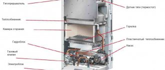
Gas boilers are often used to heat houses - convenient and quite economical appliances that run on blue fuel. The correct functioning of these devices is ensured by a number of devices that monitor the operating mode.
Timely adjustment of the gas boiler automation allows you to increase the efficiency of the heating device, as well as ensure reliability and safety in operation. And this, you see, is a rather important point for all users.
But how to make the adjustment and is it possible to do it on your own? Let's try to figure out these issues together. For this purpose, let’s take a closer look at the design and operating principle of the automation using the example of one of the most popular models.
We will also pay attention to the issues of setting up the equipment and the main problems that the user may encounter in the process of setting up and further operating the gas boiler.
Types and principle of operation of automation for boilers
This definition means a system of actuating and control devices aimed at maintaining specified modes, as well as promptly responding to emergency situations.
This ensures the safe use of boilers with minimal human involvement in the processes occurring in the device.
The design of gas boilers includes various types of automatic devices (electronic and mechanical) that are designed to maintain efficient, safe operation
All automation used for the correct functioning of heating devices can be divided into two fundamental groups:
- autonomous, not dependent on external power supply;
- devices that require an external source of electrical current to operate.
Let's look at each group of devices in detail.
How do energy-dependent devices function?
Such systems are complex electronic units that require electricity to operate.
At the same time, these devices allow you to regulate the fuel supply and the degree of heating by turning off or opening the tap, which helps save heating costs.
The operation of the electronic system is carried out on the basis of information transmitted by sensors to the control unit. After analyzing and processing the data on the controller and microprocessor, the commands are sent to the boiler drives
Problems solved by automatic devices:
- opening/closing the gas supply system valve;
- starting the device in automatic mode;
- preset or emergency shutdown of the boiler;
- adjusting the burner flame level using the existing temperature sensor;
- displaying data on the screen for visual reading (air temperature, water heating level, etc.).
In addition, modern automatic devices can have a number of additional functions that greatly facilitate the operation of boilers.
These include:
- management of equipment operation and monitoring of its functioning;
- protection of the heating system from malfunctions of the three-way valve;
- protection of equipment from freezing (if the temperature in the room suddenly drops, the device automatically starts the boiler into operation);
- self-diagnosis, which allows you to detect defects in components and parts, as well as identify malfunctions in the functioning of components. This option allows you to timely identify a malfunction that could lead to a serious breakdown requiring major repairs or a complete replacement of the boiler.
At the same time, reliable and stable operation of electronic automation devices for gas boilers can only be carried out under certain conditions.
Namely:
- no power surges;
- strict adherence to the recommended temperature regime;
- no problems associated with long service life.
If these rules are violated, high-tech devices can quickly fail.
There is a wide range of such automation on the market, which may involve programming or do without it. Such devices include the devices listed below.
Thermostat for measuring room temperature
The air temperature measurement sensor is located in the room, but is connected by cable to a boiler located in this or another room. The device not only monitors the heating level of the room, but also regulates the operation of the heating device.
As soon as the temperature drops below the designated level, the thermal device sends a signal to the boiler, upon receiving which the heating equipment automatically starts working.
Separate control units provide the ability to connect a temperature sensor located in the room. In this case, the set temperature will be automatically maintained in the heated space
When a comfortable level of air temperature in the device is reached, the valve closes, after which the operation of the boiler, and, consequently, the heating of the room stops, which helps to save fuel.
Our other article contains detailed information about the types and connection diagrams of a thermostat for a heating boiler.
Daily programmer for 24 hours
Like a regular thermostat, the device regulates the operating mode of a gas boiler, but has expanded capabilities.
Using this device, you can set a program for the operation of heating equipment for 24 hours, providing different levels of heating during certain periods of the day (for example, lowering the temperature in rooms at night or when people are unoccupied).
Most devices provide automatic repetition of the cycle, and to change it, you need to change the program. Connecting such a device can occur either using a cable or through a special radio channel.
Long term weekly programmer
Unlike the device described above, the weekly device allows you to schedule the operation of the boiler in advance for seven days at once.
Devices of this type, as a rule, provide several different modes, and it is also possible to create your own programs for the operation of heating devices.
Easy to program, the Auraton-2025 device has 3 factory and 7 user modes that allow you to optimally adjust the air temperature. Light sensor turns off the display at night, saving energy
All data is transmitted to a backlit display, which allows you to comfortably track information. Since the range of the programmer is 30 meters or more, it can be placed in living rooms.
Operating principle of non-volatile automation
At the same time, individual boiler parts that perform the control function do not require the use of electricity.
They are adjusted manually, as well as under the influence of geometric changes that occur in mechanisms under the influence of heat.
In mechanical devices, the boiler is started by pressing the washer on the valve. As a result of this, the latter opens in forced mode, letting in fuel that goes to the igniter
Despite the large range of models with electronic equipment, options with mechanical control are also very popular.
This can be explained by several reasons:
- Democratic price. Prices for such devices are significantly lower than for fully automatic analogues.
- Ease of use. The simplicity of the non-volatile automation device used in mechanical models allows even a person who is not related to technology to quickly understand the settings.
- Reliability. Mechanical devices do not depend on power surges or complete power outages, so they can function without a stabilizer, which is desirable when working with volatile equipment.
The disadvantages of such models include lower accuracy of adjustments, as well as the need to monitor the operation of the boiler.
As for the settings, it is done manually. Each mechanical device is equipped with a temperature scale, the numbers of which indicate the maximum values (from min to max). The operating temperature is set by selecting the required mark on the gradation bar.
After starting the unit, the thermostat is responsible for its operation. The operating element of this device is a rod, which, contracting when cooled, opens the gas supply valve, and then increases in size due to the increase in temperature and shuts off the flow of blue fuel.
Using a similar process, you can also reduce or increase the heat level.
Why does a gas boiler work without stopping - reasons and methods for eliminating them
Often, owners of gas units are faced with the problem that the gas boiler works without stopping. Such work leads to increased fuel consumption and is extremely uneconomical. Why is this happening? It is necessary to find the cause of the problem and fix it as quickly as possible.
Gas boilers operate on the following principle:
- the user sets the desired temperature value on the thermostat;
- the boiler begins to heat the coolant;
- when the required values are reached, the sensor sends a signal to the control board, which turns off the unit;
- when the coolant temperature drops, the heating is turned on again.
But it happens that the boiler has reached the desired temperature, but does not turn off. Why does a gas boiler work without stopping? Experts talk about a number of reasons.
The temperature sensor does not work
Temperature sensors are installed on the supply and return lines of the heating system. If at least one of them breaks, then it cannot send a signal that the required temperature has been reached. As a result, the gas boiler does not turn off. You can fix the situation like this:
- check the functionality of the sensors;
- inspect whether the wiring is connected to them correctly;
- clean oxidized contacts;
- replace the broken part.
Low return temperature
The coolant cools quickly if the room is poorly insulated or there is a leak somewhere in the system. With poor thermal insulation, the temperature of the liquid inside the system quickly cools down. The boiler, in turn, tries to maintain the desired temperature - as a result, it works constantly and does not turn off.
In this case, you need to better insulate your home, then the problem will disappear. For example, poor thermal insulation of a roof is determined by the size of the icicles - the more of them, the worse the thermal insulation. Snow accumulates on the roof and actively melts under the influence of escaping heat.
It is also necessary to check the heating system for leaks. If a leak is detected, the problematic element should be replaced.
The coolant moves slowly through the pipes
Slow circulation of coolant through the system is usually associated with clogged filters. You need to remove them and clean them of dirt.
Sometimes the reason lies in the operation of the circulation pump. It may be necessary to increase the coolant flow rate by adjusting the pump.
Clogged heat exchangers
If there is no filter at the entrance to the gas boiler, then deposits of potassium and magnesium salts gradually accumulate in the heat exchangers, which settle during heating. In this case, the heat exchanger, when heated, cannot transfer enough heat to the liquid, since it is hampered by a thick layer of deposits. As a result, the coolant does not warm up to the required temperature and the gas boiler operates without stopping.
This problem is solved by cleaning the clogged heat exchanger. A conventional circuit is quite easy to dismantle and clean with special reagents.
Note! If you have a gas boiler with a bithermic heat exchanger, then you will not be able to clean it. Due to its complex design, such a circuit becomes clogged faster than a regular one. You will have to purchase a new element and install it in place of the old one.
In order not to frequently clean the circuits from scale, it is recommended to purchase and install a magnetic filter that will prevent the deposition of salts.
Other reasons
Sometimes the reason that a gas boiler runs continuously is due to incorrect settings. It is possible that the thermostat is set to an insufficient temperature to heat the available area. Then it is necessary to adjust the optimal temperature.
If your unit has a modulation-type burner, you should make sure that its power is sufficient for heating. Perhaps you need to reconfigure it to a more productive level. Another reason could be a faulty outdoor thermostat programmer. You should check its functionality and replace faulty elements.
Continuous operation of a gas boiler is sometimes associated with errors in the piping. You need to check that all nodes are connected correctly.
The most serious reason, which cannot be eliminated on your own, is a malfunction of the electronic control board. Its diagnosis and repair should only be carried out by a service center specialist.
3 Comments
Source: https://oteple.com/pochemu-gazovyj-kotel-rabotaet-bez-ostanovki-prichiny-i-metody-ix-ustraneniya/
Elements of safety and comfortable operation
The group of automatic devices for boilers includes many elements that can be divided into two large groups: mechanisms that ensure safe operation, and devices that facilitate comfortable operation of the boiler.
The following parts are responsible for safe operation:
- thermostat;
- draft and flame control sensors;
- safety valve.
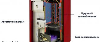
The flame control sensor consists of a thermocouple and an electromagnetic gas valve that shuts off or turns on the gas supply.
The flame temperature regulator ( thermostat ) maintains the required temperature of the coolant and also provides protection against overheating. This module turns the boiler on or off as soon as the coolant reaches a critical point (maximum or minimum).
The draft control module stops gas supply to the burner as soon as the location of the bimetallic plate changes due to increased temperature (it bends when heated, blocking the pipe through which the fuel is supplied).
We examined temperature, draft, pressure and flame sensors in more detail in this article.
The safety valve is used to regulate, distribute and shut off the gas flow
In a heating system, a safety valve is an integral component of pipeline fittings, which is important in controlling the volume of coolant involved in the circuit.
The hole in the valve through which gaseous fuel moves is called the seat. To turn off the device, you need to close it with a disk or piston.
Depending on the number of operating positions, gas valves can be one-, two- and three-stage, as well as modeling:
- Single-stage devices have only two operating positions: on/off.
- The two-stage device is equipped with one input and two outputs, and the valve opens when it is turned to an intermediate position, due to which the switching occurs more smoothly.
- A three-stage device is equipped with boilers that have two power levels.
- Modulating valves are used to smoothly change the power rating of devices.
Automation, used for convenience, includes options that are usually performed by users of heating systems. These include auto-ignition of the burner, self-diagnosis, selection of the optimal operating mode, and others.
Automation responsible for safety
According to the rules set out in the regulatory documentation ( SNiP 2.04.08-87, SNiP 42-01-2002, SP 41-104-2000 ), gas boilers must have a safety system. The purpose of this block is to urgently shut off the fuel supply in the event of any breakdown.
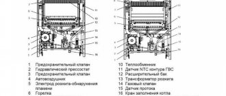
The presented diagram shows an automation system that allows you to regulate the functions of the gas device, with a detailed image of all the components
The principle of safe operation of the gas boiler automation system is based on monitoring instrument readings.
The control unit monitors the following factors:
- Gas pressure . When it drops to a critical level, the supply of flammable substances is immediately stopped. The process occurs automatically using a valve mechanism pre-set to a certain value.
- Gas supply . Responsibility for this property in volatile devices lies with the maximum or minimum relay. The mechanism of operation is to bend the membrane with the rod as the number of atmospheres increases, which leads to the opening of the contacts of the heating device.
- No flame in the burner . When the fire dies out, the thermocouple cools down, causing current production to stop, and the gas supply stops due to the gas valve being closed by the electromagnetic damper.
- Presence of traction . As this factor decreases, the bimetallic plate heats up, which causes a change in its shape. The modified element presses on the valve, which closes, stopping the flow of flammable gas.
- Coolant temperature . Using a thermostat, it is possible to maintain this factor at a given value, which helps prevent overheating of the boiler.
The possible malfunctions mentioned above can cause the main burner to go out, resulting in the possibility of gas entering the room, leading to fatal consequences.
This figure shows a schematic design of the functioning of the control automation, designed to prevent overheating of the system or other disturbances in its operation
To avoid this, all boiler models must be equipped with automatic devices. This is especially true for outdated models, where such devices have not yet been provided by manufacturers.
Why do you need gas automation?
Old-style boilers were manufactured in accordance with the gas parameters and heating system features that were in use several decades ago. These are, for example, models KChM, AOGV. At the same time, their durability allows them to be used for many years to come. But the problem with automation is that quite often it breaks down. In such a situation, there are three options:
- diagnose existing automation and replace the necessary parts;
- equip a reliable and high-quality unit with a modern automatic system;
- buy a new boiler.
The difference, of course, is in the price of the issue, the effort and time of the owner.
Let's consider the cheapest option - troubleshooting gas automation on an old boiler. However, first, let’s figure out why an automatic system is provided in the coolant in general.
Gas automation allows you to regulate and maintain the required level of coolant temperature, and also serves to automatically stop the gas supply in an emergency situation. Installing automation on an old gas boiler will allow you to be sure that if the burner flame goes out, then after a short time the system will work to stop the gas supply without your participation.
Attention! Automation, in addition to regulating and maintaining the temperature at a given level, ensures the safety of using the heating device and allows you to save on heat consumption.
If you want to change the automation, keep in mind that domestic manufacturers produce models that are suitable for almost any old coolant. Imported automation cannot be installed on everything. In addition, when installing foreign automation on old-style gas boilers, not all of its functions may work - the design features of the boiler will not allow it.
…
On a note! The choice of automation for gas boilers is varied. The most popular is the system from Italian manufacturers, for example, SIT. American automation (Honeywell) holds second place in popularity. There is a large selection of Russian (SABK, "Orion") and Ukrainian, "Iskra", "Plamya", APOK-1).
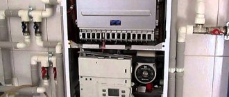
Features of the autoblock device
As a rule, manufacturers use special control units, which include the devices listed above. Despite their external differences, they all act on the basis of the same principles. To get acquainted with the best models and manufacturers of automation, follow this link.
The most widely used products are the Italian brand EuroSIT. The most popular model is Eurosit 630, which is characterized by easy functionality, compatibility with designs from various manufacturers, reliability and durability.
Using Eurosit 630 as an example, we will consider in detail the design of the automatic block.
Detailed design of the automatic control unit Eurosit 630, which is equipped with a significant part of modern gas boilers produced by different manufacturers
The device is a casing containing all structural components (spring valve, pressure regulator module, shut-off valve), which makes its installation much easier.
A pipe is connected to the body through which gas is supplied, as well as cables from sensors and other devices.
In addition to the Eurosit 630 block, there are also other models on the market: SABC, “Vakula” SIT, Dungs, Honneywell, which include sets of valves, pressure stabilizers, filters, temperature regulators
There are some difficulties when installing and setting up this device, but once you get used to it, you can practically not worry about the operation of the gas boiler.
Conclusions and useful video on the topic
It is explained in detail and clearly why the wick on a boiler with automatic EuroSIT 630, which is equipped with many Lemax models, does not light up, is described in this video:
You can get acquainted with the Lemax boiler, which operates under electronic control, in the following review:
Now you know what to do if one day your gas boiler does not start. Stay calm and check everything step by step - and you will probably be able to restore heating in your house.
What model of Lemax gas boiler do you have installed? Did you have any problems launching it and how did you solve the problem? Tell other visitors to our site about this - join the discussion in the comments.
How to set up the automatic heating device?
The adjustment involves setting up the EUROSIT 630 controller, which maintains the temperature regime of the liquid in the circuit, and in a critical situation blocks the gas supply.
Before setting up the automation of various models of gas boilers, you should install the equipment, strictly following the drawing. In this case, it is important to check the complete set of device parts, which must match those stated in the instructions.
The adjustment is carried out using a knob that allows you to control the transfer of the boiler to three positions:
- shutdown;
- ignition;
- setting the temperature mode (from 1 to 7).
To turn on the ignition device, the lever must be moved to the second position, placing it opposite the icon with the image of a spark.
When pressed, the piezo ignition button will be activated, causing the pilot burner to light. In this case, the lever must be held in this position for 10-30 seconds. After releasing the button, the igniter should stop working.
When the flame is ignited, the thermocouple heats up, due to which an EMF (25 mV) begins to be generated in it. This leads to the formation of a chain, the links of which are the sensor and the solenoid valve
When the lever is pressed, the solenoid valve opens and gas is supplied to the igniter (it should be left open even after the handle is released).
In this case, the thermocouple must provide protection against the return of fire. The sensors, which are elements of the circuit, are closed in the working position. After receiving the signal, they open, which causes the unit to shut down.
Problems when turning on the ignition device
If you have difficulty turning on the device, you can use the following instructions. First of all, you need to stock up on the necessary equipment, namely open-end wrenches, a screwdriver, a multimeter, pliers, and alcohol for cleaning parts.
Carefully remove the terminals of the device: they are shorted together, then tightened with pliers. To determine the cause of the malfunction, you need to turn on the igniter.
If ignition occurs normally, most likely there is a breakdown in the draft sensor. In this case, it is necessary to unscrew this element (to prevent overheating, it is surrounded by paronite gaskets).
When externally examining the device, you should pay attention to its contacts, which must be securely fixed to the body and not have any traces of oxidation on the surface. The temperature in the open state should be 75 °C
After this, using a tester you need to measure the resistance, the value of which should be 1-2 ohms. If a malfunction is detected, this part must be replaced. If the element functions normally, it is enough to wipe it with alcohol, after which the device is reinstalled.
To identify problems in the thermocouple traction breaker, the terminals are removed, after which the resistance is checked, the value of which should be equal to 3.
If the obtained value does not correspond to the optimal value, you need to use wrench No. 9 to unscrew the nut that secures the thermocouple to the traction breaker, after which use wrench No. 12 to unscrew the latter half a turn.
After this, you need to remove the plastic insert with contacts, then the part is completely unscrewed. The thermocouple is checked: it should be connected to the solenoid valve and secured with key No. 9. If after this ignition is still not possible, the problem lies in this part.
To resolve the issue, the nut securing the thermocouple to the igniter is unscrewed with a No. 10 wrench, after which the element is installed in the desired position.
To evaluate the result of the work, you need to measure the EMF (it should be equal to 18 mV), then clean the thermocouple contact and the elements of the traction breaker with alcohol. The final stage is assembling the device.
Troubleshooting other problems with automation
A common reason for lack of ignition is contamination of the insulator along which the wire leading into the combustion chamber is laid. Such a malfunction can be easily eliminated by wiping this part with a soft cloth. If it is heavily soiled, it can be moistened with solvent and then wiped dry.
Soot deposits that form inside the combustion chamber can also prevent the pilot from turning on. This defect can be easily eliminated by tapping the tube supplying gas to the burner.
After a break in operation, it is recommended to check the condition of the pipes. If not used, spiders may build nests in them or other insects may get in, which may impede gas flow.
High-tech models of gas boilers are equipped with sophisticated electronics. As a rule, information about problems is displayed on the display in the form of a code with a specific error
Poor water heating may indicate too large deposits on the walls of the heat exchanger. To solve the problem, it is advisable to rinse the circuit with hot water with the addition of a mineral solvent.
If this does not help, it is better to contact a specialist, as the cause may be damage to the electronics or the flow sensor.
In boilers that are too powerful, a “clocking” effect may occur, which manifests itself in too frequent switching on caused by intense heating of the gas. To correct the situation, it is recommended to reduce the fuel consumption supplied to the burners.
In mechanical devices, this can be achieved by rotating the adjustment lever on the gas valve, and in electronic models it is enough to use the control panel, where the corresponding operating parameter is set.
To extend the life of the equipment and gas boiler, it is recommended to carry out regular inspection and maintenance. We discussed how to perform maintenance correctly in the next article.
Automatic blocks of floor-standing boilers
The vast majority of floor-standing gas boilers are equipped with automatic safety systems that operate without an external power source (non-volatile). According to the requirements of regulatory documents, automation equipment must shut off the gas supply to the burner and igniter in three emergency cases:
- Extinction of the main burner flame due to blowing out or for other reasons.
- When natural draft in the chimney channel is absent or sharply reduced.
- The drop in natural gas pressure in the main pipeline is below a critical level.
For reference. The implementation of the listed functions is mandatory for gas boilers of all types. Many manufacturers add a fourth level of safety – overheating protection. When the coolant temperature reaches 90 °C, the valve, based on a signal from the sensor, stops supplying gas to the main burner.
Various models of gas floor-standing boilers from different manufacturers use the following types (brands) of non-volatile automation:
- Italian blocks EuroSIT (Eurosit) series 630, 710 and 820 NOVA (heating units Lemax, Zhitomir 3, Aton and many others);
- Polish devices "KARE" (heat generators "Danko", "Rivneterm");
- American automatic control devices Honeywell (Zhukovsky heaters);
- domestic products, "Arbat".
Fuel supply system in the simplest AOGV devices equipped with ZhMZ valves.
The burner is hidden in the lower part of the housing. We have listed the most common brands of automation, which are often installed on water heating boilers from the same company. For example, the Zhukovsky plant equips budget versions of AOGV devices with its own ZhMZ safety units, mid-price heat generators with EuroSIT devices, and powerful models with Honeywell automatic valves. Let's look at each group separately.
SIT Group brand gas valves
Of all the types of automation found in boiler installations, EuroSIT safety units are the most popular and reliable in operation. They are recommended by companies that supply natural fuels, including for replacing old gas equipment of KChM, AGV boilers, and so on. They work without problems as part of micro-flare burners Polidoro, Iskra, Vakula, Thermo and others.
The exact names of the three models used look like this:
- 630 SIT;
- 710 MiniSIT;
- 820 NOVA.
The thermocouple, main and pilot burner connection sockets are located on the bottom panel of the valve
For reference. SIT Group has ceased production of the 630 and 710 series, considering them obsolete. This has been replaced by new safety automatics for heating boilers - gas valves 820 NOVA, 822 NOVA, 840 SIGMA and 880 Proflame (battery operated). But old products are not difficult to find on sale.
In order not to bore you with the design details of automatic EuroSIT devices, let us briefly explain the operating principle using the example of a simple 630 series unit:
- When you turn the handle to the “ignition” position and press from above, you forcibly open the solenoid valve, which allows gas to flow to the pilot burner (igniter). You click the button on the piezoelectric element, which produces a spark that ignites the wick.
- By holding the main handle for 30 seconds, you allow the thermocouple to be heated by the pilot flame. The thermal balloon produces a voltage (EMF) of 20-50 millivolts, which fixes the electromagnet in the open state. Now you can release the handle.
- Set the main handle to the desired position and thus supply gas to the main burner. The latter ignites and begins to heat the heat exchanger with water from the heating system, as shown in the diagram.
- When the water reaches a certain temperature, the capillary sensor is activated, gradually closing the second valve - the thermostatic one. The supply of fuel to the burner device stops until the sensor cools down and the valve plate opens the path for gas. The igniter continues to burn in standby mode.
Note. Older automation modifications were not equipped with temperature sensors and ignition units, so matches were required to start the heat generator.
Connection diagram of the automation unit to the gas burner device.
A diaphragm valve, which plays the role of a pressure regulator, is responsible for the normal supply of gas in the device. When it falls below a preset value, the fuel channel closes and an emergency shutdown of the boiler occurs. Other situations that lead to refusal include:
- The burner and the wick heating the thermocouple go out. Voltage generation stops, the solenoid valve closes the fuel passage.
- If the draft in the chimney suddenly disappears, the sensor placed in this channel overheats and breaks the power supply circuit of the electromagnet. The result is similar - the fuel supply is blocked.
- In heaters equipped with overheating sensors, the electrical circuit is broken after the water reaches a temperature of 90-95 °C.
When the gas automatic system triggers an emergency shutdown, the user is blocked from restarting the boiler for 1 minute; before that, the fuel supply will not resume. The operation of the system is clearly reflected in the training video:
Differences between models 710 MiniSIT and 820 NOVA
According to the principle of operation, these units do not differ from their predecessor - the 630 series. Changes to the 710 MiniSIT automation are purely constructive:
- 2 buttons “Start” and “Stop” are placed separately along with the solenoid valve;
- the main handle only rotates the thermostat rod and regulates the temperature of the coolant;
- the ignition unit with a piezo igniter button is built into the product body;
- The basic package of the device includes a bellows-type temperature sensor with a capillary tube;
- added gas pressure stabilizer.
In the 710 MiniSIT unit, the handle acts as a temperature regulator and switches the heater to standby mode with the pilot light on.
For reference. In the first versions of the 710 family, a spark igniter was not provided.
The latest 820 NOVA product line includes changes to improve stability, reliability and throughput. We want to highlight 2 improvements that are important from a user point of view:
- The product is equipped with a connector for connecting a room thermostat and weather-dependent automation. Now the heating unit is able to maintain the air temperature in the apartment.
Connection diagram for a remote thermostat with an external power source - A modification has appeared with its own power source - a thermogenerator mounted on a bar next to the pilot burner, as shown in the diagram. The principle of operation is similar to a thermocouple, but the magnitude of the generated EMF is much greater.
Non-volatile circuit for connecting a room thermostat
In this section, it makes sense to mention Honeywell automatic gas valves, which operate according to a similar circuit. Their main difference is their increased throughput, which allows the units to be used in high-power boilers (30-70 kW).
Polish automatic "Kare"
Few manufacturers practice installing Polish security systems on gas boilers. The reason is banal: in terms of reliability, the product is inferior to products from Italy, the USA and Germany, but the price is more expensive than domestic boiler automation.
We called the product a “system” because it consists of several blocks, although the general principle of operation remains unchanged:
- gas filter;
- valve – gas pressure regulator;
- there is a separate thermostat with a control knob;
- membrane thermostatic valve;
- piezoelectric igniter button.
Diagram of the Polish “Kare” system.
The nodes and sensors are connected to each other by capillary tubes. Essentially, this is the same SIT or Honeywell device, only broken down into separate parts. This is a plus: changing parts is more convenient and cheaper.
Products of domestic companies
As you understand, boiler automation made in the post-Soviet space does not contain any revolutionary solutions or technological breakthroughs. To implement three safety functions, the same principles are used - turning on an electromagnet with voltage (EMF) of a thermocouple, a membrane gas valve and a traction sensor that breaks the circuit.
ZhMZ safety valve diagram
It makes no sense to talk in detail about the design of blocks from the brands SABK, Orion and ZhMZ (Zhukovsky Plant). The listed products are distinguished by their simplest design, low cost and low reliability. Thermocouples burn out almost every year, and the thermostat turns off and starts the burner too abruptly, causing a loud bang that sometimes resembles a micro-explosion.
The devices work normally in the first years of operation, then they need to be monitored and promptly serviced, fortunately, spare parts are available for sale and are inexpensive. For an example of troubleshooting a typical ZhMZ automation fault, see the video: