Features of connection to the hot water supply system
If a separate outlet is used for the towel dryer (series connection to the hot water supply system), and the water from it is removed through sources inside the apartment, then installing the heated towel rail on hot water is carried out without additional work. But with this connection of the towel dryer, the temperature of the hot water decreases. It is usually used in small houses.
Prices for different types of dryers in the store
More often, the device is connected to the water supply, replacing part of the riser; this can be seen in the bathroom in a panel house. When installing a heated towel rail on a hot water supply riser, additional insurance is required in the form of a bypass.
Plate heat exchangers application areas
Plate heat exchangers are used in home heating systems, hot water supply, air conditioning systems in large cottages, schools, gardens, swimming pools, in entire neighborhoods, as well as in the heating system of rural houses. Plate heat exchangers are widely used in the food industry.
Heat exchangers for heating have a number of undeniable advantages over other devices used to create a suitable microclimate.
Such heating devices have a number of advantages over other types.
Positive traits
Among the main positive qualities of a device that provides heating, the following can be noted:
- high level of compactness;
- plate heat exchangers have a high heat transfer coefficient;
- heat loss coefficient is as low as possible;
- pressure losses are at a minimum level;
- installation, commissioning, repair and insulation work requires low financial costs;
- in case of possible clogging, this device can be disassembled, cleaned and reassembled by just two workers in 4-6 hours;
- it is possible to add power to the plates.
https://youtube.com/watch?v=pOTVV58Rj3U
In addition, due to its simplicity, the connection of the heat exchanger to the heating system can be carried out simply on the floor in the heating substation or on the usual supporting structure of the block heating substation. Separately, it is worth noting the low level of contamination of the heat exchanger surface, which is caused by the high turbulence of the liquid flow, as well as due to the high-quality polishing of the heat exchange plates used. Today, the service life of sealing gaskets from leading European manufacturers is at least 10 years. The service life of the plates is 20-25 years. The cost of replacing the sealing gasket can be 15-25% of the total cost of the entire unit.
It is very important that after a detailed calculation, the design of a modern plate heat exchanger can be changed to meet the necessary characteristics specified in the technical specifications (design variability and task variability). Absolutely all plate heat exchangers are resistant to high levels of vibration
With modern heating system devices, the consequences of possible water hammer are reduced to almost zero.
Monoblock plate heat exchanger. What are the advantages and disadvantages?
The two-stage mixed-type hot water system is currently widely used in the housing and communal services sector. In an individual heating point (IHP), the main link of this system is a plate heat exchanger - a monoblock. It is a two-stage plate heat exchanger. The first and second stages of the heat exchanger are enclosed in one housing. To operate this type of heat exchanger, 6 pipes are needed for the inlet and outlet of working media. The number of working media can reach 4 pieces: - Heated medium (usually cold tap water) - Heating fluid (boiler room, heating networks) - Coolant from the “return” of the heating heat exchanger
Let us consider, using an example, the principle of operation of a monoblock heat exchanger of a hot water supply system. The main task of this heat exchanger is to heat cold tap water from 5C to 60C. Unlike a standard hot water heat exchanger, heating occurs in two stages. Heating of cold water in the first stage occurs from 5C to 33C, while the heating fluid 70C comes from the heating network. In the second stage, cold water is heated from 33C to 60C, and we add coolant from the “return” of the heating heat exchanger to the heating fluid from the heating network. The temperatures we indicated are approximate; they may differ depending on the heat source and operating conditions.
The main area of application of monoblock heat exchangers is hot water supply systems. This equipment is also used for cooling food media (wort, milk...), when two different coolers are used in the system.
So that you can understand how appropriate it is to use this type of equipment in your engineering system, we propose to consider the advantages and disadvantages of a monoblock heat exchanger.
Advantages: - Compact dimensions. Let us repeat that the monoblock consists of two heat exchangers combined into one housing. This will always take up less space than two separate heat exchangers. - Price. Two heat exchangers in one housing are always cheaper than installing two separate heat exchangers. - Savings on piping. Piping a monoblock heat exchanger, even with 6 pipes, will cost less than piping two separate heat exchangers. You will be able to save money mainly through pipeline fittings.
Disadvantages: - Difficulty connecting. Due to the close location of all 6 pipes, it is difficult to carry out welding and installation work to connect the heat exchanger to utility networks. This is especially felt in close quarters of heating stations. — Difficulty of maintenance. In the monoblock on the back plate there are two pipes to which pipelines are connected. This makes it immobile and creates difficulties when disassembling the heat exchanger. Carrying out maintenance work is much more complicated, unlike a conventional heat exchanger with a movable back plate. - Reliability. If the monoblock heat exchanger breaks down, we end up with a completely failed hot water system. In the case of operating two separate heat exchangers, if one of them breaks down, we will be able to continue operating at 50% load. - Difficulty of calculation. There are several difficult aspects to this heat exchanger that need to be calculated accurately. 1) Mixing of coolant from the heating heat exchanger to the heating coolant. 2) Keep hydraulic losses in both stages, etc., within the calculation framework.
To summarize, two separate heat exchangers are always more reliable than one heat exchanger for the same task. But the monoblock allows you to save money. In this situation, when choosing between a monoblock and two separate heat exchangers, you should choose the optimal balance between reliability and cost savings.
An example of calculating a monoblock plate heat exchanger for a domestic hot water system.
The heat exchanger production time is 1 day. The price of the heat exchanger is 115,000 rubles.
What does a modern heat exchanger consist of?
A modern type heat exchanger consists of several parts, each of which plays its own important role:
- a fixed plate to which all incoming pipes are connected;
- pressure plate;
- heat exchange plates with inserted sealing type gaskets;
- top and bottom guides;
- rear pillar;
- threaded studs.
This image shows a shell and tube heat exchanger.
Thanks to this unique design, the heat exchanger is able to provide the most efficient layout of the entire surface of the heat exchanger used, which makes it possible to create a heating apparatus that is small in size. Absolutely all the plates in the assembled package are identical, only some of them are turned to the other at an angle of 180 degrees. That is why channels must be formed during the necessary contraction of the entire package. It is through them that during the heating process the working fluid flows, taking part in heat exchange. Thanks to this arrangement of system elements, correct channel alternation is achieved.
Today we can safely say that plate-type heat exchangers are more popular due to their technical characteristics. The key element of any modern heat exchanger is the heat transfer plates, which are made of steel that is not subject to corrosion; the thickness of the plates ranges from 0.4 to 1 mm. For production, a high-tech stamping method is used.
During operation, the plates are pressed against each other, thereby forming slot channels. The front side of each of these plates has special grooves, where a rubber contour gasket is specially installed, which ensures complete sealing of the channels. There are four holes in total, two of them are necessary to ensure the supply and removal of the heated medium to the channel, and the other two are responsible for preventing cases of mixing of the heating and heated medium. In the event of a breakthrough in one of the small circuits, the plate heat exchangers are protected by drainage grooves.
If there is a large difference in the flow of media and a very small difference in the final temperatures, then it is possible to repeatedly use the heat exchange process, which will occur through a loop-shaped flow direction.
Using plate-type heat exchangers to provide domestic hot water
Heating water through heating networks is useful in economic terms, since heat exchangers, when compared with classic boilers using electric or gas energy, work only for the heating system, and nothing else.
As a result, the cost of hot water per liter will be much lower. Plate-type heat exchangers use heat energy in heating networks to heat ordinary tap water. Heated by heat exchange plates, hot water penetrates all water distribution points, including faucets, taps, and showers.
It is also important to take into account that the water being heated and the water, which is a heat carrier, do not interact with each other in any way within the heat exchanger. The media for water flow are separated from each other by plates placed in a heat exchanger, so heat exchange passes through them.
It is impossible to use water in heating systems to meet domestic needs; it is harmful and irrational. This is explained by the following reasons:
- 1. The processes of water preparation for equipment and boilers is an expensive and, most often, complex procedure that requires special knowledge, experience and skills.
- 2. In order to soften the water and make it less hard for the heating system, reagents and chemicals are used that have a negative impact on human health.
- 3. Over many years, heating pipes accumulate a large amount of deposits, which are also harmful to humans and their health.
However, no one prohibits the use of such water not for its intended purpose, but indirectly, because the heat exchanger for hot water is characterized by high efficiency indicators.
Two-stage sequential circuit.
The network water branches into two streams: one passes through the PP flow regulator, and the second through the second stage heater, then these streams are mixed and enter the heating system.
At a maximum return water temperature after heating of 70ºС
and the average load of hot water supply, tap water is almost heated to normal in the first stage, and the second stage is completely unloaded, because The RT temperature regulator closes the valve to the heater, and all network water flows through the PP flow regulator into the heating system, and the heating system receives more heat than the calculated value.
If the return water after the heating system has a temperature of 30-40ºС
, for example, when the outside air temperature is above zero, then heating the water in the first stage is not enough, and it is heated in the second stage. Another feature of the scheme is the principle of coupled regulation. Its essence is to configure the flow regulator to maintain a constant flow of network water to the subscriber input as a whole, regardless of the hot water supply load and the position of the temperature regulator. If the load on the hot water supply increases, then the temperature regulator opens and passes more network water or all the network water through the heater, while the water flow through the flow regulator decreases, as a result, the temperature of the network water at the entrance to the elevator decreases, although the coolant flow remains constant. The heat not supplied during periods of high hot water supply load is compensated during periods of low load, when a flow of increased temperature enters the elevator. There is no decrease in air temperature in the premises, because The heat-storing capacity of building envelopes is used. This is called linked regulation, which serves to level out the daily unevenness of the hot water supply load. In the summer, when the heating is turned off, the heaters are switched on in series using a special jumper. This scheme is used in residential, public and industrial buildings with a load ratio. The choice of scheme depends on the schedule of central regulation of heat supply: increased or heating.
Advantage
A sequential scheme compared to a two-stage mixed scheme is the equalization of the daily heat load schedule, better use of the coolant, which leads to a reduction in water consumption in the network. The return of network water at a low temperature improves the heating effect, because Low pressure steam extraction can be used to heat water. The reduction in network water consumption under this scheme is (per heating point) 40% compared to parallel and 25% compared to mixed.
Flaw
– lack of possibility of full automatic regulation of the heating point.
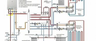
Connection diagrams
A heat exchanger operating on the water-to-water principle has several different connection schemes, however, the primary type circuits are mounted to the distribution pipes of the heating network (it can be private or implemented by city services), and the secondary type circuits are mounted to the water supply pipeline.
Most often, it depends only on design decisions what type of connection is allowed to be used. Also, the installation diagram and its choice are based on the standards of “Design of Heating Stations” and in the SP standard under number 41-101-95. If the ratio and difference of the maximum possible water heat flow for hot water supply to the heat flow for heating is determined in the range from ≤0.2 to ≥1, then the basis is a connection diagram in one stage, and if from 0.2≤ to ≤1, then from two degrees .
Standard
The simplest and most cost-effective scheme to implement is parallel. With this scheme, heat exchangers are mounted in series with respect to the control valve, that is, the shut-off valve, and also in parallel with the entire heating network. In order to achieve maximum heat exchange within the system, high heat carrier flow rates are required.
Two-stage scheme
Two-stage mixed system
If you use a two-stage scheme, then water is heated either in a pair of independent devices or in a monoblock installation. It is important to remember that the installation scheme and its complexity will depend on the overall network configuration. On the other hand, with a two-stage design, the efficiency level of the entire system increases and the consumption of coolants decreases (by about 40 percent).
With this scheme, water preparation occurs in two steps. The first step uses thermal energy to heat the water to 40 degrees, and the second step heats the water to 60 degrees.
Serial connection
Two-stage sequential circuit
This circuit is implemented within one of the devices for DHW heat exchange, and this type of heat exchanger is much more complex in design when compared with standard circuits. It will also cost much more.
Dependent circuit with three-way valve and circulation pumps
Dependent diagram for connecting a heating point of a heating system to a heat source with a three-way valve for a heat flow regulator and circulation and mixing pumps in the supply pipeline of the heating system.
This scheme in ITP is used subject to the following conditions:
1 The temperature graph of the heat source (boiler room) exceeds or is equal to the temperature graph of the heating system. A heating point connected according to this principle diagram can operate either with or without an admixture to the supply flow from the return pipeline, that is, to let the coolant from the supply pipeline of the heating network directly into the heating system.
For example, the calculated temperature graph of a heating system is 90/70°C, equal to the temperature graph of the source, but the source, regardless of external factors, always operates with an outlet temperature of 90°C, and for the heating system, it is necessary to supply coolant with a temperature of 90°C only at the calculated temperature. outside air temperature (for Kyiv -22°C). Thus, at the heating point, the cooled coolant from the return pipeline will be mixed with the water coming from the source until the outside air temperature drops to the calculated value.
2 The heating point is connected to a free-flow collector, hydraulic arrow or heating main with a pressure difference between the supply and return pipelines of no more than 3 m of water column.
3 The pressure in the return pipeline of the heat source in static and dynamic modes exceeds the height from the point of connection of the heating point to the top point of the heating system (building static) by at least 5 m.water.st.
4 The pressure in the supply and return pipelines of the heat source, as well as the static pressure in the heating networks, do not exceed the maximum permissible pressure for the heating system of the building connected to this ITP.
5 The heating point connection diagram must ensure automatic high-quality regulation of the heating system according to a temperature or time schedule.
Description of the operation of the ITP circuit with a three-way valve
The principle of operation of this scheme is similar to the operation of the first scheme, with the exception that the three-way valve can completely shut off the selection from the return pipeline, in which all the coolant coming from the heat source without admixture will be supplied to the heating system.
If the supply pipeline of the heat source is completely blocked, as in the first scheme, only the coolant that comes out of it, taken from the return, will be supplied to the heating system.
Dependent circuit with three-way valve, circulation pumps and differential pressure regulator.
It is used when the pressure drop at the point of connection of the ITP to the heating network exceeds 3 m of water column. The differential pressure regulator in this case is selected to throttle and stabilize the available pressure at the inlet.
Operating principle of the Ridan plate heat exchanger
Heat transfer in plate heat exchangers is carried out from the hot coolant to the cold (heated) medium through corrugated steel plates, which are installed in a frame and pulled together into a package. During the heat exchange process, liquids move towards each other (in countercurrent). In places where they can flow, there is either a steel plate or a double rubber seal, which virtually eliminates the mixing of liquids. All the plates in the plate heat exchanger package are the same, only they are rotated one after the other by 180°, so when the plate package is pulled together, channels are formed through which the liquids participating in the heat exchange flow. This installation of the plates ensures alternating hot and cold channels. The type of corrugation of the plates and their number installed in the frame depend on the operational requirements for the plate heat exchanger. Ridan heat exchangers use plates from the Danish company Sonde.
