Material and section shape
The first thing that is done at the stage of preparation for design is to select the material for the air ducts and their shape, because when gases rub against the walls of the duct, resistance to their movement is created. Each material has a different internal surface roughness, and therefore, when choosing air ducts, the resistance to air flow will be different.
Depending on the specifics of the installation, the quality of the air mixture that will move through the system and the budget for the work, choose stainless, plastic or galvanized steel channels with a round or rectangular cross-section.
Rectangular pipes are used most often to save usable space. Round ones, on the contrary, are quite bulky, but have better aerodynamic performance and, as a result, a noisier design. For the correct construction of a ventilation network, important parameters are: the cross-sectional area of the air ducts, air flow and its speed when moving through the channel.
The shape does not affect the volume of transported air masses.
Natural ventilation
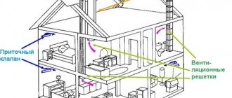
Natural ventilation of rooms occurs due to the influence of wind and gravity. With natural ventilation, air can enter and be removed from the room through specially provided openings, as well as through leaks in the external fences of the building, as well as through special channels.
Exhaust natural duct ventilation is carried out mainly in residential, public and administrative buildings for premises that do not require air exchange more than once.
Exhaust ventilation systems with natural impulse for residential, public and administrative buildings are calculated on the difference in the specific gravities of external air with a temperature of 5 °C and internal air with a temperature for the cold period of the year. It is believed that at higher outside temperatures, when natural pressure becomes very insignificant, additional air exchange can be obtained by opening vents, transoms, and sometimes window frames more often and for a longer time.
In industrial buildings, natural ventilation should be designed if it ensures normal indoor air conditions and if it is acceptable according to technological requirements.
Natural ventilation systems for industrial premises are calculated:
a) the difference in the specific gravities of external and internal air according to the calculated parameters of the transition period of the year for all heated premises, and for rooms with excess heat - according to the calculated parameters of the warm period of the year;
b) to the effect of wind at a speed of 1 m/s in the warm season for rooms without excess heat.
Exhaust natural duct ventilation, fig. 5.4, consists of vertical intra-wall or attached ducts with openings closed with louvered grilles, prefabricated horizontal air ducts and an exhaust shaft.
Rice. 5.4. Scheme of natural exhaust duct ventilation
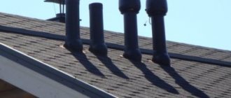
To enhance air extraction from rooms at the top of the shaft, a special attachment is often installed - a deflector. Polluted air from the premises enters through the louvered grille into the channel, rises upward, reaching the prefabricated air ducts, and from there exits through the shaft into the atmosphere. To install duct ventilation, special ventilation panels or blocks with ducts of round, rectangular or oval cross-section are made. The most rational cross-sectional shape of the channel and air duct should be considered round, since compared to other shapes, with the same area, it has a smaller perimeter, and, consequently, a smaller amount of friction resistance during air movement. Ventilation ducts for natural ventilation in civil and administrative buildings, as a rule, are laid in the thickness of the walls; they can be made in the form of ventilation blocks, be attached or hemmed, depending on the structural design of the building and the interior decoration of the premises.
In ducted natural exhaust ventilation systems, air moves in ducts and ducts under the influence of natural pressure resulting from the temperature difference between cold external and warm internal air.
Natural pressure ΔRe is determined by the formula
ΔRe = hi g (ρн – ρв), Pa, (5.19)
where hi is the height of the air column, m; g = 9.81 m/s2 – free fall acceleration; ρн – density of outside air at a temperature depending on the purpose of the room, kg/m3; ρв – density of internal air, kg/m3.
The height of the air column hi should be taken:
- for exhaust air ducts if there is only a hood in the room - from the middle of the exhaust opening to the mouth of the exhaust shaft; if there is an inflow in the room - from the middle of the height of the room to the mouth of the exhaust shaft;
- for supply air ducts - from the middle of the height of the supply chamber to the middle of the height of the room.
Air density is determined using tables from reference literature or using the formula:
, kg/m3, (5.20)
where t is air temperature, °C.
Analyzing expression (5.19), we can draw the following practical conclusions.
1. With natural ventilation, the upper floors of the building, compared to the lower floors, are in less favorable conditions, since the available pressure here is less.
2. Natural pressure becomes high at low outside temperatures and decreases noticeably in the warm season.
In addition, natural pressure does not depend on the length of horizontal air ducts, whereas to overcome resistance in short branches of air ducts, less pressure is required than in branches of considerable length. The radius of action of exhaust systems - from the axis of the exhaust shaft to the axis of the most distant hole - is recommended to be no more than 8 m.
The area F, m2, and the cross-sectional dimensions of the channels a and b, m, are determined by the air speed in the channels, Vк, m/s, and the air flow in the channel, Lп, m3/s:
F = a × b = , m2. (5.21)
Then the pressure loss as air passes through the channel is calculated. For natural ventilation, the air speed in the channels is taken to be no more than 1.5-2 m/s. If, when calculating the ventilation network, it turns out that the pressure loss when moving air is ΔPpot = 0.9 ΔPe, the calculation is completed, otherwise the network or its individual sections are recalculated, changing the cross-section of the channels. To be able to use calculation tables of air duct resistance made for air ducts of round cross-section, with a square or rectangular cross-section, the so-called hydraulic diameter is determined:
dg = , m, (5.22)
where a and b are the transverse dimensions of the rectangular channel, m.
The total pressure loss ΔPc in the network consists of losses to overcome local resistance and to overcome air friction on the walls of the air ducts; they are determined by the formula:
, Pa, (5.23)
where z – local resistance coefficients; Vк – air speed in the channels, m/s; ρ – air density, kg/m3; R – pressure loss due to friction in the design section of the network, Pa/m (per 1 m of air duct length); l – length of air duct (channel) sections, m.
Deflectors are used to increase the available pressure. Deflectors are special nozzles installed at the ends of pipes or shafts, as well as directly above the exhaust openings in the roofs of industrial buildings. The purpose of the deflector is to enhance the extraction of polluted air from various rooms. The operation of the deflector is based on the use of the energy of air flow - wind, which, hitting the surface of the deflector and flowing around it, creates a vacuum near most of its perimeter, which enhances the extraction of air from the premises.
Deflectors are manufactured in various designs and sizes. The most common TsAGI deflectors are round (Fig. 5.5) and square shapes.
Rice. 5.5. TsAGI deflector:
1 – pipe; 2 – diffuser; 3 – deflector body; 4 – legs for attaching the umbrella-cap; 5 – umbrella-cap
The dimensions of the individual elements of the deflector are indicated in fractions of the diameter of its nozzle. The deflector number corresponds to the diameter of the pipe in decimeters. The square-shaped TsAGI deflector consists mainly of the same elements as the round one.
The vacuum created by the deflector depends on the wind speed Vв. Wind speed, Vв, is determined according to SNiP 23-01-99. The speed of air movement in the deflector pipe is approximately 0.2-0.4 of the wind speed, i.e.
Vd = (0.2—0.4) Vv, m/s. (5.24)
The vacuum created by the deflector is determined by the formula:
Pd = , Pa, (5.25)
where – are taken according to the schedule in Fig. 5.6 or a passport for the deflector, depending on the accepted ratio.
Rice. 5.6. Graph for determining the vacuum created by the deflector and the amount of air removed:
1 – with a round section; 2 - with a square section
It is recommended to install deflectors at the highest points of the building, directly blown by the wind. You cannot install deflectors in the area of wind pressure, for example, in front of a wall towards which the wind is directed, near protruding firewalls, etc., since under these conditions the draft may overturn, i.e., blowing outside air into the room. Deflectors should also not be installed between tall buildings (in aerodynamic shadows).
Louvre grilles are installed in places of air intake or distribution in supply and exhaust systems to regulate the amount of air entering or removing through the openings. The most widely used are louvered grilles with movable blind feathers; their standard sizes are given in reference books and standard drawings issued by the State Construction Committee of Russia. Using a cord or cable, the grille can be completely open, fully or partially closed. In gasified rooms, unregulated grilles are installed.
For increased requirements for interior decoration, gratings are made of metal, plastic, plaster and are given a variety of shapes and patterns. However, the hydraulic resistance of these grilles, as well as their live cross-sectional area (the live cross-section is the total area of the holes for air passage in the grille) must be the same as that of a standard grille. The open cross-sectional area of the gratings is determined by the formula
Fzh.s. = L / V, m2, (5.26)
where L is the volume of air passing through the grille, m3/s; V – air speed in the open section of the louvered grille, m/s.
The exhaust from the premises is regulated by louvered grilles in the exhaust openings, as well as throttle valves or gate valves installed in the prefabricated air duct and in the shaft.
Aeration of buildings
Aeration is an organized and controlled natural general ventilation through opening transoms of windows in the external enclosures of buildings and ventilation skylights using gravitational (thermal) and wind pressure. It is used for ventilation of buildings with large heat releases and allows for air exchanges reaching millions of m3 in 1 hour.
Transoms are installed with top, bottom or middle hangers. For the convenience of opening transoms from the floor level, it is necessary to install devices with mechanical or manual drives.
Ventilation and light (aeration) lanterns located at the highest point of the building contribute to the intensification of natural air exchange.
In order to avoid unwanted entry of outside air through the lantern, which causes the reverse movement of contaminated air from the upper zone to the working zone (overturning the draft), aeration lanterns are designed to be non-blown. In such lanterns, open openings are protected from the wind either by shields installed on the roof of the building or by the blank walls of the lantern. For relatively small air exchanges, deflectors are used that are installed on the roof of the building.
The supply of supply air to ventilated premises with natural ventilation should be provided at a level of no more than 1.8 m in the warm season and at least 4 m from the floor to the bottom of the ventilation openings in the cold season. In this case, the outside air, before entering the work area, mixes with the inside air and increases its temperature.
The supply of unheated air during the cold season at lower elevations (below 4 m from the floor) is permitted provided that measures are taken to prevent direct exposure to cold air on workers.
In buildings with natural ventilation (aeration), opening devices in windows should ensure that incoming air can be directed upward during the cold season and downward during the warm season (Fig. 5.7).
Rice. 5.7. Aeration of a single-bay workshop
a – pressure diagram; b- section of the workshop
Calculation of aeration consists of determining the required area of opening transoms (supply - for the warm period of the year, - for the transition period of the year, - for the cold period of the year and exhaust Fout).
When designing buildings, the required area of opening transoms is determined by considering the most unfavorable conditions when the wind speed is zero. The calculation is usually carried out first for the warm period of the year.
Calculation of aeration (natural general ventilation) of a production facility includes three stages:
1) calculation of the necessary air exchange in the room (according to parameters: excess heat, moisture, harmful substances);
2) calculation of air speed in ventilation openings (ducts);
3) calculation of the area of supply and exhaust openings.
The initial data for calculating aeration are:
— estimated summer outside air temperature for ventilation calculations, tн, °С;
— air temperature in the working area, tрз, °С;
— average air temperature in the workshop, tav, °C;
— temperature of the removed air, tух, °С;
— height of the centers of the supply aeration openings from the floor, hpr, m;
— height of the centers of exhaust aeration openings from the floor, hvyt, m;
— the amount of excess heat released in the room, Q, W;
— temperature gradient α (temperature change along the height of the room), °C/m, usually “for hot shops” is taken equal to 0.8–1.5 (more often taken α = 1.2–1.3);
— coefficients of local resistance of supply, zpr, and exhaust, zvyt, transoms;
— air density ρн, ρср, ρух at tн, tср and tух.
Calculation of the required air exchange in the room under consideration should be carried out based on the air and heat balance equations:
ΣGpr – ΣGух = 0; (5.27)
3.6 Qizb + ΣGpr·c·tpr – ΣGух c·tух = 0, (5.28)
where Gpr – mass flow of supply air, kg/h; Gux – mass flow rate of air removed from the room, kg/h; Qizb – excess heat input into the room, W; c – specific heat capacity of air, kJ/kg °C; tpr and tух – temperature of supply and exhaust air, °C.
Solving equations (3.27) and (3.28) together, we obtain
Gpr = Gух = , kg/h. (5.29)
Exhaust air temperature:
tух = tрз + α (hout – 2), °С, (5.30)
where α is the temperature gradient, °C/m; hvyt – height from the floor mark to the middle of the exhaust opening, m.
Average air temperature in the workshop:
tср = (tух + tрз) / 2, °С. (5.31)
To calculate aeration, conditional external pressures are used at the level of the middle of the supply and exhaust openings. Taking the workshop floor level as the reference level, these conditional pressures will be equal
Рп = g hр (ρн – ρср), Pa, (5.32)
Rvyt = g hvyt (ρн – ρср), Pa. (5.33)
The calculated pressure difference ΔР between the supply and exhaust openings, due to which outside air will enter the room
ΔР = Рп – Rvyt, Pa. (5.34)
To ensure low rates of entry of outside air and the stability of ascending convective flows, the area of the supply openings is made as large as possible. In the supply openings, it is recommended to spend from 0.1 to 0.3 of the calculated pressure difference ΔP, that is
ΔРп = (0.1 ... 0.3) ΔР,Pa, (5.35)
the remainder of the calculated pressure difference will be spent on the passage of air through the exhaust openings.
Indoor pressure
Рх = Рп - ΔРп , Pa. (5.36)
Mass velocity of air passing through the supply transoms from outside to inside the room:
, kg/(m2×s). (5.37)
Mass velocity of air passing through exhaust openings from the room to the outside:
, kg/(m2×s). (5.38)
Area of supply openings (opening transoms):
, m2; (5.39)
area of exhaust openings (opening transoms of the lantern):
, m2. (5.40)
During the transition period of the year (tn = 10°C), supply air should be supplied to the room, as in the cold period of the year, at least 4 m from the floor to the bottom of the ventilation openings. Calculation of aeration for the transition period of the year should be carried out in the same sequence (formulas 5.27—5.40), taking the values tн, ρн, hр, zр corresponding to the transition period of the year.
Aeration calculations for the cold period of the year are usually not carried out. Aeration openings opened during this period are located at the same elevations as those opened during the transition period, and their areas are determined by operating conditions (some of the openings are closed or the opening angle of the valves is changed).
Features of gas movement
As mentioned above, three parameters are involved in the calculations carried out when constructing ventilation: the flow rate and speed of air masses, as well as the cross-sectional area of the air ducts. Of these parameters, only one is normalized - this is the cross-sectional area. Apart from residential premises and children's institutions, SNiP does not regulate the permissible air speed in the air duct.
In the reference literature there are recommendations on the movement of gases flowing through ventilation networks. The values are recommended based on the purpose, specific conditions, possible pressure losses and noise levels. The table reflects the recommended data for forced ventilation systems.
For natural ventilation, gas movement is accepted with values of 0.2 - 1 m/s.
Sanitary standards
The speed of air movement in air ducts directly depends on such equally important indicators as noise and vibration levels. The air that passes through the channels, with an increase in the number of different bends and turns of the shaft, proportionally increases the amount of noise and vibration produced from the movement.
As the resistance decreases, the pressure in the ventilation system and, of course, the speed of oxygen movement will decrease. In order to understand the general rules for choosing equipment and its correct calculation, you need to know the norms of the main factors that influence the choice.
Noise level
The standards that can be found in SNiPs on this issue apply to all types of residential premises: apartment and private buildings, industrial and public buildings.
According to these standards, it is necessary not to exceed the maximum permissible noise level in the following premises:
- wards, hospitals, sanatoriums - up to 50 dB during the day, and up to 40 dB at night;
- classrooms - up to 55 dB;
- residential apartments - up to 55 dB during the day and up to 45 dB at night;
- in buildings adjacent to hospitals and sanatoriums - up to 60 dB during the day, up to 50 dB at night;
- areas adjacent to residential buildings - up to 70 dB during the day, and up to 60 dB at night;
- directly near the school building - up to 70 dB.
One of the reasons for the increase in noise level in the house and, accordingly, for exceeding permissible standards is an incorrectly formed air duct network.
Vibration indicator
Just like the noise level, vibration directly affects the speed of oxygen movement in mines. However, this indicator depends on many factors. These include the quality of the gaskets (their function is to reduce vibration levels), the size of the air duct, the speed of oxygen (which moves through the channels), the material for making the shafts and other nuances.
As for the numbers, the vibration level should be in the range of 109-115 dB. If during testing these indicators are exceeded, then it is necessary to correct technical deficiencies made during the design, or replace the fan, which is very loud.
According to SNiP standards, the air flow rate in ventilation should not affect the increase in indicators such as excessive noise or vibration.
Calculation procedure
The calculation algorithm is as follows:
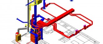
- An axonometric diagram is drawn up listing all the elements.
- Based on the diagram, the length of the channels is calculated.
- The flow rate in each section is determined. Each individual section has a single cross-section of air ducts.
- After this, calculations are made of the speed of air movement and pressure in each individual section of the system.
- Next, friction losses are calculated.
- Using the required coefficient, the pressure loss due to local resistance is calculated.
During the calculation process, at each section of the air distribution network, various data will be obtained that must be equalized with the branch of the greatest resistance using diaphragms.
Calculation method
Initially, it is necessary to calculate the required cross-sectional area of the air duct based on data on its flow rate.
- The cross-sectional area of the air duct is calculated using the formula
FP=LP/VT
Where
LP
– data on the movement of the required volume of air in a specific area.
VT
– recommended or permissible air speed in an air duct for a specific purpose.
- Having received the required data, a standard size of the air duct close to the calculated value is selected. Having new data, the real speed of gas movement in the ventilation system section is calculated using the formula:
VФ=LP/FF
Where
LP
– consumption of the gas mixture.
FF
– actual cross-sectional area of the selected air duct.
Similar calculations must be carried out for each individual ventilation section.
To correctly calculate the air speed in the duct, it is necessary to take into account friction losses and local resistance. One of the parameters influencing the amount of losses is friction resistance, which depends on the roughness of the air duct material. Data on the coefficient of friction can be found in reference literature.
Algorithm for calculating air speed
Taking into account the above conditions and the technical parameters of a particular room, it is possible to determine the characteristics of the ventilation system, as well as calculate the air speed in the pipes.
You should rely on the air exchange rate, which is the determining value for these calculations.
To clarify the flow parameters, the table is useful:
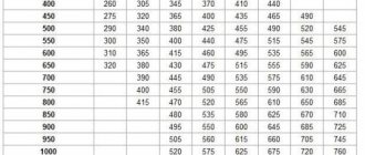
The table shows the dimensions of air ducts with a rectangular cross-section, that is, their length and width are indicated. For example, when using channels 200 mm x 200 mm at a speed of 5 m/s, the air flow will be 720 m³/h
To make your own calculations, you need to know the volume of the room and the rate of air exchange for a room or hall of a given type.
For example, you need to know the parameters for a studio with a kitchen with a total volume of 20 m³. Let's take the minimum multiplicity value for the kitchen - 6. It turns out that within 1 hour the air channels should move about L = 20 m³*6 = 120 m³.
It is also necessary to find out the cross-sectional area of the air ducts installed in the ventilation system. It is calculated using the following formula:
S = πr2 = π/4*D2
Where:
- S is the cross-sectional area of the air duct;
- π is the number “pi”, a mathematical constant equal to 3.14;
- r is the radius of the air duct section;
- D is the cross-sectional diameter of the air duct.
Let's assume that the diameter of the round duct is 400 mm, substitute it into the formula and get:
S = (3.14*0.4²)/4 = 0.1256 m²
Knowing the cross-sectional area and flow rate, we can calculate the speed. Formula for calculating air flow speed:
V = L/3600*S
Where:
- V —air flow velocity, (m/s);
- L — air flow, (m³/h);
- S – cross-sectional area of air channels (air ducts), (m²).
We substitute the known values, we get: V = 120/(3600*0.1256) = 0.265 m/s
Therefore, in order to ensure the required air exchange rate (120 m3/h) when using a round duct with a diameter of 400 mm, it will be necessary to install equipment that allows you to increase the air flow speed to 0.265 m/s.
It should be remembered that the previously described factors - parameters of the vibration level and noise level - directly depend on the speed of air movement.
If the noise exceeds the norm, you will have to reduce the speed, and therefore increase the cross-section of the air ducts. In some cases, it is enough to install pipes made of a different material or replace a curved channel fragment with a straight one.
Calculation of friction losses
First of all, you should take into account the shape of the air duct and the material from which it is made.
- For round products, the calculation formula looks like this:
Ptr = (x*l/d) * (v*v*y)/2g
Where
X
– table friction coefficient (depending on the material);
I
– length of the air duct;
D
– channel diameter;
V
– rate of gas movement in a certain section of the network;
Y
– density of transported gases (determined from tables);
G
– 9.8 m/s2
Important! If rectangular ducts are used in the air distribution system, then the diameter equivalent to the sides of the rectangle (air duct cross-section) must be substituted into the formula. Calculations can be made using the formula: deq = 2AB/(A + B). For translation, you can also use the table below.
- Local resistance losses are calculated using the formula:
z = Q* (v*v*y)/2g
Where
Q
— sum of loss coefficients due to local resistance;
V
— speed of air flow in the network section;
Y
– density of transported gases (determined from tables);
G
– 9.8 m/s2
Important! When building air distribution networks, a very important role is played by the correct choice of additional elements, which include: grilles, filters, valves, etc. These elements create resistance to the movement of air masses. When creating a project, you should also pay attention to the correct selection of equipment, because fan blades and the operation of dehumidifiers and humidifiers, in addition to resistance, create the greatest noise and resistance to air flows.
Having calculated the losses of the air distribution system, knowing the required parameters for the movement of gases in each section, you can proceed to the selection of ventilation equipment and installation of the system.
Setting up an existing ventilation system
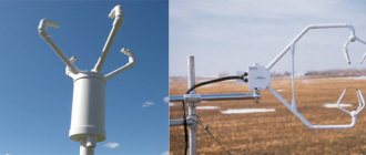
The main way to diagnose the operation of ventilation networks is to measure the air speed in the air duct, since knowing the diameter of the channels it is easy to calculate the actual flow of air masses. The devices that are used for this are called anemometers. Depending on the characteristics of the movement of air masses, the following are used:
- Mechanical devices with an impeller. Measurement limit 0.2 – 5 m/s;
- Cup anemometers measure air flow in the range of 1 – 20 m/s;
- Electronic thermal anemometers can be used to take measurements in any ventilation networks.
It’s worth looking at these devices in more detail. Electronic thermal anemometers do not require, as in the use of analogue devices, the organization of hatches in channels. All measurements are made by installing a sensor and receiving data on the screen built into the device. The measurement errors of such devices do not exceed 0.2%. Most modern models can operate both from batteries and from 220 v power supply. That is why professionals recommend using electronic anemometers for commissioning work.
As a conclusion: air flow speed, air flow and channel cross-sectional area are the most important parameters for the design of air distribution and ventilation networks.
Advice: In this article, as a clear example, the aerodynamic calculation method for a section of an air duct of a ventilation system was given. Carrying out computational operations is a rather complex process that requires knowledge and experience, and also takes into account a lot of nuances. Do not do the calculations yourself, but entrust it to professionals.
The importance of air exchange
Depending on the size of the room, the air exchange rate should be different.
The task of any ventilation is to ensure an optimal microclimate, humidity level and air temperature in the room. These indicators affect a person’s comfortable well-being during work and rest.
Poor ventilation leads to the proliferation of bacteria that cause respiratory tract infections. Food products begin to spoil quickly. Increased humidity levels provoke the appearance of fungus and mold on walls and furniture.
Fresh air can enter the room naturally, but compliance with all sanitary and hygienic indicators is possible only with a high-quality ventilation system. It must be calculated for each room separately, taking into account the composition and volume of air, design features.
For small private houses and apartments, it is enough to equip shafts with natural circulation of air flows. But for industrial premises and large houses, additional equipment is required in the form of fans that provide forced circulation.
When planning a building for an enterprise or public institution, the following factors must be taken into account:
- high-quality ventilation should be in every room;
- it is necessary that the composition of the air complies with all approved standards;
- enterprises require the installation of additional equipment that will regulate the air speed in the air duct;
- For the kitchen and bedroom it is necessary to install different types of ventilation.
In order for the air exchange system to meet all requirements, it is necessary to calculate the air speed in the air duct. This will help you choose the right device.
