Boiler operating map
Boiler operating chart - a document drawn up on the basis of operating and adjustment and balance sheets
tests, containing the main operational and control parameters of the boiler, the value
Efficiency, specific fuel consumption at different performance levels, etc.
A boiler regime map is required for its correct and competent operation.
The boiler regime map is drawn up again or adjusted every 3-5 years (link).
We draw up operating charts for any type of boilers and equipment.
Samples of boiler operating maps:
| our history | Boiler mode map SM | Regime card DKVR-10-13 | Regime card DKVR-20-13 | Viessmann mode card |
kotloman.ru
Boilers PTVM-50 and PTVM-100
Equipment of this type is designed in such a way that the location of the convective heating surface is above the firebox, which is insulated with 0.6x3 mm tubes with a pitch of 65 mm. The number of convective sections of the PTVM-100 boiler is 8, the PTVM-50 boiler has 4 sections. The convective flue is lined on both sides with 0.83 x 3.5 mm pipes, connecting to the frame frame from above through manifolds, and expands freely.
Oil-fired boilers can be equipped with a washing device - a gas-pulse cleaning device designed to clean deposits from the heating area and external contamination of pipes with fuel oil. Each burner is equipped with a blower fan. The pressure of fuel oil burners is 19-40 kgf/cm2, gas burner pressure is 0.2 kgf/cm2. For both types of boilers, lightweight lining is installed with fastening to screen pipes - thickness 110 cm or less.
Regime card
A regime map is drawn up for each boiler.
According to the regime map, the hot water and (or) steam boiler is operated.
The main function of the regime map is to display the required gas and air pressure at any (usually several points are specified) boiler load.
At the same time, the combustion process must be stable and as complete as possible, and the operation of the boiler must be efficient and safe.
A regime map is drawn up based on the results of measurements, calculations and thermal tests by those organizations that carry out commissioning work. Such tests are carried out once every 3 years.
The regime map is executed both in the form of a table and in the form of a graph. If this is a table, then several operating modes are usually specified: 30, 50, 70, 100 percent of the boiler productivity.
An example of a steam boiler operating map (pictures are clickable).
A photo of a real map, not very high quality, but you can see the meaning.
And an example of measurements during testing
foraenergy.ru
Ministry of Education and Science of the Russian Federation
FEDERAL STATE BUDGET EDUCATIONAL INSTITUTION OF HIGHER PROFESSIONAL EDUCATION
"TYUMEN STATE OIL AND GAS UNIVERSITY"
INSTITUTE OF INDUSTRIAL TECHNOLOGY AND ENGINEERING
Guidelines
for practical work
in the discipline "Operation and adjustment
heating equipment"
specialty 140102.51 Heat supply and heating equipment
Tyumen 2012
Content:
| No. practical work | Work theme | Page |
| 1 | Studying the boiler operating map | 3 |
| 2 | Studying the procedure for accepting and handing over a shift | 7 |
| 3 | Studying the sequence of operations when starting and stopping the gas distribution unit (GRU) | 11 |
| 4 | “Studying the sequence of operations when switching to bypass” | 20 |
| 5 | “Studying the sequence of operations when starting a boiler” | 25 |
| 6 | “Studying the sequence of operations when stopping the boiler” | 29 |
| 7 | “Studying the sequence of operations when transferring from one type of fuel to another (reserve)” | 33 |
| 8 | “Studying instructions for boiler room personnel and other regulatory documentation” | 43 |
| 9 | “Start-up, maintenance during operation and shutdown of a steam pipeline, water heating network.” | 50 |
Practical work 1. “Study of the boiler operating map”
Purpose of the work: to study the boiler operating map.
The student must:
know:
— structure of the enterprise’s energy department;
— functional responsibilities of officials and maintenance personnel of the power plant;
— content of the main regulatory documents regulating the operation of heating equipment and heating networks;
be able to:
- use the main document that determines the operating conditions of the boiler - the regime map.
General information
Boiler operating map.
Each boiler must have its own regime map.
The operation of a steam or hot water gas boiler must be carried out in accordance with its operating schedule.
The purpose of the regime map is to show the required gas and air pressure at a certain boiler load. In this case, the combustion process must be as complete and stable as possible, and the operation of the boiler must be efficient and safe.
The regime map is compiled based on the results of thermal technical tests by the organization carrying out commissioning work. Tests are carried out once every three years.
The regime map can be made in the form of a table or graph. In the case of a table, several operating modes are set in it: 30%, 50%, 70%, 100% of the boiler output.
Example of a boiler operation map
| Measured parameter | 30% | 50% | 70% | 100% |
| Steam capacity t/hour | 2,1 | 5,6 | 13,2 | 18,5 |
| Gas pressure at burners kPa | 1,5 | 2 | 3 | 4 |
| Air pressure at burners kPa | 0,1 | 0,7 | 1,2 | 1,5 |
| Gas content behind the boiler % | ||||
| CO2 | 6,5% | 4,3% | 2,4% | 1,9% |
| O2 | 1,2% | 0,5% | 0% | 0% |
| CO | 0% | 0% | 0% | 0% |
| Exhaust gas temperature | 103 | 112 | 119 | 129 |
| Heat loss with flue gases % | 5,3 | 5,6 | 6,1 | 6,7 |
| Heat loss from chemical underburning % | 0 | 0 | 0 | 0 |
| Heat loss to the environment % | 2,2 | 1,4 | 0,5 | 0,3 |
| Gross efficiency % | 86,6 | 87,5 | 92,1 | 86,3 |
| Net efficiency % | 83,2 | 85,1 | 88,3 | 87,2 |
There should be a duplicate of the regime card near each boiler. It must bear a signature from the organization that carried out the commissioning work.
The boiler operating mode must strictly comply with the operating schedule drawn up on the basis of equipment testing and operating instructions. In case of reconstruction of the boiler and change in the brand and quality of fuel, the regime map must be adjusted.
The regime map is a guide for maintenance personnel on maintaining the operating mode of the boiler and auxiliary equipment. It is compiled based on the results of operational adjustment or balance tests of the boiler. If a power plant has several boilers of the same type running on the same fuel, the full tests can be carried out on one of these boilers. For the remaining boilers of this series, based on the results of several experiments, the necessary clarifications are made to the regime map.
Operational and adjustment tests of a newly commissioned boiler are carried out immediately after the completion of the initial adjustment of the mode. During the initial commissioning period, maintenance personnel are issued temporary operating instructions. The regime map requires replacement or adjustment when switching to burning a new type or brand of fuel, after reconstruction of the combustion chamber, changing the layout of the heating surfaces. Separate adjustments are made to the regime map after carrying out such repair work as sealing the furnace and gas ducts, replacing cubes or packing of air heaters, installing additional means for cleaning heating surfaces, replacing or surfacing worn smoke exhaust blades, etc.
The regime map is compiled for thermal loads covering the full range of permissible boiler loads. It must indicate the values of the main parameters of the boiler: temperature of feed water, fresh steam and reheating steam, steam before injection, flue gases, fuel oil heating for fuel oil boilers, air in front of the air heater for sulfur and wet fuels and pressure in the primary air box for pulverized coal boilers .
One of the main indicators characterizing the operating mode of the boiler is the excess air in the combustion products, therefore, in the regime map for each boiler load, the value of the oxygen or carbon dioxide content in the flue gases behind the superheater must be indicated. In addition, the regime map provides instructions on the number and operating mode of burners or nozzles, fuel consumption (on gas-oil boilers), the number and load of draft machines included in the operation. It is advisable to include in the regime map some indicators that make it easier to maintain the optimal regime, for example, the temperature of the gases in the turning chamber, the air pressure behind the air heater, the resistance of the air heater, the air flow to the mills, etc.
The regime map indicates for what operating conditions of the boiler it was compiled (the main characteristics of the fuel, the presence of flame illumination with fuel oil or gas, re-cleaning of heating surfaces, the position of the regulators on the air ducts in front of the burners and on the gas recirculation lines, etc.).
For dust preparation systems with an intermediate dust bin, a separate regime map is drawn up, which indicates the optimal parameters of the dust preparation system (mill ball loading, fineness and moisture content of the dust, vacuum in front of the mill, its aerodynamic resistance, temperature of the drying agent behind the mill, ventilation air flow and mill fan loading ). The main operating parameters of mill systems in direct injection schemes are also entered into the boiler operating map. The settings of the automatic control system of the boiler must comply with the instructions of the regime map.
Questions:
1. Based on what tests is the regime map drawn up?
2.When the mode card requires replacement or adjustment
3.For what heat loads is the boiler operating schedule drawn up?
4.What are the main values of the boiler parameters indicated in the regime map?
5.What should the settings of the boiler automatic control system correspond to?
Bibliography:
- “Rules for technical operation of thermal power plants” clause 5.3. Steam and water heating plants
- “Guidelines for the development of instructions and regime maps for the operation of pre-boiler water treatment plants and for maintaining the water chemistry regime of steam and hot water boilers”
- p 4, 5, 6
- https://www.energosovet.ru/bul_stat.php?idd=1
- https://www.stroi-blok.ru/?p=380
- https://www.docload.ru/Basesdoc/8/8090/index.htm
Practical work 2. “Studying the procedure for accepting and handing over a shift.”
Purpose of the work: to study the procedure for accepting and handing over shifts at the OJSC Heat Supply Enterprise boiler house.
The student must:
know:
— rules for registration, technical examination and permission to operate boilers and heating networks;
— basic guiding regulatory materials and documents regulating the design and safe operation of heating equipment, heating networks, and fuel facilities;
— operational characteristics of heating equipment;
— control and accounting of the operation of energy shop equipment, documents on accounting and reporting;
be able to:
— determine the objects of heating equipment and their technical characteristics in respect of which these Rules apply;
— determine standards of maintenance and operation for specific machines and units of heat supply systems and heating networks;
-accept and hand over a shift;
-monitor the operation of equipment and devices.
General information
To accept a shift, a worker (specialist) must report to work in advance, familiarize himself with the entries in the log and daily reports, with all orders relating to the boiler equipment he serves from the time of his previous duty, as well as with changes in the operation of the equipment, malfunctions and malfunctions.
The worker (specialist) handing over the shift is obliged to familiarize the person on duty with the condition and operating mode of the equipment handed over to him, the boiler load schedules and inform him what equipment is in reserve and under repair, what repair work has been carried out and should be carried out.
The worker (specialist) taking over the shift must check:
1) water level in steam boilers (by opening test taps and purging water indicating devices) and the presence of water in the heating system (via the signal tube);
2) steam pressure as measured by the pressure gauge and the serviceability of the pressure gauge itself;
3) the temperature of superheated steam and flue gases behind the boiler;
4) reliability of operation of safety valves (by blowing) and water seal;
5) the condition of the boiler (are there any bulges, cracks, leaks) and its lining, steam superheaters, water economizers, air heaters, combustion devices, fans and smoke exhausters;
6) serviceability of feed and circulation pumps by briefly putting them into operation;
7) availability of the necessary supply of water in feed tanks;
 the presence of seals on pressure gauges and the control and safety valve casing;
9) absence of slag and ash in the bunkers of the furnace and flues;
10) compliance of the position of all steam, water and gas valves (gates) and taps with the normal operating scheme;
11) tightness of closing of drain and purge valves;
12) position of dampers on hogs and dampers on the air duct;
13) the state of automatic safety and automatic control systems;
14) serviceability of lighting fixtures, emergency lighting, stairs, passages, work platforms, communication equipment and alarms from the fireman’s workplace, laundering tools; availability of guarded drive belts and couplings, portable lighting fixtures and fire-fighting equipment;
15) time of the last blowdowns and blowdowns of boilers, steam superheaters, water economizers and air heaters (according to the log);
16) operation of gas burners (in a gasified boiler room), paying special attention to the gas and air pressure in front of them; flame stability, completeness of gas combustion (according to gas analyzer readings, flame color, draft force in the furnace and temperature of gases leaving the chimney);
17) the condition and position of taps and valves on the gas pipeline, both for operating boilers and those in reserve and repair (paying attention to the absence of gas leaks);
18) condition of the hydraulic fracturing or gas distribution unit equipment; serviceability of the lining of the firebox dividers, boiler casing, and safety explosion valves; availability of necessary ventilation of the gasified room, operability of fans for supplying air to the burners; is there a gas leak, etc.;
19) operation of fuel oil nozzles;
20) the condition and operation of fans for supplying air to nozzles and ventilation systems, as well as smoke exhausters, paying attention to the presence of noise and knocking during their operation and overheating of the bearings;
21) the condition of the walls of the combustion chambers and boiler walls that are under the direct influence of the torch and flue gases, where burnouts, vents, cracks, leaks or some other visible damage can most often occur.
In the event of an emergency condition, slagging and contamination of the equipment, the worker (specialist) handing over the shift must stay until the defects are eliminated.
After making sure that all equipment is in full working order, the worker (specialist) must sign the logbook. If malfunctions are discovered during the inspection, the worker (specialist) taking over the shift is obliged to notify the person in charge of the boiler room and subsequently act according to his instructions.
The worker (specialist) accepting the shift must remember that he is responsible for malfunctions and unsatisfactory condition of the equipment that arose in the previous shift and were not recorded during acceptance.
Questions:
1. Allowed to service boiler installations are...
2. Operating personnel must know and follow the instructions: ….
3. How is the acceptance and delivery of a shift processed?
4. What is written in the logbook
5. Who is responsible for equipment malfunctions
Bibliography:
- “Rules of the Gosgortekhnadzor of Russia for the design and safe operation of steam, water-heating boilers and heating networks”
- “Standard instructions on labor protection for boiler room operator” RD.34.03.233-93.UDK 658.382.3:621.182
- “Standard instructions for safe work performance for boiler room personnel” clause 8
- https://www.nchkz.ru/lib/41/41798/index.htm
Practical work 3. “Studying the sequence of operations when starting and stopping the gas distribution unit (GRU).”
Place of work: OJSC Heat Supply Enterprise.
Purpose of the work: to study the sequence of operations when starting and stopping a gas distribution installation (gas distribution point)
The student must:
know:
— design of solid fuel supply systems, dust preparation systems, basic rules for their operation;
— devices and operating rules for fuel oil supply and gas supply systems for boiler houses;
be able to:
— carry out start-up, shutdown and maintenance of equipment for fuel supply systems of boiler houses.
General information
Gas distribution installation (station) is a set of technological equipment that provides pressure reduction, cleaning and accounting of gas flow before supplying it to the gas distribution network.
Gas distribution installations provide gas supply from main gas pipelines and branches to populated areas, industrial and agricultural enterprises in a given quantity. The gas distribution unit is designed for operation outdoors in areas with seismicity up to 8 points in a temperate climate at temperatures from -400 to +500C and in cold climates at temperatures from -600 to +500C, which makes the gas distribution unit universal and independent of fluctuations in external temperature environment.
Main functions of the gas distribution plant:
- gas distribution installation is the reduction of high pressure gas to a specified low pressure and maintaining it with a certain accuracy;
- gas distribution installation is heating of gas before reduction;
- gas distribution installation is an automatic mode control. Gas distribution installation is the work of the station’s process equipment, including limiting gas supplies according to the requirements of the gas distribution organization (GDO);
- gas distribution installation is the issuance of emergency and warning signals in case of malfunctions to the control panel to the dispatcher or operator;
- gas distribution installation is a measurement of gas consumption with multi-day data recording and transfer of information to the level of the gas distribution organization;
- gas distribution plant - gas odorization;
- gas distribution unit - purification of gas from droplets of moisture and mechanical impurities;
- For each gas distribution unit (GRU), a passport is drawn up containing the main characteristics of the equipment, measuring instruments and premises. Technological diagrams, operating instructions, safety and fire safety instructions are posted at the State Distribution Unit (GRU);
- When operating the hydraulic fracturing unit (GRU), they perform maintenance, current and major repairs. The results of inspections (repairs) of equipment associated with the replacement of parts and components of equipment are entered into the passport of the State Register Office (GRU). All other work is recorded in the operational log, which also indicates violations of the normal operation of the equipment and measures taken to eliminate malfunctions;
- the settings of the hydraulic fracturing equipment (GRU) are set by the chief engineer of the gas enterprise for household consumers or the person responsible for the gas industry of gas consuming enterprises;
- at the same time, the maximum operating gas pressure after the regulator for household consumers should not exceed 300 daPa for natural gas pipelines. Safety relief valves, including those built into pressure regulators, must ensure gas relief when the maximum operating pressure after the regulator is exceeded by no more than 15%. The upper limit of operation of safety shut-off valves should not exceed 25% of the maximum operating gas pressure after the regulator. Gas pressure fluctuations at the outlet of the hydraulic fracturing unit (GRU) are not allowed to exceed 10% of the operating pressure. Malfunctions of regulators that cause an increase or decrease in operating pressure, malfunctions in the operation of safety valves, as well as gas leaks must be repaired immediately as an emergency;
- shut-off devices on the bypass line and in front of the relief safety valve must be sealed;
- gas supply through the bypass line is allowed only for the time necessary to repair equipment and fittings, or during the period of reducing the gas pressure before the hydraulic fracturing (GRU) to a value that does not ensure reliable operation of the pressure regulators.
studfiles.net
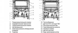
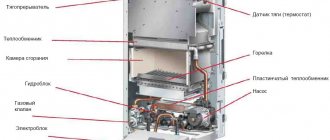
Design and installation of the TVG 8M boiler
On the front wall of the boiler there are inspection holes through which the furnace cavity is inspected. During normal operation of the heater, the channels are filled with bricks that are not connected to the main wall.
The rear wall contains 2 valves, which are destroyed in the event of a possible explosion of a mixture of gas and oxygen in the firebox. The resulting gases squeeze out the safety elements and escape into the atmosphere; the boiler lining remains monolithic.
The design of the combustion screen manifolds includes drain lines that allow water to be removed from the heating circuit during repair or maintenance of the boiler. The drainage channels are equipped with manually operated taps.
To remove air pockets, a special purge system equipped with tubes and valves is used. Normal water circulation and heating to the set temperature are ensured only after gases are removed from the lines.
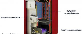
The external lining of the TVG 8M water heating installation consists of an internal part lined with fireclay-type firebricks. On the outside there is a second layer made of standard red brick. The design forms combustion chambers in which heating circuits are mounted.
Hot gases wash the surfaces of the pipes, providing an increase in water temperature with reduced heat loss to the environment. The plant declares efficiency at 90.2%; due to modernization (for example, replacing burners), the parameter reaches 95-96%.
How is documentation for the boiler prepared?
Each technical equipment requires serious and careful treatment. This becomes possible thanks to the skillful and professional use of instructions and various types of application manuals supplied with this or that equipment. That is why, as soon as you purchase something new, do not under any circumstances throw away everything that is included with your telephone, refrigerator, gas equipment, and even an iron and electric kettle. The fact is that even if you yourself are not able to cope with the procedures that are described there, they may be required by the specialists whom you hire to repair this or that equipment. Particular care must be taken when handling equipment that has a long service life and is not intended to be written off after a short period of use. Such equipment includes refrigerators, washing machines and, of course, gas boilers. The documents related to the last mentioned technical devices include the boiler operating map.
According to the principle of operation, boilers are classical and pyrolysis (gas generator).
Thanks to this documentation, the correct and uninterrupted operation of gas and water heating equipment is ensured. Its form is generally accepted and uniform. It was installed back in the Soviet Union, in 1984 by Glavgosgaznadzor.
Hot water boiler operating map table.
Most of the indicators located in a particular map are measured in percentages and allow you to measure the following:
- the amount of gas is located behind the boiler;
- percentage of heat loss that goes away with the burned gas;
- the amount of heat released during the operation of the heaters;
- the amount of heat lost as a result of chemical underburning;
- boiler efficiency (net and gross);
- percentage of gases such as oxygen, carbon and carbon monoxide.
Other values in the boiler operating charts:
- gas pressure;
- air pressure on burners;
- the number of vapors formed over a certain time;
- their outlet temperature.
All quantities are measured in appropriate units: degrees, kiloPascals, etc.
All boilers have their own mode maps.
They serve to ensure that with their help the most correct and efficient operation of both steam and gas and even water heating equipment is carried out.
The most basic quality of this map, which ensures the above-mentioned state of the boiler, is that it allows you to observe all the changes that occur during the operation of the equipment. For example, it displays how much gas or air pressure is needed for a particular load on the boiler. With all this, the safe operation of this equipment must also be ensured, as well as a complete and stable combustion process.
Return to contents
Table of test measurements.
In order for this document to be created, it is necessary to carry out a sufficiently large number of measurements and experiments (at the stage of production and commissioning of boilers). For this purpose, organizations specializing in commissioning carry out thermal testing. This is done every 3 years, and all sorts of calculations and measurements are also carried out here. Most often, a regime map looks like an ordinary table, which can be designed with a minimum of two columns, and a maximum of five. It depends on what operating modes are implied when operating the equipment. There are 4 of them in total: 100, 70, 50 and 30 percent modes. As for the number of lines, there are much more of them, since each of them individually indicates the parameters that were indicated above (their unit of measurement is indicated next to them in the first column; there is no separate column for them). Another option for designing a regime map is a schedule, but it is used much less frequently.
The map is usually produced in several (usually two) copies, one of which should be placed next to the cauldron, some even glue it to the cauldron. But if you are afraid for its safety, then make several additional copies yourself. In order for you to completely trust the data indicated on the card, the company that carried out the commissioning work puts a signature or brand name on it (or on the boiler itself).
In addition to the main indicators, the map also shows indicators of the dependence of gas pressure on boiler performance, as well as how much air pressure depends on gas pressure. These indicators become necessary so that you (or a master adjuster) can ensure the adjustment of a gas or water heating boiler both with accurate indicators on the map and with intermediate loads on it.
Return to contents
There is another option for designing a boiler regime map. It is used when it is equipped with a horizontal slot burner (injection). Here, instead of such an indicator as air pressure, the location of some devices is indicated. These include those parts that regulate the air supply: the gaps of the curtains on the blower sheet and the air control damper. In addition to them, it can be indicated how the profile dampers are located in it and the air proportioner on the bypass window.
In addition to some general regime maps, economizer maps are compiled. This is done when economizers are tested. After this, you will also need a summary statement, which reflects the results of absolutely all calculations and measurements. For the most complete description of the technical characteristics and capabilities of the boiler, as well as so that during adjustment or repair you can fully understand the proposed process, a full technical report is created. It depends on exactly what measurements and calculations (or some other additional measures) were performed. For equipment that was made in a new configuration (in other words, for converted boilers), it is necessary to evaluate in the reports how well the work done corresponds to the goals of the modernization and the entire project as a whole. Here it would be useful to analyze all the measures taken.
So, drawing up a regime map is necessary for the full and high-quality operation of various types of gas, water heating and even steam equipment. It should, if possible, be located close to the boiler so that you do not confuse any indicators and damage the unit.
1poteply.ru
Specifications
Primary air is supplied to the burner of the TVG-8 boiler by a Ts-13/50 blower fan for the TVG boiler, modification 5, with an air capacity of 13,000 m3/h. Air flow adjustment is carried out by the M30 actuator, working with the safety regulator R-25.3.2.
The M30 mechanism closes/opens the axial guide vane built into the air duct in front of the suction diffuser of the blower fan. The guide vane is controlled by the boiler operator remotely from the control panel or automatically by the boiler control system.
Flue gases move through smoke exhaust channels, through the firebox and economizer, thanks to the vacuum created by the D-18 smoke exhauster.
The operation of the smoke exhauster is controlled similarly to the operation of the fan through the actuator and vacuum regulator P25.1.2 installed on the boiler control panel.
Main technical parameters of the TVG 8 hot water boiler:
- thermal power - 8.63 Gcal/hour;
- radiation heating surface - 76.0 m2;
- convective heating surface - 109.6 m2;
- temperature graph of network water - 150/70 C;
- water volume of the unit - 4.0 m3;
- maximum coolant flow through the boiler unit is 104.0 m3/hour;
- exhaust gas temperature at the boiler outlet - 180C;
- hourly gas fuel consumption - 1100 m3/hour;
- pressure in the supply network - 14.0/8 atm;
- The efficiency of the boiler unit is 90%.
When purchasing a unit, the manufacturer provides the owner with detailed drawings of the boilers, all technical documentation, an equipment passport and factory instructions, which contain sections on the design of the TVG boiler, the procedure for installation, commissioning, operation, maintenance and repair.