4.1. Heat output scale for hot water boilers
The purpose of hot water boilers is to obtain hot water of specified parameters for heat supply to heating systems of household and technological consumers.
The industry produces a wide range of water heating boilers that are standardized in design. The characteristics of their operation are heat output (power), temperature and water pressure, and the type of metal from which hot water boilers are made is also important. Cast iron boilers are available for heating capacity1 to 1.5 Gcal/h, pressure 0.7 MPa and hot water temperature up to 115 °C. Steel boilers are manufactured in accordance with the heat output scale of 4; 6.5; 10; 20, 30; 50; 100; 180 Gcal/h (4.7; 7.5; 11.7; 23.4; 35; 58.5; 117 and 21.0 MW). Hot water boilers with a heating capacity of up to 30 Gcal/h usually provide operation only in the main mode with water heating up to 150 °C with a water pressure at the boiler inlet of 1.6 MPa. For boilers with a heating capacity above 30 Gcal/h, it is possible to operate in both main and peak modes with water heating up to 200 °C with a maximum pressure at the boiler inlet of 2.5 MPa.
4.2. Cast iron sectional hot water boilers
Cast iron sectional water heating boilers have a low heating output and are mainly used in water heating systems of individual residential and public buildings. Boilers of this type are designed to heat water to a temperature of 115 °C at a pressure of 0.7 MPa. In some cases, cast iron boilers are used to produce water steam; for this purpose they are equipped with steam collectors.
Of the large number of different designs of cast iron sectional boilers for industrial production, the most widely used boilers are the types “Universal”, “Tula”, “Energia”, “Minsk”, “Strelya”, “Strebelya”, “NRch”, KCh and a number of others.
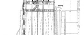
Rice. 4.1. Cast iron sectional hot water boiler "Energia-3" :
1 - boiler section; 2 - steel rope; 3, 10 - pipes for water inlet and outlet; 4 - gate; 5 - chimney; 6 — grate; 7 - air duct; 8 - door; 9 - counterweight
The production of most of these types of boilers ceased about 30 years ago, but they will still be in operation for quite a long time. In this regard, as an example, let us consider the design of a cast-iron sectional water heating boiler “Energia-3”. The boiler is assembled from separate sections (Fig. 4.1), connected to each other using liners - nipples, which are inserted into special holes and tightened with coupling bolts. This design allows you to create the required heating surface of the boiler, as well as replace individual sections in case of damage.
Water enters the boiler through the lower pipe, rises up through the internal channels of the section, heats up and leaves the boiler through the upper pipe. Fuel is supplied to the firebox through the door opening. The air required for combustion enters under the grate through air duct 7. Combustion products formed during fuel combustion ( GHGs) move upward, then the direction of GHG flow changes by 180°, i.e. the G1G flow moves down the brick channels and is then directed through a common collection chimney into the chimney.
When moving, the steam generators are cooled, their heat is transferred to the water located inside the sections. In this way, the water is heated 66 to the required temperature. The draft in the boiler is regulated by a gate connected by a steel rope through a block with a counterweight. The rated power of the Energia-3 water heating boilers is 0.35... 0.69 MW, efficiency 73%.
4.3. TVG series hot water boilers
Cogeneration water heating boilers of the TVG series are produced with a heating capacity of 4 and 8 Gcal/h (4.7 and 9.4 MW). These sectional welded boilers are designed to operate on gas with water heating not exceeding 150 °C.
Rice. 4.2. Water heating boiler TVG-8 : a - water circulation diagram; o - boiler design; 1, 2 - lower and upper collectors of the convective surface, respectively; 3, 5 — ceiling-front pipes; 4, 6 - lower and upper collectors of the ceiling screen; 7 — left side screen; 8, 14 — two-light screens; 9 — right side screen; 10 - water outlet to the heating network; 11 — convective heating surface; 12 — radiation surface of the furnace; 13 — air channel; 15 — burners; 16 - sub-pod channels
In the TVG-8 water heating boiler, the radiation surface of the furnace 72 (Fig. 4.2) and the convective heating surface 77 consist of separate sections made of pipes with a diameter of 51 * 2.5 mm. In this case, in sections of the convective surface the pipes are located horizontally, and in sections of the radiation surface - vertically. The radiation surface consists of a front-ceiling screen and five sections of screens, three of which are double irradiated (two-light screens 8 and
The boiler is equipped with hearth burners 75, which are located between the sections of the radiation surface. Air from the fan enters the air channel from which it is supplied to the sub-channels connected to the burners. The fuel combustion products move along the pipes of the radiation surface, pass through the window in the rear part of the furnace and enter the lower shaft, washing the convective surface with a transverse flow. At the same time, water for heating enters the two lower collectors 7 of the convective surface and is collected in the upper collectors of the convective surface. Next, through several ceiling-front pipes, water is directed to the lower collector of the ceiling screen, from where it flows through the ceiling-front pipes to the upper collector of this (ceiling) screen. After this, the water sequentially passes through the pipes of the screens: the left side 7, three two-light and the right side. The heated water through the collector of the right side screen enters the outlet into the heating network.
Water heating boilers of the TV G series have an efficiency of 91.5%.
Rating of the best gas boiler manufacturers
The reliability and stability of heating a private house or apartment depends on the operation of thermal equipment. Saving in its selection is impractical.
Among manufacturers producing boilers, the following brands are popular with consumers:
- Buderus is a company of German origin that produces reliable wall and floor models. There are devices with cast iron heat exchangers. The product line includes devices with open and closed burner.
- Navien is a Korean manufacturer with official representative offices in Russia, the USA and other countries. The products are famous for their unpretentiousness, low noise level, and reliability in operation. Navien boilers are distinguished by their low gas pressure requirements.
- Bosch - a company from Germany is famous for the reliability of its equipment. The manufacturer produces a full range of gas equipment for domestic use. The boilers are distinguished by increased operational safety and convenient control.
- Vaillant is a German brand popular in the gas equipment market. The company produces boilers with a closed and open combustion chamber with a power from 4 to 240 kW. The products are equipped with a reliable safety system, including protection against freezing, overheating and pump blocking. There is a wide network of service centers throughout Russia.
- Viessmann is a manufacturer that produces reliable heating and water heating equipment. The line of gas boilers includes single- and double-circuit models for floor and wall installation. The devices are environmentally friendly and have low noise levels. There is built-in protection against power surges. Many models can use both natural and liquefied gas as fuel.
- Ariston is an Italian brand, along with household appliances, offering gas equipment for heating and hot water supply. The boilers are famous for their high efficiency and low energy consumption. The devices are equipped with pump stop protection, flame modulation, and a semi-automatic ignition system. Thanks to the stylish design, the equipment looks good in the interior.
- Baxi is a company from Italy that produces water heating and heating equipment. The product line includes convection and condensing boilers of different capacities and designs. They are equipped with a good system for ensuring safe operation. There is a flame modulation mode that helps reduce fuel consumption. Built-in automation responds to changing weather conditions.
- Lemax is a Russian brand that produces reliable, inexpensive installations using components from foreign manufacturers. Models available for floor and wall installation. The devices are adapted for Russian conditions: they can be operated at low gas pressure, and the voltage range has been expanded. Composite materials are used in manufacturing. A wide network of service centers allows you to quickly resolve any problems that arise.
- ZhMZ - products of the Zhukovsky Machine-Building Plant are popular in the budget segment of the market. The devices have a full range of basic functions and are well adapted to work in Russian conditions. There is gas pressure control, non-volatile ignition, and overheating protection. German-made automation is used. The devices are designed to operate on natural and liquefied gas.
- Neva is a Russian company from St. Petersburg that produces heating equipment of several modifications. Boilers with one and two circuits are available. The copper heat exchanger is highly efficient and resistant to temperature changes. The safety system includes protection against freezing, overheating, and pump blocking. The auto-diagnosis function allows you to quickly identify malfunctions in the installation.
By choosing a boiler manufactured by one of the manufacturers listed above, you can be sure of its long-term reliable operation.
4.4. Steel hot water boilers of the KV-TSi series KV-TSV
Hot water boilers of the KV-TS series with a layered method of burning solid fuel are produced with a heating capacity of 4; 6.5; 10; 20; thirty; 50 Gcal/h (4.7; 7.5; 11.7; 23.4; 35 and 58.5 MW). Boilers of this series are intended for installation at thermal power plants, in industrial heating and heating boiler houses. Water heating boilers of the KV-TSV series differ from boilers of the KV-TS series only in the presence of an air heater.
All hot water boilers of both these series have combustion screens made of pipes with a diameter of 60 x 3 mm. Convective bags in them are made from pipes with a diameter of 28 x 3 mm. The boilers are equipped with chain return grates with pneumomechanical fuel throwers.
Hot water boilers KV-TS-4 and -6.5 have a convective shaft (Fig. 4.3) with a heating surface and a combustion chamber
Rice. 4.3. Water heating boilers KV-TS-4 and -6.5 :
1 - window for the exit of combustion products from the combustion chamber; 2 - convective shaft with heating surface; 3 - nozzle for returning fuel carryover to the chain grid; 4 - slag bunker; 5 - reverse chain grille; 6 — pneumomechanical fuel thrower; 7 — fuel bunker; 8 - combustion chamber
camera; GHG - combustion products
Fuel (coal) from the hopper 7 is supplied to the return chain grid 5 by means of a pneumo-mechanical spreader. Air for fuel combustion is supplied by a fan into the ducts, through which it is sectioned and supplied under the chain grate. The fuel combustion products from the combustion chamber enter the convective shaft through the upper openings in the rear wall of the combustion chamber (windows). The heat of the GHG is perceived by convective heating surfaces in convective shaft 2, and cooled GHGs are removed from the boiler through a gas duct located in the lower part of the convective shaft. With the GHG flow Fuel is partially carried away from the combustion chamber; to catch it, a special fan is installed in the convection shaft bunker, which returns the carried away fuel through the nozzles to the combustion chamber onto the chain grate.
equipped with chain return grids 7 of different lengths and two pneumomechanical fuel throwers. In the rear part of the combustion chamber there is an intermediate shielded wall 6, forming an afterburning chamber. The screens of the intermediate wall are made of two rows. The side walls of the combustion chamber, as well as the convection shaft, have lightweight lining. The front wall of the combustion chamber is not shielded and has heavy lining.
The front and rear walls of the convection shaft are shielded. The front wall of the convective shaft, which is also the rear wall of the combustion chamber, is made in the form of an all-welded screen, turning into a four-row scallop at the bottom. The side walls of the convective shaft are closed with vertical screens made of pipes with a diameter of 83 3.5 mm.
Combustion products enter the convective shaft from below and pass through the festoon. The shaft contains packages of convective heating surfaces made in the form of horizontal screens. Collected fines and unburned fuel particles are collected in ash bins under the convective shaft and, through the entrainment return system, are thrown into the combustion chamber through pipeline 5. In the front part of the return chain grate 7 there is a slag hopper, where slag is dumped from the grate.
The supply of network water to the boiler is carried out through the lower collector of the left side screen, and the output of hot water is through the lower left collector of the convective shaft.
For burning wet brown coals, boilers of the KB-TS series can be supplied with air heaters that provide air heating to 200...220 °C.
The water heating boiler K.V-TS-50 has a screened combustion chamber (Fig. 4.5), a chain return grate to which fuel is supplied by four pneumo-mechanical throwers. The rear screen of the combustion chamber at the entrance to the rotary chamber is opened into a four-row festoon. The walls and slopes of the rotary chamber, and Also, the rear wall of the convective shaft is shielded with pipes with a diameter of 60 x 3 mm. Convective heating surfaces are made in the form of U-shaped screens made of pipes with a diameter of 28 x 3 mm, which are welded to vertical pipes with a diameter of 83 x 3.5 mm, forming screens for the side walls of the convective shaft.
Behind the boiler there is a two-pass tubular air heater in the form of two cubes made of pipes with a diameter of 40 x 1.5 mm. The boiler is equipped with a fan 7 and devices for returning fuel carryover from the ash bins under the convective shaft and under the air heater to the grate. Secondary sharp blast is carried out through nozzles located on the rear wall of the firebox using a fan. The slag produced by burning fuel is dumped into the mine. To clean convective heating surfaces, a shot cleaning device is provided (shot cleaning unit 5).
Design
Double-drum vertical water-tube boilers are made according to the “D” design scheme, a characteristic feature of which is the lateral location of the combustion chamber relative to the convective part of the boiler.
Compound
The main components of the boilers are the upper and lower drums, the convection beam and the left combustion screen (gas-tight partition), the right and rear combustion screens that form the combustion chamber, as well as the screening pipes for the front wall of the firebox.
In all standard sizes of boilers, the internal diameter of the upper and lower drums is 1000 mm. The length of the cylindrical part of the drums increases with increasing boiler steam production from 2250 mm for 4 t/h boilers to 7500 mm for 25 t/h boilers. The distance between the drum axes is 2750 mm.
Materials
The drums are made of sheet steel grade 16GS GOST5520-79 with a thickness of 13 and 22 mm for boilers with an operating absolute pressure of 1.4 and 2.4 MPa (14 and 24 kgf/cm2), respectively.
For access to the inside of the drums, there are manholes in the front and rear bottoms.
Characteristics of convective beams
The convective beam is formed by vertical pipes Ø51x2.5 mm located along the entire length of the cylindrical part of the drums, connected to the upper and lower drums.
The width of the convective beam is 1000 mm for boilers with a steam capacity of 10; 25 t/h and 890 mm - for other boilers.
The longitudinal pitch of the convective bundle pipes is 90 mm, the transverse pitch is 110 mm (except for the average pitch located along the axis of the drums, equal to 120 mm). The pipes of the outer row of the convective bundle are installed with a longitudinal pitch of 55 mm; When entering the drums, the pipes are separated into two rows of holes.
In convective bundles of boilers 4; 6.5 and 10 t/h, longitudinal cast iron or stepped steel partitions are installed. Boilers 16 and 25 t/h do not have partitions in the bundle.
The convective beam is separated from the combustion chamber by a gas-tight partition (left combustion screen), in the rear part of which there is a window for gases to enter the beam.
The pipes of the gas-tight partition, the right side screen, which also forms under the ceiling of the combustion chamber, and the pipes of the front wall screening are inserted directly into the upper and lower drums.
Combustion chamber
The cross-section of the combustion chamber is the same for all boilers. Its average height is 2400 mm, width - 1790 mm. The depth of the combustion chamber increases with increasing boiler steam production from 1930 mm for DE - 4 t/h to 6960 mm for DE - 25 t/h.
| Factory designation of boiler | Steam productivity, t/h | Boiler operating pressure MPa (kgf/cm2) | State or temperature of steam, °C | Total heating surface, m2 | Boiler water volume, m3 | Boiler steam volume, m3 | Dimensions of the transportable unit | Boiler dimensions by boiler cell | Weight of transportable boiler block, kg | Boiler weight as supplied by the plant, kg | Type of gas and oil burner | Estimated fuel consumption for separate combustion | Accessories | |||||||
| length | width | height | length | width | height | economizer | fan | smoke exhauster | ||||||||||||
| Fuel oil, kg/h | Gas, m3/h | |||||||||||||||||||
| DE-4-14GM-O/R/ | 4 | 1,3 (13) | saturated | 67,9 | 4,2 | 1,05 | 3526 | 2970 | 4028 | 4200 | 9980 | 5050 | 11140 | 12250 | GM-2.5 | 273 | 291 | EB2-94I (BVES-1-2) | VDI-8-1000 | VDN-9-1000 |
| DE-4-14-225GM-O | overheated 225(+25;-10) | 73 | 4,6 | 1,2 | 11350 | 13898 | 282 | 301 | ||||||||||||
| DE-6.5-14GM-O/R/ | 6,5 | 1,3 (13) | saturated | 91,5 | 5,6 | 1,18 | 4276 | 4800 | 13015 | 13940 | GM-4.5 | 443 | 442 | EB2-142I (BVES-2-2) | VDN-9-1000 | VDN-11.2-1000 | ||||
| DE-6.5-14-225GM-O | overheated 225(+25;-10) | 101 | 5,4 | 1,3 | 13325 | 14380 | 457 | 488 | ||||||||||||
| DE-10-14GM-O/R/ | 10 | 1,3 (13) | saturated | 149 | 8,4 | 2,00 | 5706 | 3078 | 6530 | 16309 | 17721 | GM-7 | 673 | 718 | EB2-236I (BVES-3-2) | VDN-10-1000 | VDN-10-1500 | |||
| DE-10-14-225GM-O | overheated 225(+25;-10) | 156 | 2,10 | 6056 | 3202 | 16469 | 17841 | 695 | 742 | |||||||||||
| DE-10-24GM-O | 2,3 (23) | saturated | 149 | 2,00 | 5799 | 3078 | 4040 | 6579 | 18742 | 20412 | 673 | 718 | ||||||||
| DE-10-24-250GM-O | overheated 250(+25;-10) | 156 | 2,1 | 6084 | 3202 | 19045 | 20811 | 695 | 742 | |||||||||||
| DE-16-14GM-O/R/ | 16 | 1,3 (13) | saturated | 202,13 | 13,3 | 2,3 | 7460 | 3026 | 4032 | 8655 | 5205 | 6072 | 19290 | 21872 | GM-10 | 1087 | 1137 | EB2-330I (BVES-4-1) | VDN-9-1500 | VDN-11.2-1500 |
| DE-16-14-225GM-O | overheated 225(+25;-10) | 202 | 2,5 | 7822 | 19070 | 21935 | 1086 | 1144 | ||||||||||||
| DE-16-24GM-O | 2,3 (23) | saturated | 202,13 | 2,3 | 7630 | 24440 | 26940 | 1087 | 1137 | |||||||||||
| DE-16-24-250GM-O | overheated 250(+25;-10) | 202 | 2,5 | 7822 | 22150 | 25290 | 1086 | 1144 | ||||||||||||
| DE-25-14GM-O/R/ | 25 | 1,3 (13) | saturated | 270 | 16,4 | 2,6 | 8875 | 3136 | 10195 | 5315 | 6117 | 23105 | 27355 | GMP-16 | 1682 | 1778 | EB2-808I (BVES-5-1) | VDN-11.2-1500 | DN-12.5-1500 | |
| DE-25-14-225GM-O | overheated 225(+25;-10) | 271 | 16,5 | 2,8 | 23765 | 27361 | 1794 | |||||||||||||
| DE-25-15-270GM-O | 1,4 (14) | overheated 270(+25;-10) | 256,1 | 12,66 | 3,49 | 9830 | 3086 | 5480 | 26210 | 29200 | 1803 | DN-13-1500 | ||||||||
| DE-25-15-285GM | overheated 285(+25;-10) | 261,46 | 13,01 | 4,87 | 8875 | 5315 | 25200 | 32026 | 1879 | 2023 | ||||||||||
| DE-25-24GM-O | 2,3 (23) | saturated | 270 | 16,5 | 2,6 | 8960 | 3136 | 4043 | 27000 | 31423 | 1682 | 1778 | DN-12.5-1500 | |||||||
| DE-25-24-250GM-O | overheated 250(+25;-10) | 271 | 2,8 | 9045 | 3086 | 27440 | 31430 | 1791 | ||||||||||||
| DE-25-24-380GM-O | overheated 270(+25;-10) | 274 | 3,1 | 8875 | 3185 | 4032 | 5570 | 28221 | 32756 | 2000 | 2126 | VDN-12.5-1500 | DN-13-1500 | |||||||
To the table
- The minimum steam load of boilers, depending on the state of the burner, is 20-30% of the calculated one.
- The maximum steam load of boilers, taking into account sufficient blast and draft (short-term) for boilers DE-4-10GM-120% of the calculated one; for boilers DE16-25GM-110% of the calculated value.
- Feed water temperature - 100°C (+10; -10).
- The temperature of the blast air in front of the burner is not lower than 10°C.
- The letter “O” in the factory designation of boilers means: a boiler with casing and insulation.
When equipping boilers operating on fuel oil with a steel economizer, in order to increase the service life of the latter, it is necessary to provide additional feedwater heaters that ensure heating of the water in front of the economizer to 130°C (to increase the temperature of the wall of the economizer coils). This is due to the low-temperature, sulfurous corrosion that occurs under these conditions, which occurs intensively when sulfurous acid condenses onto colder metal walls below the dew point.
The plant can equip boilers with a steam capacity of 4; 10 t/h compact steel economizers supplied as one unit with the boiler and feedwater heaters installed in the lower drum. Fit in two rows of holes.
The shielding of the front wall is made of pipes Ø51x2.5 mm.
The gas-tight partition is made of pipes Ø51x2.5 mm or Ø51x4 mm, installed at 55 mm intervals. At the entrance to the drums, the pipes are also separated into two rows of holes. The vertical part of the partition is sealed with metal spacers welded between the pipes. The pipe distribution areas at the entrance to the drums are sealed with metal plates and chamotte concrete welded to the pipes.
4.5. Water heating boilers of the KV-TK series for chamber combustion of solid fuels
Boilers of the KV-TK series are designed for chamber combustion of solid pulverized fuel and have a U-shaped layout. Solid fuel dust is fed into six turbulent burners (Fig. 4.6), arranged in opposite directions, three burners on each of the side walls of combustion chamber 7. The boiler is designed with solid slag removal.
The walls of the combustion chamber 7, the rotary chamber and the rear screen are made of gas-tight pipes with a diameter of 60 x 4 mm with a pitch of 80 mm. To ensure gas tightness, strips of 20 x 6 mm are welded between the pipes. In the upper part of the combustion chamber, the pipes of the rear screen cover the inclined slope of the transition chamber and then, before entering the rotary chamber, are spread into a scallop. 2 Blowers are installed on the walls of the combustion chamber with compressed air supplied to them.
Two convective packages made of pipes with a diameter of 28 x 3 mm are installed in the convective shaft. Below them is a three-pass (air) air heater 5, made of pipes with a diameter of 40 x 1.5 mm, providing air heating up to 350 °C. To clean convective heating surfaces, a shot cleaning device (shot cleaning unit) is provided. The boiler is suspended from the frame by the upper collectors. The air heater rests on a separate frame. The boiler has a lightweight lining.
4.6. Water heating boilers serine PTVM
Boilers of this series are produced with medium and high heating output, i.e. have a power of 30; 50 and 100 Gcal/h (35; 58.5 and 117 MW). They use gaseous and liquid fuels to operate; they can have a U-shaped layout or a tower structure. The water pressure at the boiler inlet is 25 kgf/cm2. The water temperature at the entrance to the boiler in the main mode is 70 °C, in peak mode 104 °C. Outlet water temperature 150 °C.
The peak heating water heating gas-oil boiler PTVM-30 with a heating capacity of 30 Gcal/h has a U-shaped layout and consists of a combustion chamber 5 (Fig. 4.7), a convective shaft and a rotary chamber connecting them
Rice. 4.6. Water heating boiler KV-TK-100 :
1 - elements of the boiler pipe suspension; 2 - scallop; 3 — shot cleaning installation; 4 - convective pipe packages; 5 — air heater; 6 - burner; 7 - combustion chamber; GHG - combustion products
All walls of the boiler combustion chamber, as well as the rear wall and ceiling of the convective shaft, are screened with pipes with a diameter of 60 x 3 mm with a pitch of 5 = 64 mm. The side walls of the convective shaft are closed with pipes with a diameter of mm with a pitch of 5 = 128 mm.
Rice. 4.7. Peak heating water boiler PTVM-30 (KVGM-30-150M) :
1 — shot cleaning device; 2 - convective shaft; 3 - convective heating surface; 4 - oil-gas burner; 5 - combustion chamber; 6 - PTZ camera
The convective heating surface of the boiler, made of pipes with a diameter of 28 x 3 mm, consists of two packages. The coils of the convective part are assembled into strips of six or seven pieces, which are attached to vertical posts.
The boiler is equipped with six oil-gas burners, three installed counter on each side wall of the firebox. Boiler load regulation range is 30… 100% of rated output. Productivity control is carried out by changing the number of working burners. To clean the external heating surfaces, a shot cleaning device is provided. The shot is lifted into the upper hopper using pneumatic transport from a special blower.
The draft in the boiler is provided by a smoke exhauster, and the air supply is provided by two fans.
The boiler pipe system rests on the frame frame. The lightweight boiler lining with a total thickness of 110 mm is attached directly to the screen pipes. The PTVM-30 (KVGM-30-150M) water heating boiler has an efficiency of 91% when operating on gas and 88% when operating on fuel oil.
Rice. 4.8. Water circulation diagram in the PTVM-30 water heating boiler
The water circulation diagram in the PTVM-30 water heating boiler is shown in Fig. 4.8.
Hot water boilers PTVM-50 and -100 have a tower layout and are made in the form of a rectangular shaft, in the lower part of which there is a shielded combustion chamber (Fig. 4.9). The screen surface is made of pipes with a diameter of 60 * 3 mm and consists of two side, front and rear screens. On top (above the combustion chamber) there is a convective heating surface made in the form of coil packs made of pipes with a diameter of 28 x 3 mm. The coil pipes are welded to the vertical collectors.
The firebox of the PTVM-50 boiler is equipped with gas-oil burners (12 pcs.) with individual blower fans 5. The burners are located on the side walls of the firebox (6 pcs. on each side) in two tiers in height. The furnace of the PTVM-100 boiler is equipped with gas-oil burners (16 pcs.) with individual fans.
A chimney resting on the frame is installed above each boiler, providing natural draft. The boilers are installed semi-openly, so only the lower part of the unit (burners, fittings, fans, etc.) is located indoors, and all its other elements are located in the open air.
Water circulation in the boiler is ensured using pumps. Water consumption depends on the operating mode of the boiler: when operating in winter (main mode), a four-pass water circulation scheme is used (Fig. 4.10, a), and in summer (peak mode), a two-pass scheme is used (Fig. 4.10, b).
Rice. 4.9. Hot water boilers PTVM-50 and -100 :
1 - chimney; 2 - convective heating surfaces; 3 - combustion chamber; 4 - oil-gas burners; 5 - fans; -> - movement of water in the boiler system
Rice. 4.10. Water circulation diagram in the PTVM-50 hot water boiler :
— main mode; — peak mode; inlet and outlet collectors; connecting pipes; front screen; — convective bundle of pipes; 5 — left and right side screens; 7 — circuit collectors; - rear screen
With a four-pass circulation scheme, water from the heating network is supplied to one lower collector (see Fig. 4.10 and sequentially passes through all elements of the heating surface of the boiler, performing lifting and lowering movements, after which it is also discharged into the heating network through the lower collector. With a two-pass scheme, water enters simultaneously into two lower collectors (see Fig. 4.10 and, moving along the heating surface, it is heated and then sent to the heating network.
With a two-pass circulation scheme, almost 2 times more water is passed through the boiler than with a four-pass one. Thus, when operating in summer, more water is heated in the boiler than in winter, and water enters the boiler at a higher temperature (110 instead of 70 °C).
Principle of operation
This unit is a direct combustion boiler, that is, fuel is burned in it in the most common, uncomplicated way. The resulting ash is poured into the ash chamber, from where it must be removed periodically.
The most convenient to maintain are boilers in which the manufacturer has installed a pull-out tray in the ash chamber.
Fuel loading and ash removal are carried out traditionally - through the corresponding doors in the housing. The difference from conventional solid fuel heaters is the increased size of the firebox and the presence of a water heating tank. Note that boilers of this type are not double-circuit. Here, rather, we are talking about an indirect heating boiler (and partly direct), built into the boiler body.
Operating principle of the boiler
But indirect heating here is not entirely ordinary. As is known, in indirect heating boilers, heat is delivered to the heated medium using water or other coolant fluid (oil, antifreeze), which fills the heating circuit. In a water heating boiler, thermal energy is transferred using air: inside the water heating tank there are tubes connected to a heat exchanger installed in the firebox, and this entire system is essentially empty, that is, it is filled with air that circulates in it.
At first glance, such a solution may seem strange, because we are accustomed to seeing water as a coolant, the heat capacity of which is 800 times greater than the heat capacity of air. But everything falls into place if we remember that the intensity of heat transfer depends not on heat capacity, but on the temperature difference. Air, due to its low heat capacity, heats up faster than water, which means it will give off heat more actively. Since all components are located inside the boiler body, there is no heat loss, so there is no need to use a coolant with a large heat capacity.