Initial data
| Room length | m | Pipe laying step | cm | |
| Room width | m | Supply line length (total) | m | |
| Desired air temperature | °C | Insulation | ||
| Supply temperature | °C | Insulation thickness | cm | |
| Return temperature | °C | Screed thickness above the pipe | cm | |
| Temperature in the lower room | °C | Finish coating | ||
| Pipe | ||||
Air 0 40 Supply 0 80 Return 0 80
Calculation results
| Room area | m2 |
Materials
| Damper tape length | m |
| Pipe length | m |
| Volume of screed solution | m3 |
| Cement | kg |
| Sand | kg |
| Plasticizer | l |
| Fiber | kg |
Floor surface temperature
| 0 40 | 0 40 | 0 40 |
| Maximum floor surface temperature | Minimum floor surface temperature | Average floor surface temperature |
| °C | °C | °C |
Heat flow
| Heat flow upward | W |
| Heat flow down (heat loss) | W |
| Total heat flow | W |
| Specific heat flux upward | W/m2 |
| Specific heat flow down (specific heat loss) | W/m2 |
| Total specific heat flux | W/m2 |
Coolant
| Coolant flow | kg/s |
| Coolant speed | m/s |
| Pressure drop | bar |
Supply temperature / return temperature
Supply temperature—temperature of the coolant in the supply manifold. Those. at the entrance to the heated floor circuit.
Return temperature - the temperature of the coolant in the return manifold (at the outlet of the circuit).
In order for a warm floor to heat a room, it must give off heat, i.e. The supply temperature must be higher than the return temperature. It is optimal if the difference in supply and return temperatures is 10°C (for example, supply - 45°C, return - 35°C).
To heat the room, the supply temperature must be higher than the desired room temperature.
Up
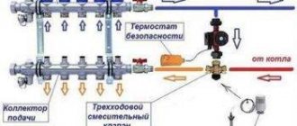
Setting up the VALTEC COMBIMIX pumping and mixing unit
The VALTEC COMBIMIX (VT.COMBI) pump and mixing unit is designed to maintain a given temperature of the coolant in the secondary circuit (due to mixing from the return line). Using this unit, it is also possible to hydraulically link an existing high-temperature heating system and a low-temperature underfloor heating circuit. In addition to the main control elements, the unit also includes the entire necessary set of service elements: an air vent and a drain valve, which simplify the maintenance of the system as a whole. Thermometers make it easy to monitor the operation of the unit without the use of additional devices and tools.
It is permissible to connect an unlimited number of heated floor branches with a total power of no more than 20 kW to the VALTEC COMBIMIX node. When connecting several branches of a heated floor to a node, it is recommended to use VALTEC VTc.594 or VTc.596 collector blocks.
The main adjustment elements of the pumping and mixing unit:
1. Balancing valve of the secondary circuit (position 2 in the diagram).
This valve ensures mixing of the coolant from the return collector of the heated floor with the coolant from the supply pipeline in the proportion necessary to maintain the specified temperature of the coolant at the outlet of the COMBIMIX unit.
The valve setting is changed using a hex wrench; to prevent accidental rotation during operation, the valve is secured with a clamping screw. The valve has a scale with valve throughput values Kvτ from 0 to 5 m3/h.
Note: Although the valve capacity is measured in m3/h, it is not the actual coolant flow rate passing through this valve.
2. Balancing shut-off valve of the primary circuit (pos. 
Using this valve, the required amount of coolant is adjusted that will flow from the primary circuit to the unit (unit balancing). In addition, the valve can be used as a shut-off valve to completely shut off the flow. The valve has an adjusting screw with which you can set the valve capacity. The valve is opened and closed using a hex key. The valve has a protective hex cap.
3. Bypass valve (item 7)
During operation of the heating system, a mode may arise when all control valves of the heated floor are closed. In this case, the pump will operate in a muted system (without coolant flow) and will quickly fail. In order to avoid such modes, there is a bypass valve on the unit, which, when the valves of the underfloor heating system are completely closed, opens an additional bypass and allows the pump to circulate water through a small circuit in idle mode without loss of functionality.
The valve is activated by the pressure difference created by the pump. The pressure difference at which the valve opens is set by turning the regulator. There is a scale on the side of the valve with a range of 0.2–0.6 bar. Pumps recommended for use with COMBIMIX have a maximum pressure of 0.22 to 0.6 bar.
After the heating system is completely assembled, pressure tested and filled with water, it should be adjusted. The adjustment of the control unit is carried out together with the commissioning of the entire heating system. It is best to adjust the unit before starting to balance the system.
Algorithm for setting up the control unit:
1. Remove the thermal head (1) or servo drive.
To ensure that the control valve actuator does not affect the assembly during adjustment, it must be removed.
2. Set the bypass valve to the maximum position (0.6 bar).
If the bypass valve is triggered while the unit is being configured, the setup will be incorrect. Therefore, it should be set to a position in which it will not work.
3. Adjust the position of the secondary circuit balancing valve (item 2 in the diagram).
The required capacity of the balancing valve can be calculated independently using a simple formula:
t1 – coolant temperature on the supply pipeline of the primary circuit;
t11 – temperature of the coolant on the supply pipeline of the secondary circuit;
t12 – coolant temperature in the return pipeline (both circuits are the same);
Kvτ is the control valve capacity coefficient; for COMBIMIX it is assumed to be 0.9.
Calculation example
Initial data: design temperature of the supply coolant – 90 °C; design parameters of the heated floor circuit are 45–35 °C.
The resulting Kv value is set on the valve.
4. Set the pump to the required speed.
To do this, you need to calculate the water flow in the secondary circuit and the pressure loss in the circuits after the unit using the formulas:
G2 = 3600 · Q / s · (t11 – t12), kg/h;
ΔPн= ΔPс + 1, m water. Art.,
where Q is the sum of the thermal power of all loops connected to COMBIMIX; c – heat capacity of the coolant (for water – 4.2 kJ/kg °C; if a different coolant is used, the value should be taken from the data sheet of this liquid); t11, t12 – temperature of the coolant in the supply and return pipelines of the circuit after the COMBIMIX unit. ΔPс – pressure loss in the design circuit of the heated floor (including collectors). This value can be obtained by performing a hydraulic calculation of the heated floor. To do this, you can use the calculation program VALTEC.PRG.
Using the pump nomograms presented below, we determine the pump speed. To determine the pump speed, a point with the corresponding pressure and flow rate is marked on the characteristic. Next, the nearest curve above this point is determined, and it will correspond to the required speed.
Example
Initial conditions: underfloor heating with a total power of 10 kW, pressure loss in the most loaded loop of 15 kPa (1.53 m of water column).
Water flow in the secondary circuit:
G2 = 3600 · Q / s · (t11 – t12) = 3600 · 10 / 4.2 · (45 – 35) = 857 kg/h (0.86 m3/h).
Pressure losses in the circuits after the COMBIMIX unit with a reserve of 1 m of water. Art.:
ΔPн= ΔPс + 1 = 1.53 + 1 = 2.53 m water. Art.
Selected pump speed – MED at point (0.86 m3/h; 4.05 m water column):
If it is not possible to calculate the pump, then you can skip this step and proceed directly to the next one. At the same time, set the pump to the minimum position. If during the balancing process it turns out that there is not enough pump pressure, you need to switch the pump to a higher speed.
5. Balancing the branches of a heated floor.
Close the balancing shut-off valve of the primary circuit. To do this, open the valve cover and use a hex wrench to turn the valve counterclockwise until it stops.
The task of balancing heated floor branches comes down to creating the required coolant flow in each branch and, as a result, uniform heating.
The branches are balanced with each other using balancing valves or flow regulators (not included in the COMBIMIX kit; flow regulators are included in the VTc.596.EMNX manifold block). If there is only one circuit after COMBIMIX, then nothing needs to be linked.
The balancing process is as follows: balancing valves/flow regulators on all branches of the heated floor are opened to the maximum, then a branch is selected in which the deviation of the actual flow from the design one is maximum. The valve on this branch closes to the required flow rate. Thus, it is necessary to adjust all the branches of the heated floor.
When adjusting the VT.FLC15.0.0 flow regulators, you simply need to set the desired flow rate on the scale in l/min by turning the knob. If it is not possible to use a flow indicator, then you can balance the branches approximately by heating the floors or by the temperature of the return coolant.
If during the balancing process it was not possible to obtain the required flow rate through the branches even with the valves open, this means that the hydraulic calculation was performed incorrectly and the pump should be switched to a higher speed.
Setting the primary circuit balancing valve
The balancing valve of the primary circuit is adjusted together with the balancing of the rest of the heating system. The essence of balancing a heating system is to adjust the coolant flow through each heating device, including COMBIMIX, exactly according to the design. If heating systems are not balanced correctly, the system may operate when some of the heating devices are overheated and some are not warmed up enough.
Consider the following diagram of a heating system with a connected COMBIMIX node. This is a two-pipe dead-end heating system with horizontal wiring.
Below the diagram is a piezometric graph. The graph shows the pressure drop in the heating system with green slanted lines. The device located closest to the boiler (or individual heating point) has a greater pressure drop between the forward and return pipelines (vertical lines) than the device located at the end of the system. The orange color on the vertical lines shows the pressure drop across the devices without taking into account the balancing valves, the green color shows the pressure drop that must be created across the valve in order to balance the system. The higher the pressure drop across the device, the greater the flow rate passes through it at the same throughput. In order to equalize the coolant flow in the system, it is necessary to add resistance to devices that are closer to the boiler using balancing valves or control valves. The closer the device is to the boiler, the more resistance must be added using the valve (more valve closing). The graph shows that the valve of the first device is closed so much that its resistance is several times higher than the resistance of the radiator. With the latter device, the valve is practically open and its resistance is low.
Balancing, as a rule, comes down to finding the desired setting of the balancing valves. There are three main ways to perform balancing.
The calculation method consists in the fact that when hydraulically calculating a heating system, a similar piezometric graph is drawn up for the designed heating system. During the hydraulic calculation, the required pressure loss at each balancing valve is determined. Next, the following formula determines the valve capacity:
kv = V /√ΔP, m3/h,
where V is the volumetric flow rate of the coolant, m3/h; ΔP – required pressure loss across the valve, bar.
After calculating the capacity according to the recommendations of the balancing valve manufacturers, the adjuster sets the design capacity value on each valve. Hydraulic calculations must be carried out by a qualified specialist manually or using specialized programs, for example the VALTEC.PRG engineering systems calculation program.
Example
First, let's determine the required coolant flow in the primary circuit. To do this, you can use the following formula:
G2 = 3600 Q /c (t1 – t2),
where Q is the sum of the thermal power of all devices connected after COMBIMIX; c – heat capacity of the coolant (for water – 4.2 kJ/kg °C; if a different coolant is used, the value should be taken from the data sheet of this liquid); t1, t2 – temperature of the coolant in the supply and return pipelines of the primary circuit (the temperatures of the coolant in the return pipeline of the primary and secondary pipelines are the same).
For a heated floor with a total power of 10 kW with a design temperature of the supply coolant of 90 °C, design parameters of the heated floor circuit of 45–35 °C, the coolant flow in the primary circuit will be as follows:
G2 = 3600 · Q /c · (t1 – t2) = 3600 · 10 / 4.2 · (90 – 35) = 155.8 kg/h.
When calculating, the designer determined that the pressure loss on the balancing valve of the unit should be 9 kPa (0.09 bar), in order for the coolant flow in the primary circuit to be 0.159 m3/h, the kv of the valve should be:
kv = 0.159 /√0.09 = 0.53 m3/h.
Next, according to the characteristics of the balancing valve of the primary circuit given below, the number of turns of the adjusting screw is determined.
To determine the number of revolutions, you can not count kv but use the nomogram given below. To do this, plot the required flow through the primary circuit and the required pressure loss across the valve on the graph. The nearest inclined line will correspond to the required setting (number of revolutions). To improve accuracy, you can interpolate the obtained values.
The first line of the table indicates the position, the second line of the table indicates the number of turns of the adjusting screw. (In this example, 2 and ¼.) The third line shows Kv for this setting, as you can see it practically coincides with the calculated one.
Setting the valve speed:
The correct adjustment of the valve should start from the position of the valve being fully closed; using a thin flat-head screwdriver, tighten the adjusting screw until it stops and put a mark on the valve and on the screwdriver.
Using the valve setting table, turn the screw the required number of revolutions. To fix the speed, use the marks on the valve and screwdriver. (following the example, you need to make 2 and ¼ turns).
Using a hex key, open the valve until it stops. The valve will open exactly as much as you turn the screwdriver. After setting the valve, you can open and close it using a hex wrench, while maintaining the capacity setting.
In the same way, all other balancing valves of the heating system are calculated. The number of valve revolutions (or the setting position is determined according to the methods of balancing valve manufacturers).
The second way to balance the system is that the settings of all valves are set “in place”. In this case, the setting values are determined based on the actually measured coolant flow rates for individual branches or systems.
This method is used, as a rule, when setting up large or critical heating systems. During balancing, special devices are used - flow meters, with which you can measure flow in individual directions without opening the pipeline. Balancing valves with fittings and special pressure gauges are also often used to measure the pressure drop, which can also be used to determine the flow rate in individual areas. The disadvantage of this method is that instruments designed to measure flow are too expensive for one-time or infrequent use. For small systems, the cost of the devices may exceed the cost of the heating system itself.
When balancing using this method, COMBIMIX is configured as follows:
Fix the flow meter on the pipeline through which COMBIMIX is connected to the heating system. Calibrate and configure the flow meter according to the instructions for the flow meter.
Then smoothly open the balancing valve using a hex wrench, while recording the change in coolant flow. As soon as the coolant flow corresponds to the design, fix the position of the valve using the adjusting screw.
Example
As for the previous example, the coolant flow rate is first calculated.
For a heated floor with a total power of 10 kW, a design temperature of the supply coolant of 90 °C, and design parameters of the heated floor circuit of 45–35 °C, the coolant flow in the primary circuit will be as follows:
G2 = 3600 · Q /c · (t1 – t2) = 3600 · 10 / 4.2 · (90 – 35) = 155.8 kg/h (0.159 m3/h).
Close the balancing valve completely using the hexagon:
Smoothly open the valve using a hexagon and record the flow rate on the flow meter until the flow rate reaches the design value (in the example, 0.159 m3/h).
After the coolant flow has been established, fix the position of the shut-off valve using the adjusting screw (tighten the adjusting screw clockwise until it stops).
After the adjusting screw is fixed, the valve can be opened and closed using a hexagon, the setting will not be lost.
For small systems in the absence of a design and complex measuring instruments, the following balancing method is acceptable:
In the finished system, turn on the boiler and central pump (or other heat supply source), then close all balancing valves on all heating devices or branches. After this, the heating device that is installed furthest from the boiler (heat supply source) is determined. The balancing valve in this device opens completely; after the device has completely warmed up, it is necessary to measure the temperature difference of the coolant before and after the device. Conventionally, we can assume that the temperature of the coolant is equal to the temperature of the pipeline. Then we move on to the next heating device and smoothly open the balancing valve until the temperature difference between the forward and return pipelines coincides with the first device. Repeat this operation with all heating devices. When the turn comes to the COMBIMIX unit, its adjustment should be carried out as follows: If the coolant temperature in the supply pipeline is equal to the design one, then the balancing valve of the primary circuit should be smoothly opened until the readings on the thermometers of the supply and return pipelines of the secondary circuit are equal to the design ± 5 °C.
If the temperature of the coolant in the supply pipeline during setup of the system differs from the design one, then the following formula can be used for recalculation:
where temperatures with the index “P” are design, and temperatures with the index “N” are adjustment (used for adjustment) values.
Example
Consider the following heating system:
To begin with, all balancing valves are closed.
The heating device that is furthest from the boiler is selected. In this case, it is the rightmost radiator. The radiator balancing valve opens completely. After the radiator has warmed up, the temperature of the forward and return pipelines is recorded.
For example, after opening the valve, the temperature in the supply pipeline was 70 °C, the temperature in the return pipeline was 55 °C.
Then a second device is taken at a distance from the boiler. The balancing valve on this device opens until the temperature in the return pipeline is equal to the temperature of the first ±5 °C.
COMBIMIX setting: design temperature of the supply coolant – 90 °C; design parameters of the heated floor circuit are 45–35 °C. Actual readings taken from thermometers: supply coolant temperature – 70 °C.
Using the formula, we determine the temperature of the coolant in the supply pipeline of the secondary circuit:
We determine the temperature of the coolant in the return pipeline of the secondary circuit:
We open the balancing valve of the secondary circuit until the temperatures on the COMBIMIX thermometers coincide with the calculated ones ± 5 ° C.
Fix the position of the shut-off valve using the adjusting screw (tighten the adjusting screw clockwise until it stops).
After the adjusting screw is fixed, the valve can be opened and closed using a hexagon, the setting will not be lost.
Next, configure all remaining balancing valves in the same way.
Bypass Valve Setting
There are two ways to set the bypass valve:
- If the resistance of the most loaded branch of the heated floor is known, then this value should be set on the bypass valve.
2. If the pressure loss on the most loaded branch is unknown, then the bypass valve setting can be determined from the pump characteristics.
The valve pressure value is set to 5–10% less than the maximum pump pressure at the selected speed. The maximum pump pressure is determined by the pump characteristics.
The bypass valve should open when the pump approaches a critical point, when there is no water flow and the pump works only to build up pressure. The pressure in this mode can be determined from the characteristic.
An example of determining the setting value of a bypass valve.
In this example, it can be seen that the pump, in the absence of water movement at first speed, has a pressure of 3.05 m of water. Art. (0.3 bar), point 1; at average speed - 4.5 m water. Art. (0.44 bar), point 2; and at a maximum of 5.5 m water. Art. (0.54 bar), point 3.
Since the pump is set to medium speed, we select the setting on the bypass valve 0.44 - 5% = 0.42 bar.
6. Final stage
After setting up all the components of the COMBIMIX unit, you should put back the thermal head of the control valve and make sure that the control valve is working. Close the cover of the primary circuit balancing valve. The unit is ready for use.
Setting up heating systems is one of the most difficult engineering tasks. The VALTEC COMBIMIX pump and mixing unit allows you to simplify this task. This unit is a ready-made comprehensive solution for organizing a heated floor circuit in heating systems. A well-thought-out configuration of the unit allows you to eliminate errors when designing a particular system. The flexibility of the unit setup allows you to set up underfloor heating systems without the use of special devices.
*article taken from the website VALTEC.ru
Length of underfloor heating supply line
This is the sum of the pipe lengths from the supply manifold to the beginning of the heated floor circuit and from the end of the circuit to the return manifold.
When placing the underfloor heating collector in the same room as the underfloor heating, the influence of the supply line is negligible. If they are located in different rooms, then the length of the supply line can be large and its hydraulic resistance can be half the resistance of the entire circuit.
Up
Calculator for calculating the length of the water heated floor circuit
Floor heating is one of the most effective and cost-effective ways to heat rooms. Judging from the point of view of operating costs, water “warm floor” looks preferable, especially if the house already has a water heating system. Therefore, despite the rather high complexity of installing and debugging water heating, it is often chosen.
Calculator for calculating the length of the water heated floor circuit
Work on a water-heated floor begins with its design and calculations. And one of the most important parameters will be the length of the pipes in the laid circuit. The point here is not only, and not so much, the cost of material - it is important to ensure that the length of the circuit does not exceed the permissible maximum values, otherwise the operability and efficiency of the system is not guaranteed. The calculator for calculating the length of the water heated floor circuit, located below, can help with the necessary calculations.
Several necessary explanations for working with the calculator are given below.
Calculator for calculating the length of the water heated floor circuit
Go to calculations
Explanations for calculating the length of the contour
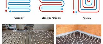
There are many schemes for laying pipes for water-heated floor circuits. One of the fundamental parameters is the laying pitch, that is, the distance between adjacent parallel loops, as shown in the illustration.
Prices for heated floors
warm floor
The illustration clearly shows what a laying step is.
Obviously, the smaller the step, the greater the heat transfer from the laid circuit. But at the same time, the length of the pipe required to implement such a scheme will also increase.
Typically, the pitch is selected from 100 mm (if the “warm floor” becomes the main source of heating of the premises) to 300 mm (if it will only be an “assistant” to the main heating system). It is almost impossible to take a step less than 100 mm for technological reasons (the pipe may break at a small bending radius), and above 300, a “zebra” effect will inevitably appear, that is, alternating warm and cold stripes on the floor surface.
The calculator will help determine the length of the contour at the selected installation step for the specific area of the site where installation will be carried out. In this case, another hidden coefficient is taken into account - for pipe bending.
If the length of a circuit with a pipe with a diameter of 16 mm exceeds 70÷80 mm, and with a diameter of 20 mm – 100÷120 m, you will have to either increase the laying step, or divide the section into two (or more) circuits of approximately the same length. Otherwise, a “closed loop” effect cannot be ruled out, in which the circulation pump simply will not be able to overcome the hydraulic resistance of the pipes, and the movement of coolant through them will stop.
Often, when drawing up installation diagrams, an uneven laying step is used, for example, compacting it against cold walls or thinning it out in areas that do not require strong heating. In this case, you will have to carry out calculations for each section with a certain laying step separately, and then summarize the results.
The final result is given in meters. IMPORTANT : it does not take into account the section of the circuit before connecting to the collector, if the latter is located at some distance from the heated area.
Water heated floor system
The complexity of installation and the high cost of the initial investment should be compensated by the ease of operation and cost-effectiveness of such a system. How to calculate and install a water-heated floor in a special publication on our portal.
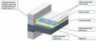
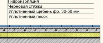
Screed thickness over underfloor heating pipes
The purpose of the screed over the pipes of heated floors is to absorb the load from people and objects in the heated room and evenly distribute the heat from the pipes over the floor surface.
The minimum permissible thickness of the screed above the pipe is 30 mm with reinforcement. With a smaller thickness, the screed will have insufficient strength. Also, the small thickness of the screed does not ensure uniform heating of the floor surface - stripes of hot floor appear above the pipe and cold between the pipes.
It is not worth pouring a screed thicker than 100 mm, because... this increases the inertia of heated floors and eliminates the possibility of quickly adjusting the floor temperature. With a large thickness, a change in the temperature of the floor surface will occur after several hours, or even days.
Based on these conditions, the optimal thickness of the heated floor screed is 60-70 mm above the pipe. Adding fiber and plasticizer to the solution allows you to reduce the thickness to 30-40 mm.
Up
Average floor surface temperature
This parameter is the main criterion for calculating a heated floor in terms of comfort for residents. It represents the average value between the maximum and minimum floor temperature.
According to standards, in rooms with constant presence of people (living rooms, offices, etc.), the average floor temperature should not be higher than 26°C. In rooms with high humidity (bathrooms, swimming pools) or where people are not constantly present, the floor temperature can be up to 31°C.
A floor temperature of 26°C does not provide the expected comfort for the feet. In a private house, where no one has the right to tell the owner what temperature to heat the home at, you can set the average floor temperature to 29°C. At the same time, your feet will feel comfortable warmth. You should not raise the temperature above 31°C - this leads to drying out the air.
Up