Buslaevskaya stove: projects
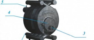
The design has a built-in hood.
The oven is small in size. It is ideal for any private home, as it allows you not only to heat the premises, but also to cook food. Despite its compact size, the stove heats spacious rooms well, which is why there are ready-made designs for houses with a stove. Special schemes for laying brick stoves will help you complete the work without carrying out complex calculations.
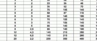
For installation you will need the following materials:
- doors - firebox (0.2x0.25 meters), VK (0.39x0.5 meters), blower (0.14x0.14 meters);
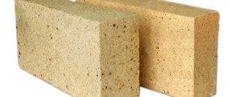
- refractory - 43 pieces;
- solid brick – 382 pieces;
- oven-cabinet 28x33x50 centimeters;
- cast iron stove 0.7x0.4 meters with burners (removable rings of different diameters);
- valves - steam exhaust (12x13 centimeters) and smoke (12x25 centimeters);
- grate - grate 30x20 centimeters;
- corner - three equal-flange blanks 1 meter long and 45x45 millimeters in size;
- steel - piece 0.3x0.28 meters;
- strip - 4 pieces of meter (4 graph paper), 0.25 meters (2 graph paper), 0.35 meters (3 graph paper);
- cast iron plate – 0.4 x 0.25 meters; 40x15 centimeters.
Projects for brick stoves of this type look like this:
- Full row.
- Blower door.
- Window opening for cleaning.
- The bottom of the oven is lined with refractory, three sides are lined with iron.
- Installation of the combustion door, grate, refractory under the firebox, cleaning cover, ash door.
- Installation of DS.
- Laying refractory on the edge around the door.
- Laying according to the scheme.
- The oven is top coated with clay (1 centimeter), the heater is covered, and a stove with burners is attached.
- Installation of smoke circulation with cleaning windows, the stove is not laid. Subsequently, the brick is placed on its edge.
- The cleaning is overlapped, channels are created, and 25-centimeter strips are laid.
- The cleaning is completed and the fastening wire is installed.
- The cap is installed.
- Installation of the VK ceiling, while the hoods remain.
- The stoves are laid out according to the diagram.
- The small stove ends in sheet iron, the masonry is done in the same order as a brick stove.
- The cleaning hole of a large stove is laid out, the edges of the side walls of the channels are cramped.
- Laying protrusions.
- The projections are duplicated and the corner is installed.
- The BP chimney is closed in the same way as row 19.
- A three-row neck is made, the size of the chimney is reduced to a section of 26x13 centimeters for the top valve.
- A chimney is created with grooves on this and subsequent rows.
The dimensions of the structure increase when using clinker facing bricks, so using them instead of solid material is not recommended. When finishing with tiles, durability is ensured (the material lasts for decades), in addition, it can be dismantled for cladding other heating structures.
We are building a furnace with a boiler
When choosing, I tried to find a compact design that could heat a house with an area of more than 100 m², plus I could cook on it.
Tools and materials
| Illustrations | Recommendations |
Tool:
| |
Materials.
| |
| |
| |
| |
| |
Solutions.
| |
|
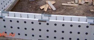
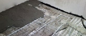
As for the foundation, a separate reinforced concrete foundation must be laid under the brick structure to a depth of about 700 mm, and it should not come into contact with the foundation of the house, the minimum distance is 100 mm.
The monolith is poured 100–150 mm wider than the furnace itself. Before laying the brick, waterproofing is laid (roofing material 2 layers).
The foundation for heavy structures must be exclusively reinforced concrete.
Let's start laying
| Illustrations | Recommendations |
Characteristics.
| |
| Level 1 . It is made continuous and laid on the waterproofing of the foundation. | |
| 2 – 3 levels . At these levels the base for the blower is formed and the blower door is installed. They are laid out the same way. | |
| Level 4 . We begin laying the lining of the combustion chamber. A grate will be installed in this row, so you need to cut grooves in the fireclay bricks for it. The groove is made 5 mm wider than the grille itself. | |
| Boiler installation. The boiler is made in the shape of the letter “P” and covers most of the firebox. I cooked a cauldron from 5 mm thick metal. Basalt cardboard or koalin wool is placed between the boiler and the brickwork, a gap of 5 mm. Boiler dimensions:
| |
The supply pipe is on top, the return pipe is on the bottom.
The window on the rear side of the structure serves to allow flue gases to escape. This boiler model has the highest efficiency; if this is not the main thing for you, then you can install a simple register in the firebox. | |
| Levels 5–6. These levels are almost identical; 2 cleaning hatches are installed in them and a side smoke exhaust channel is formed. In the 5th row, behind the boiler, a half-brick window is left for air intake. | |
| Levels 7–8. Technologically they are the same, only in the 8th row part of the contour is laid out with refractory. At this point, flue gases will exit through a window in the boiler. We place a 50x50 mm corner above the firebox door. | |
| Level 9. We lay the vault above the fire door. Please note that the central brick is cut on both sides at an angle of 45º. We divide the side channel into 2 sectors. | |
| Level 10. Here we do not make a jumper between the firebox sector and the nearest smoke channel. Gases exit the window behind the boiler, go around the boiler from above and are directed into the nearest smoke channel. | |
Level 11.
Both under the hob and under the corner, cutouts are made with a gap of 5 mm. | |
| Level 12 . We close the nearby smoke channel with fireclay bricks. | |
| Level 13 . We continue laying. | |
| Levels 14–15 . In these levels we combine 2 side channels and insert a cleaning door. | |
| Levels 16–17 . After the 16th row, a corner and a 50x6 mm strip are laid above the embrasure of the cooking chamber, and the floor brick is laid on this scaffold. | |
| 18 row . Everything is the same here, only 2 strips of 50x6 mm are placed on top of the cooking chamber. They will become a support for the ceiling. | |
| Row 19 . We close the cooking chamber and install a valve on the side of the steam exhaust duct. | |
| Rows 20–21 . They are placed the same way. Here we insert 4 cleaning hatches and install 2 columns the size of half a brick in the center. | |
| 22 row . Solid bricks are laid on the posts. On the left is T-shaped, on the right is L-shaped. | |
| 23 – 29 rows . These rows are laid in the same way; we drive out the main and auxiliary smoke channels. | |
| Row 30 . In this row, we leave only the main smoke channel intact, all other channels are combined, and the roof of the hood is formed. In the diagram, the passages are shown with arrows. | |
| 31 row . We begin to partially block the channels of the upper cap. | |
| 32 row . We continue to cover the top cap. | |
| 33 row . We completely cover the upper hood, leaving only the chimney channel measuring 260x130 mm. | |
| Rows 34–35. The 34th row is used for dressing the 33rd row. The chimney valve should be installed on top of the 34th row and slightly recessed into the groove cut for it. There is no thirty-fifth row as such; then we remove the chimney. | |
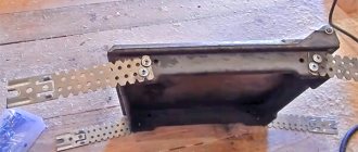
| Metal expansion compensation. A gap must be left between the metal components of the furnace and the brickwork to compensate for the expansion of the metal. To ensure this gap, heat-resistant insulators are used. In the photo, the doors and metal frame are wrapped with asbestos cord. In addition to asbestos cord, you can use asbestos sheet, koalin wool or basalt cardboard with a thickness of 5 mm. | |
| Door fixation. There are fastening holes on the doors and cleaning hatches around the perimeter; previously, annealed steel wire was tied to these holes and embedded in the masonry. Nowadays, mounting tape is used for these purposes. In order for the tape to hold better in the masonry, it is additionally fixed with self-tapping screws, which are driven between the bricks into fresh mortar, as in the photo on the left. | |
| Masonry reinforcement . Brickwork must be reinforced. In our case, it is enough to lay the tape between the rows in problem areas (firebox, doors, hob). |
Scheme for laying a stove for a home
A diagram for laying a stove for a home is the first thing that a person who decides to install heating in his home using a stove will need. In this material we will look at what layout schemes for home brick ovens exist, what are their features and differences.
Laying a stone stove can be done in the following ways:
- 1. undercut;
- 2. with empty seams;
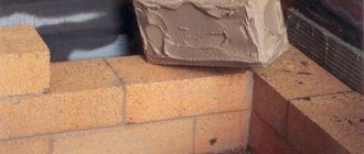
When arranging a stove using the first method, plastering the stove is not required, since all seams are filled with mortar. The thickness of the kiln walls determines the way in which the bricks are laid. The walls are laid out with a thickness of one brick and half a brick. Sometimes you can find a masonry of 3.4 bricks. For work on the installation of a stove, it is imperative to use stove bricks. It is also called “red brick”, solid. Under no circumstances should you use bricks that have been taken from a dismantled building, expanded clay blocks or slotted bricks.
The first row is laid simply with bricks, without using mortar. The brick is leveled, the front wall and the places where all the doors will be located are determined. These operations can be called the last "estimate". When these actions are completed, the bricks are laid with mortar.
After this, they begin to lay the corners. The next stage, according to the advice of experts, is the arrangement of the contour of the entire stove. Using plumb lines, string is stretched from the ceiling to the corners of the stove. With the help of these vertical lines, you can easily navigate while working.
Considering the model of the stove you have chosen, you should determine the areas in which the following will be located: the ash pan, the combustion chamber, and the ash pan. The door under the ash pit is installed when the third row of bricks is laid, and after one row the ash pit is laid out.
After this, the firebox is arranged. Each door is attached with burnt wire. When you get to laying out the vault, you will need to cut the bricks. A calculation will be required to ensure good joining of the bricks with each other. The laying of the vault begins after the second row of bricks is laid after the firebox door.
To line the combustion chamber, special refractory bricks are used. Since facing bricks and masonry bricks have different temperature characteristics, installation of the lining to the furnace itself should not be done rigidly. When installing a chimney pipe, care should be taken to install a special valve, the adjustment of which should be smooth and easy.
Tools for laying a furnace
Regardless of the model chosen, to build a stove with your own hands you will need the following tools:
- trowel or trowel. They are used to apply mortar to bricks, and also use them to clean the masonry from excess mixture protruding between the seams;
- hammer-pick. It is used for trimming and splitting bricks, because in the process of laying bricks it may be necessary to adjust individual elements;
- jointing This tool is used only when the stove will not be decorated with decorative tiles and therefore it must look impeccable;
- building level. Can be used at any stage of construction. It is used to check the evenness of the brick row;
- plumb line Used to measure the verticality of a wall;
- order. An extremely useful device. With its help, the verticality of the masonry is maintained, maintaining an equal thickness of horizontal seams;
- rule. Apply it once to level the surface of the foundation;
- a spatula with which to stir the solution;
- solution container;
- measuring strip for measuring the width of seams.
https://youtube.com/watch?v=a9fxeuKNURg
DIY brick oven
The construction of a brick wood stove requires special knowledge and skills. The difficulty in building such units is that they are heavy. That is why the construction of brick kilns is carried out on a separate foundation. When carrying out brick laying work, it is necessary to strictly observe the rows. Each row has its own unique profile, because the design of the furnace is designed for a special movement of hot gases for more efficient operation. Building brick wood stoves is a real art, which is why, as a rule, only professional stove builders build them.
Where is the best place to install?
The grub can be installed almost anywhere. If your furnace only serves to heat the house, it is better to build it in a utility room to free up space in the main part of the house and prevent smoke from entering the living rooms.
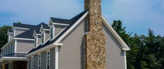
If the user of the stove wants to build a simplified, beautiful fireplace for himself, it is better to install it in a room that is a gathering place for family and guests. Everyone will appreciate an unusual and attractive element of the interior if the stove is built carefully, additionally covering it with a special facing material.
When building a stove with a built-in panel, the best place for installation will be the kitchen. In this case, the grinder functions as a hob; cooking food on it will not only give the food a special taste, but will also significantly save electricity or gas.
It is important that the area where the stove is installed has a sufficiently strong floor. The roof where the chimney passes must not be altered.
How the oven works
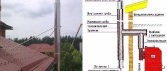
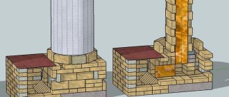
The body of a purely heating stove consists only of a firebox and smoke circuits. Cookers and other types of household stoves may also include stoves, ovens, hot water boxes, etc. The firebox is the main part of the stove. Its design must meet the following requirements: contain the required amount of fuel (at least 75% of the total fuel required for one firebox); ensure sufficient air supply to the burning fuel; maintain high temperature in the combustion zone. The permissible thermal intensity of the firebox volume, equal to 200 - 250 thousand kcal/m³ h, determines its minimum volume. If it is insufficient, the required heat transfer from the furnace will not be ensured. In addition, for ease of laying, the dimensions of the firebox should be a multiple of the dimensions of the brick. The dimensions of the firebox are largely determined by the heat transfer of the stove. Thus, its width for a furnace heat transfer of up to 1000 kcal/h is 120 mm; at 3000 kcal/h – up to 270 mm; with greater heat transfer - up to 500 mm. The length of the firebox is taken to be 260 – 510 mm. For firewood, it is better to have a longer firebox so that the logs can be stacked and burned while lying down. This ensures more complete combustion and therefore greater efficiency. The height of the firebox depends on the type of fuel. When using firewood, it ranges from 420 to 1000 mm, counting from the grate (from 6 to 15 rows of masonry). The grate is usually laid 1 - 2 rows below the level of the fire door so that when it is opened, burning coals do not fall out onto the floor. Sometimes the grate is installed with a slope, in which the rear part is 4–5 cm higher than the front. This rise of the hearth ensures more uniform combustion of the fuel and separation of the flame from the smoke. It is recommended to lay out or line the firebox with refractory or fireclay bricks. The thickness of the walls must be at least ½ brick. If the firebox is covered in the form of a vault, then the radiant energy, reflected from it, will return to the combustion zone, which will improve the combustion process of the fuel. In fireboxes for firewood, both peat with normal humidity (25 - 30%) and coal burn well (the latter burns only on a grate). To burn more moist peat, peat chips and dung, the firebox is made with two grates: horizontal - in the back of the hearth and inclined - in the front. Peat is fired on a horizontal grate. When it flares up, the firebox is loaded with the rest of the fuel, while closing the inclined grate. To prevent small particles of peat and dung from spilling through the grate, the gaps in it should not exceed 8 - 10 mm. In a firebox for burning hard coal and anthracite, it is necessary to provide an enhanced air supply to the combustion zone. This condition is satisfied by installing a grate that is equal in size to the hearth of the firebox. Note that for burning coal, reinforced grates are required (so that they do not burn out quickly) with a plate height of at least 40 mm. Then the air coming from the ash pan to the fuel cools the grate, and it lasts longer. The ash chamber, located under the grate, serves to collect ash and residual unburned fuel particles and mainly to supply air through the ash door and the cracks of the grate to the fuel located in the firebox. The height of the ash chamber is usually three layers of brick. To prevent gases from penetrating into the room when the stove is closed, a through hole with a diameter of at least 10 mm should be provided in the smoke valve or view. To increase the coefficient of performance (efficiency), smoke circulation systems are installed in furnaces. Their purpose is to organize the movement of hot gases coming from the firebox so that, moving through channels and chambers, they give off the optimal amount of heat to the external brickwork. It is very important that the area of the internal heat-receiving surface of the stove chimneys corresponds to the volume of the firebox. So, if the surface area of the chimneys is insufficient, then the heat will go into the chimney unused and this will reduce the efficiency of the stove. If the surface area of the chimneys is excessive, the temperature of the flue gases will be so low that it will cause condensation. For the best absorption of heat, it is necessary that the area of the outer surface of the smoke circulation exceeds the area of the outer heat-releasing surface of the furnace by 30 - 35%. The area of the internal surface of the furnace depends on the cross-section of the smoke circuits, their number and arrangement system. All smoke ducts must have a sufficient cross-section for the free passage of the entire volume of flue gases generated during fuel combustion. As a rule, the dimensions of the channels are a multiple of the size of the brick. The cross-sectional area of the smoke circulation channels must also be consistent with the thermal performance of the furnace. If their cross-section is too large, the oven will not heat up enough, and if it is too small, it will smoke. Experience says that smoke circulation with a furnace heat transfer of up to 3000 kcal/h should have a cross-section of 170 - 250 cm², and with a heat transfer of 3000 - 5000 kcal/h - 250 - 300 cm². In practice, both ductless and ducted chimney systems (smoke circuits) are used, which are divided into single-turn and multi-turn. A single-turn system consists of one lifting channel and one (or several connected in parallel) lowering channels. The advantage of the parallel option is low resistance to the movement of flue gases and more uniform heating of the furnace mass. The disadvantage of a single-turn system is that the upper part of the furnace heats up much more than the lower part. In small stoves this disadvantage is compensated to some extent by fairly strong heating of the walls of the firebox. In large ovens, it is necessary to heat the bottom of the oven, passing the hottest gases through channels located in the lower part of the oven, which ensures the most favorable heating of the room. A multi-turn chimney system includes several successive vertical or horizontal channels. One of the disadvantages of such a system is that moving from the firebox to the chimney, the gases make many turns and therefore experience significant resistance to their movement. Another disadvantage of multi-turn systems is the sharply unequal heating of the furnace in the areas of the first and last channel, and this can lead to cracking of the masonry. Therefore, the use of a multi-turn system is usually not recommended.
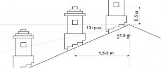
When choosing a channel system, you must also take into account that the vertical smoke circulation system provides greater heat transfer of flue gases, and the horizontal one provides more reliable draft, which is important, say, if the chimney is not high enough. For reasons of fire safety, the upper surface of the stove floor should be located from the ceiling (usually made of combustible materials) at a distance of 35 - 45 cm. The part of the chimney located between the stove body and the groove near the ceiling is called the neck, its minimum height is three rows of flat bricks . Valves or a smoke view are placed in the neck of the furnace, with the help of which the chimneys of the furnace are closed after the end of the fire. Installing these devices below the furnace ceiling level leads to a large loss of heat. The chimney serves to remove flue gases from the furnace and to create draft. If the first of the indicated functions of the pipe does not require explanation, then the draft should be described in more detail. Draft is a vacuum in a section of a channel (in our case, a pipe), under the influence of which a gas flow is created. With natural draft, namely this kind of draft is created in a chimney, the driving force arises due to the difference in the density of gases of different temperatures. Thus, the thrust force mainly depends on the temperature of the exhaust gases and on the height of the pipe. It is not economically profitable to increase the temperature of gases, therefore, in order to improve draft, the height of the pipe should be increased. Experience shows that the distance between the furnace grate and the pipe head must be at least 5–6 m. The furnace draft is also affected by the resistance of the walls of the smoke channel to the movement of gases, which can be reduced by: reducing the number of furnace smoke circulations, increasing the cross-sectional area of the furnace smoke circulations, increasing the area sections of smoke circulation and chimney, creating a smoother surface at the inner walls of smoke circulation and chimney. And finally, the draft decreases sharply if there are even small cracks in the masonry of the stove or chimney (as practice shows, the cause of unsatisfactory draft often lies in defects in the chimney, but not in the firebox). There are three types of chimneys: mounted, resting on the stove mass; indigenous, having a separate foundation; wall, built into the main walls of the house. As a rule, heating and other stoves installed in a rural house are equipped with a mounted pipe, which includes the already mentioned neck, a cut at the ceiling, or fluff, a riser in the attic, a cut at the roof (otter), and a cap. Cutting the pipe serves to protect the wooden structures of the ceiling and roof from fire during the firing of the furnace. It is a thickening of the walls of the chimney where it passes through the ceiling and roof. The thickening is made of brick, reinforced concrete, or a box of sand takes on its role. If it is expected that the kitchen hearth or stove will be heated for more than three hours in a row, then it is necessary to additionally insulate the wooden ceiling structures from the pipe with asbestos or felt impregnated with clay mortar. If felt or asbestos is not at hand, the thickness of the cutting should be increased to 51 cm. The thickness of the walls of the parking lot is at least ½ brick. Between the riser and the head of the pipe, a brick lining is laid - an otter. It prevents rain and snow from entering the attic through the gaps between the pipe and the roof. These gaps are covered with a collar of roofing steel, passing the ends of the sheets under the protruding edges of the otter. When choosing the height of the pipe and its location on the roof, you should follow certain rules to avoid the influence of wind on the draft in the chimney. So, the height of the head depends on the distance of the pipe from the roof ridge. If the pipe is located from it at a distance of up to 1.5 m horizontally, then it should be 0.5 m above the roof ridge. With a distance to the ridge of 1.5 - 3 m, the head should reach the level of the ridge. Another way to combat the effects of wind, which can disrupt draft in chimneys, is to appropriately design the pipe head. For this purpose, the head is either given a special shape, or weather vanes or deflectors are installed on the pipe. Weather vanes that have rotating parts, parts that are out of order. Therefore, it is better to use deflectors as windproof devices, which suck gases from chimneys using wind energy. The most common are injection type deflectors. Connecting two stoves to one chimney is, as a rule, not recommended. If such a need nevertheless arises, then it is necessary that the cross-section of the common channel be no less than 1 x ½ brick, and the distance between both inputs into the chimney along the height of the channel should be at least 0.75 m (between inputs located at the same level , arrange a cut in the form of a vertical wall no less than 0.75 m high, brick thick). The cross-sectional dimensions of the smoke channel depend both on the type of furnace and on its heating capacity. A section of ½ x ½ brick is sufficient for stoves with heat output up to 3000 kcal/h, ½ x ¾ - for stoves with heat output up to 4500 kcal/h. When operating stoves, condensation is often observed on the inner surface of chimneys. Over time, condensation can soak through the masonry, which will require re-lining the damaged sections of the pipe. The formation of condensation depends on many factors, including: the dimensions of the grate, the area of the internal surface of the furnace and the thickness of its walls, the humidity of the fuel used, etc. It should be noted that condensation does not form if the flue gases, when exiting the smoke circuits into the chimney, have a temperature of more than 200 – 250 °C. The easiest way to determine the temperature in the pipe is with the help of a splinter placed during the heating of the furnace for 30 - 40 minutes in one place or another of the pipe. Up to a temperature of 150°C, the color of the wood indicates that the temperature reaches 200°C; brown color corresponds to a temperature of about 250°C. Blackening of wood indicates a temperature of more than 300°C.