For any boiler houses - industrial and domestic, as a rule, one chimney pipe is designed, common to all boilers. In this case, the most important part of the project is the aerodynamic calculation of the chimney.
The material for it can be brick, reinforced concrete, fiberglass. The use of steel analogues with a diameter of more than 1 m is permissible only if there are technical and economic benefits of such a choice.
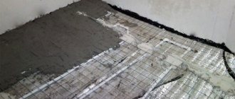
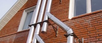
Before installing a chimney, it is necessary to make a number of calculations
Main types of calculations for industrial chimneys
Designing industrial chimneys requires complex, multi-stage calculations
Pipe aerodynamics calculation
Note!
This part of the design is needed to determine the minimum capacity of the structure.
It must be sufficient to ensure trouble-free passage and further removal of fuel combustion products into the atmosphere when the boiler room is operated at maximum load.
It should be noted that incorrectly calculated pipe capacity can cause gas accumulation in the duct or boiler.
A competent aerodynamic calculation makes it possible to objectively evaluate the performance of the blowing and draft systems, as well as the pressure difference in the air and gas paths of the boiler room.
The result of aerodynamic calculations are recommendations from specialists on the height and diameter of the chimney and optimization of sections and elements of the gas-air path.
Determining the height of a structure
The next point of the project is an environmental justification for the size of the pipe, based on calculations of the dispersion of harmful combustion products in the atmosphere.
The height of the chimney is calculated based on the conditions for dispersing the emission of harmful substances.
In this case, all sanitary standards for commercial and factory enterprises must be observed, and the background concentration of these substances must be taken into account.
The last characteristic depends on:
- meteorological regime of the atmosphere in a given area;
- air mass flow speed;
- terrain;
- temperature of exhaust gases and other factors.
During this design stage, the following is determined:
- optimal pipe height;
- the maximum permitted volume of emissions of harmful substances into the atmosphere.
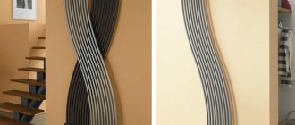
Pipe strength and stability
Calculations are also needed to determine the pipe design
Further, the method for calculating a chimney provides a set of calculations that determine the optimal stability and strength of the structure.
These calculations are made to determine the ability of the selected design to withstand the influence of external factors:
- seismic activity;
- soil behavior;
- wind and snow loads.
Operational factors are also taken into account:
- pipe mass;
- dynamic vibrations of equipment;
- thermal expansion.
Strength calculations make it possible to select not only the design and shape of the structure’s trunk. They also allow you to calculate the foundation for the chimney: determine its design, laying depth, base area, etc.
Thermal calculation
Thermal engineering calculation is required:
- to find the temperature expansion of an industrial chimney material;
- determining the temperature of its outer casing;
- choosing the type and thickness of insulation for pipes.
What is taken into account when determining height?
When designing a chimney, it is important to provide an environmental justification for its dimensions, calculated taking into account the dispersion of emissions of harmful substances into the atmosphere resulting from fuel combustion. The calculation of the height of the boiler room chimney must meet the sanitary standards required for commercial and factory enterprises. In this case, the background concentration of hazardous substances in the atmosphere resulting from the action of other functioning sources of pollution is always taken into account. This value is influenced by the following factors:
- meteorological conditions of the atmosphere at the location of the boiler room;
- speed of air mass flow;
- terrain features;
- temperature of exhaust gases, etc.
Important! Based on the permitted volume of pollutant emissions, the optimal height of the boiler room chimney is calculated. Since the environmental situation in most densely populated areas is unfavorable, the structure in most cases is built above the design indicators corresponding to the minimum possible level. In sparsely populated areas, they are guided by the height of the chimneys of existing boiler houses.
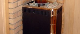
Calculation of chimney parameters in a private house
To determine the parameters of a domestic chimney, complex calculations are not needed
What you need to know when calculating
To determine the parameters of the chimney of a domestic boiler room, there is no need to make serious calculations. It is enough to use a simplified calculation scheme.
Note!
To make such a calculation, you need to know the power (heat output) of the boiler or furnace, in other words: the amount of fuel burned per hour. This figure is easy to find out by looking at the equipment passport.
The remaining parameters for all household structures are approximately the same:
- gas temperature at the pipe inlet – 150/200º;
- their speed in the chimney is not less than 2 m/sec;
- the height of a household chimney, according to SNiP, must be at least 5 m from the grate;
- natural gas pressure per 1 m is not less than 4 Pa (or 0.4 mmH2O)
To find out the value of gravity, it is worth considering what it is: the difference in densities between air and flue gas, multiplied by the height of the structure.
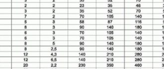
In other words: the calculation of the diameter of the chimney depends on the amount of fuel burned per hour.
Let's assume that you already know the amount of fuel burned, then the volume of gases at the entrance to the pipe, at a certain temperature t, is as follows:
Vg = B∙V∙(1+t/273)/3600, in m³/sec. Knowing the speed at which gases must move in the pipe, you can calculate the area (F) of its cross-section:
F = π∙d²/4, in m²
And, based on the formula for determining the area of a circle, you can calculate the diameter (d) of a round pipe:
dt = √4∙B∙V∙(1+t/273)/π∙ω∙3600, in meters. An example of calculating a pipe, finding the required diameter
Let us give a specific example of how chimneys for domestic use are calculated.
Let it be a metal insulated pipe.
- Let’s assume that 10 kg of wood per hour with a humidity of 25% is burned on the firebox grate.
- Then the volume of gases (V) under normal conditions (taking into account the coefficient of excess air) required for combustion is 10 m³/kg.
- The temperature at the entrance to the pipe is 150º.
- Therefore, Vg = (10∙10∙1.55)/3600. Having made calculations, we obtain a volume of gases of 0.043 m³/sec.
- Taking the gas speed to be 2m/sec, we calculate the diameter of the chimney pipe: d² = (4∙0.043)/3.14∙2, we get the value 0.027.
- We substitute all the numbers into the formula dt = √4∙0.34∙0.043∙(1+150/273)/3.14∙10∙3600. Having made calculations, we obtain the required diameter of 0.165 m.
Definition of gravity
- Let us determine how the gas is cooled per 1 m of the structure. Knowing that 10 kg of wood is burned per hour, we calculate the power: Q = 10∙3300∙1.16, we get the figure 38.28 kW.
- The thermal coefficient for our pipe is 0.34. This means that per meter of its loss will be: 0.34: 0.196 = 1.73º.
- Therefore, at the exit from the 3 meter barrel (from the total 5 m we subtract 2 m of the furnace) the temperature of the gases is: 150-(1.73∙3)=144.8º.
- The value of gravity when determining air density, under normal conditions at 0º = 1.2932, at 144.8º = 0.8452. Let's do the calculations: 3∙(1.2932-0.8452). We obtain a natural gas pressure value of 1.34 mmH2O. This wave is sufficient for normal operation of the pipe.
As you can see, calculating a chimney pipe for domestic use is not as complicated as it might seem.
Did you like the article? Subscribe to our Yandex.Zen channel
Natural and artificial traction.
Artificial draft - occurs as a result of the operation of a fan (equipment with a closed combustion chamber). For example: mounted turbocharged boilers.
Natural draft usually arises due to the difference in the specific gravity of the outside air and flue gases (equipment with an open combustion chamber). For example, floor-standing atmospheric boilers.
In boilers with an open combustion chamber, that is, with natural draft, the combustion air is taken unconditionally from the room in which it is located, and the exhaust gases are discharged into a chimney, which must be provided in the room. When there is no chimney or the boiler will be installed in an apartment, first of all boilers with a closed combustion chamber . In this case, the boiler is equipped with a special smoke removal system.
A furnace (combustion chamber) is a device for burning organic fuel to produce highly heated flue gases.
Increased traction force
Firstly, when the air temperature decreases.
Secondly, when the temperature of the flue gases increases, this is usually achieved by thermal insulation of the entire pipe.
Thirdly, when increasing the height of the chimney.
Fourthly, with a decrease in atmospheric pressure.
Causes of traction disorders.
If traction is disrupted, serious poisoning with carbon monoxide, which is primarily contained in combustion products, is possible. This can lead to serious consequences, including death .
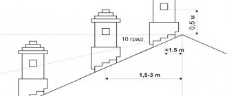
a) Clogging or destruction of chimneys. Placement of heads
b) Leakage of chimneys.
c) Incorrect location of the chimney heads relative to the roof and the wind pressure zone ( backdraft ).
If there is no draft or reverse draft, it is prohibited to use the device
d) Freezing of the chimney tips (if the chimney is poorly insulated).
e) Insufficient air flow into the room.
f) Simultaneous operation of a gas water heater and a mechanical hood above the stove or in the bathroom (reverse draft occurs in the chimney).
Condensation of water vapor.
When the temperature of the flue gases drops below the dew point, the water vapor contained in them condenses.
The dew point temperature when burning natural gas is about 60°C.
Water condensation in the chimney leads to:
Firstly, to reduce cravings.
Secondly, to the destruction of the chimney.
Thirdly, to freezing of the chimney heads in winter.
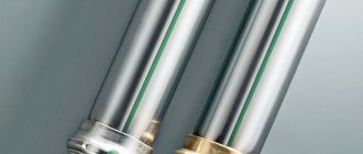
- Violation of thermal insulation
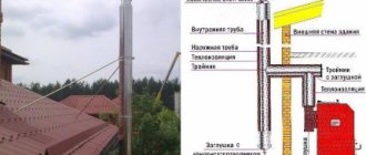
Chimney made from sandwich pipes
Eighteen laws of movement of thermal gases inside a furnace
It is well known that the same phenomenon can be described in different ways. For example: “the wind blew and the tree fell.” This is, so to speak, an emotional description of the event. Another option: “the wind blew at such and such a speed, the tree had such and such a margin of safety (numbers and formulas with evidence that is incomprehensible to a mere mortal), in the end, it still could not stand it and fell.”
For many years I tried to provide a scientific basis for certain laws of the movement of thermal gases inside a furnace, which, in my profession, I had to take into account in one way or another. In the end, I was forced to admit my technical ignorance and incompetence. Alas, I could not formulate anything scientific. But life is life. It was still necessary to formulate what was required for the work. Therefore, let readers with higher education forgive me, but I simply did not find any other way out than to describe the laws of movement of thermal gases inside the furnace according to the principle “the wind blew and the tree fell.” So to speak, only emotions and no formulas, evidence or numbers.
Law 1
The narrower the cross-section of the chimney, the higher the speed of movement of thermal gases through it. And vice versa - the wider the chimney, the lower the speed of gases passing through it.
Law 2
The higher the speed of movement of thermal gases, the more intense the process of heat transfer to the internal walls of the furnace.
Law 3
The farther from the firebox, the colder the gases.
Law 4
To understand the fourth law, you need to combine the first and second ones together. It turns out the following: a wide well will heat up more slowly and longer, and a narrow well will heat up faster and more intensely.
Law 5
In order for the fuel in the stove (the height of the firebox is less than 0.75-1 m) to be able to burn completely, the first one and a half meters of the path of the smoke well must be made with a cross section of at least 25 x 25 cm, or, as stove makers say, two bricks per die ( about 630 cm2). This creates an “afterburning chamber” of combustible gases. This is a very important point, ignoring which leads to the fact that flammable gases simply have nowhere to burn inside the furnace. Over the years, they begin to form a heat-protective film of resinous substances and mossy soot inside the furnace. If the stove has an “afterburning chamber” and excellent draft, then even after 25 years of intensive use there will be absolutely no traces of tar or soot. The bricks will remain clean, as if they were laid in the masonry only yesterday, and not a quarter of a century ago.
Law 6
If the temperature of the gases at the outlet of the pipe is below a certain limit (about 100-150 °C), then the furnace will “cry” (condensation will form). And the householder may cry along with her, because this phenomenon is very unpleasant and not always easily eliminated. So that neither the stove nor the householder “cries,” the shortest overall (double wells are counted as one, see Law 10 of this chapter) length of the chimney path to the exit of the smoke wells from the heated room (ground floor) should not exceed 5-6 m.
Law 7
The seventh law is easier to understand if we carefully consider the fourth. In order for the oven to heat up evenly, you need to make the first well large (and it will not overheat), narrow the second, but so that it is twice as large as the third. The fourth (and also the fifth, if there is one) should be made as narrow as possible (about, but not less than 300 cm2, or one brick per die).
Law 8
If the draft is weak, chimneys will quickly become overgrown with soot and tar. Conversely, with very good draft, they will remain absolutely clean even after 25 years of intensive use of the furnace.
Law 9
If the number of turns of the thermal jet (at an angle of 90°) exceeds 12, nothing will be able to increase the thrust.
Law 10
Twin wells must be counted as one. For example, if we double the first and second wells, then they must already be counted as one. If the jumper between the first and second wells is 40 cm, then only these 40 cm are counted towards the overall shortest path. If the first and second wells have five turns of the thermal jet (at an angle of 90°), and the jumper has only one, then only one turn, etc.
Law 11
Connected heat jets in parallel wells should not be directed towards each other. This will significantly weaken the overall draft of the furnace. The common window in which the connection will take place must also, in its cross section, be the sum of (approximately) the cross sections of the connected wells.
Law 12
Horizontal heat flows must be connected at different horizontal levels (Fig. 28).
| Rice. 28. Flow connection diagram, side section | |
| A. Correct B. Incorrect | |
Law 13
When combining two furnaces into one common pipe, it is advisable to connect them through a distribution box (see paragraph 7 of Chapter 4, Fig. 3).
Law 14
The upper limit of the entrance to the first well should be at least 1-2 cm above the upper limit of the combustion door. Otherwise, the furnace firebox (with the firebox door open) will definitely produce smoke (see paragraph 5 of Chapter 4).
Law 15
Internal section of a horizontal smoke well (side view) Walls of horizontal wells located below 40 cm
from the upper inner surface of the horizontal chimney, are almost not heated by passing hot heat flows. All heat is redistributed over the upper regions of the horizontal chimney, and in the lower layers of the heat flow (below 40 cm) effective heat exchange with the internal walls of the furnace does not occur (Fig. 29).
| Rice. 29. Effectively (a) and ineffectively (b) heated zones of horizontal wells | |
| A. Hot layers of heat flow B. Weakly heated layers C. Internal section of a horizontal smoke well (side view) | |
Law 16
In bell-type furnaces, heat is retained due to the fact that warm air flows, when entering the bell, always try to rise to the top and stay there, and cold air flows choose their paths to move along the lowest zones of the bell (Fig. 30).
| Rice. 30. Movement of heat flows in the bell, side view | |
| a. Hot flows b. Cold streams | |
Law 17
In pipes that are too wide (more than 30 cm in diameter), medium-power household stoves are unable to create active heat flows.
Law 18
An increase in heat flow resistance is facilitated by: a) an increase in the length of the common path of smoke channels (see Law 6); b) change in the direction of heat flows (see law 9); c) areas where thermal channels transform into smaller sections and vice versa.
«previous table of contents next»