Heating devices
These include low-voltage heating electric furnaces (located under radiator casings), electric heaters (located in the ventilation duct), electric boilers, electric stoves (in the boiler room).
All heating devices must be turned on in strict accordance with the operating rules. It is forbidden to hang rags or rags on them for drying. No foreign objects should come into contact with them. When operating heating devices, the conductor is prohibited from leaving the carriage. In addition, they cannot be turned on when the car is powered from the battery, when the generator is faulty, or when power is supplied to an adjacent car.
Operating rules
With the onset of cold weather, the conductors check the serviceability of the combined heating in the car and its preparation for the winter period; the following types of work are carried out:
boiler equipment is checked for malfunctions; attention is paid to the position of taps and valves; the presence of grates and their serviceability are examined in the firebox; the operation of pumps and measuring instruments is corrected; The water in the system is checked. Is there sufficient quantity? The reserve tank is also inspected for the presence of water; pays attention to solid fuel
If there is a shortage, management must be notified; inspection of equipment for working with solid fuels; technical documentation on the rules for using mixed heating of cars is also being put in order.
The lower part of the boiler of a reserved seat carriage
For the normal and uninterrupted functioning of mixed heating, the serviceability of the equipment in each car must be checked, one hundred and ninety-eight heating heads that fit the water-filling pipes.
Before starting up the boiler equipment, it is necessary to check the serviceability of the ventilation system. To do this, you need to look at the position of the valve handle. It is located on the ceiling in the boiler room. When ventilation is running, the position of the handle will be turned to the word “Open”
Another important requirement is to look at the fire damper. By the position of the drive handle you can guess that it is open
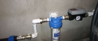
The purpose of the water supply system, its main components
Water supply in passenger cars: diagram for car 61-4179
Sanitary equipment, which is the water supply system for carriages, helps to ensure the necessary conditions of hygiene and nutrition for people during long trips.
Each carriage is equipped with such systems, so passengers are provided with drinking water and water for other household needs. The system is periodically refueled when the train stops.
- Each carriage is equipped with heating and cooling devices. Water is supplied to the toilets, washbasins and dishwashers, which are located in the service area.
- The volume of the entire system in liters is 1200, based on the calculation that no more than 20 liters per day should be consumed per passenger, despite the fact that the system is replenished every 12 hours.
- The plumbing system is gravity-fed, which applies to both hot and cold water.
Passenger reserved seat carriage
Despite the fact that the cars often have different dimensions and structure, the water supply system in them is fundamentally no different.
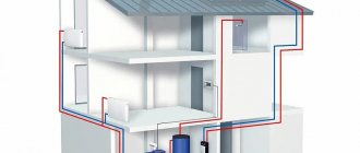
Water supply for TV3 car
We will consider the water supply system for passenger cars using the example of a non-compartment car TV3.
Above is a diagram in which we see:
- Small and large water storage tanks (66 and 86, respectively) - provide the system with cold water. They are spaced on different sides of the car for uniform distribution of liquid. To ensure pressure in the system, the tanks are located under the roof of the car.
- 96 and 99 are filling pipes and filling heads through which containers are filled.
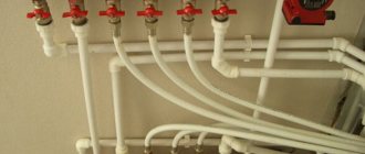
- A network of pipes runs through the entire car , through which cold and hot water circulates.
- The system also contains trays (63, 85, 107) designed to collect condensate and water.
Water supply for passenger cars: boiler for heating water
- Sink (109), boiler (77) and device for cooling cooling water (103);
Car bathroom
- Water disinfectant , a tail pipe, fittings for releasing air from the system and many tap valves.
Now let's talk about all this equipment in more detail.
So:
- A large tank with a capacity of 850 liters is located behind the ceiling of the toilet and corridor at the non-boiler end of the car.
- A small tank with a capacity of 80 liters is above the toilet on the opposite side.
- Two welded pipes approach the body of the large tank, through which the system is filled. These pipes are equipped with shut-off valves to prevent water from splashing while the train is moving.
- There is also a pilot pipe located there, which serves as an overflow when refueling the system, that is, it prevents the tanks from overflowing.
Car water supply diagram: rear view
- The small tank is equipped with a pipe for air outlet, as well as a water meter glass, which allows you to control the level of filling of the tanks.
- Drain valves are installed on the tanks. The drainage occurs into trays through which the liquid goes under the car.
- The large tank is additionally equipped with a tap, which is also located behind the ceiling. It allows you to completely block the highway.
Filling the system
Cold water supply system for passenger cars: water is supplied to the system under a pressure of 10 atmospheres
The tanks are filled with water from the bottom of the car. The supply hoses are connected to the filling heads, which can be seen in the photo above.
Interesting to know! In winter, the heads can freeze, so they are preheated with hot water from the car's heating system.
- Pouring water into a cooled car at an ambient temperature below zero is carried out only after it has been kept in a closed heated room for 24 hours, or after starting the heating system of the car and warming up the air in it to +12 degrees.
- When filling the system, the following taps and valves must be opened: 61,91,69,83 - installed on the water connections to the toilets and washbasins; 68 – valve for air release; 64.65 – taps on water meter glass; 71 – valve for connecting to a hand pump; 78,79 – valves on pipes leading to the boiler; 80 – valve that turns off the main line; 3 – valve for filling the boiler; 140 and 141 valves installed on the filler pipes.
Train at the station
- Even before approaching the station where the system will be refueled, information is taken from the TEM (train electric mechanic) about whether the alarm system that monitors the end of filling is connected.
- If everything is functioning properly, the switch located on the control panel in the service compartment is switched to the “on” position.
- Filling of water will stop when the signal lamp, which is located next to the filling heads, lights up (only on cars equipped with an alarm), or when water appears from the leading pipe and the second filling pipe.
- To prevent water from spilling onto the railway track, a locking device 139 is used. On the side of the filling pipe, the leakage is controlled by filling valves.
Operating trains in winter always presents unforeseen difficulties
In cases of icing of the filling heads or failure of the heater, the system can be filled through a spare filling head (117). It is located in the boiler room near the reserve tank, which means it cannot freeze. With this filling method, an inventory hose is used, which is about 4 meters long.
If such refueling is carried out, the following measures are taken:
- The reserve head valve (70) closes;
- The inventory hose, one side is connected to the reserve head, and the other is led outside through the door and connected to the hose from the water stand located on the tracks.
- Afterwards, it is necessary to open the shut-off valve 70, and the water supply begins, during which you need to ensure that there are no leaks at the junction of the hose with the head.
- As soon as the large tank is completely filled, valve 70 closes, after which the flow of water through the column stops. The hose is disconnected and valve 68 is opened.
The position of the remaining taps and valves is similar to filling through the main filling pipes.
Draining
The cold water supply system of a carriage in a simplified form
To completely drain the water from the system, it is necessary to open all valves and taps. Its instruction manual explains how to drain liquid from a boiler.
- If it is necessary to empty the tanks, hoses are connected to them, which are stretched to the toilets, through which the flush occurs.
- For partial drainage of water, the following are used: mixer (75), toilets (95 and 114), taps (97 and 111).
- If the heating boiler stops operating (at sub-zero temperatures), the water from the water supply system must be drained before draining the water from the heating system.
High-voltage electrical equipment of passenger cars
The high-voltage electrical equipment of passenger cars is powered from the contact wire, through the locomotive pantograph, jumpers (pinches) of the high-voltage main and high-voltage undercar boxes.
If the contact network contains direct current with a voltage of 3000 V, then the boilers are powered directly by it. If the contact network contains alternating current with a voltage of 25,000 V, then a power take-off transformer is installed in the locomotive, which reduces this voltage to 3,000 V, and the boilers are heated by alternating current.
High voltage heating socket
Idle high voltage heating socket
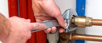
After testing the brakes, the PEM and the driver approach the first car. The PEM connects the car jumper to the locomotive using a special heating key.
To connect the main lines of individual cars to each other into a common main line, it is necessary to sequentially connect all cars to the locomotive. To connect the lines, the pin of one car is inserted into the socket of another car, and the pin of the second car is inserted into the socket of the first car. In this case, two inter-car high-voltage connections are formed between each two cars.
After this, the heating key is handed over to the driver. Further activation of the heating is carried out from the locomotive cabin.
Construction of the boiler and heating element.
The combined heating boiler has the following design. The water jacket of the boiler is made somewhat wide, and 24 | high-voltage heating elements that are mounted on a flange ring. The heating element flange is attached to the ring using two studs with nuts and petal washers. Three insulators are located above the boiler firebox, to which three wires are connected in the pipelines that supply the heating elements.
High-voltage heating elements are covered with a protective casing. A low-voltage interlock in the form of a limit switch is installed on the protective casing, breaking the circuit of the high-voltage contactor coils when the bolts are disconnected and the casing is lifted under high voltage.
When the casing is securely fastened in the lower position, the bolt presses on the limit switch shank, preparing the switching on of the high-voltage contactors. To inspect the elements, the casing is lifted up, having previously unscrewed the bolts, and secured with safety chains.
The high-voltage heating element is made in the form of a steel cylinder. The spiral 12 on a hollow ceramic rod 11 is connected at one end to a bracket 3 mounted on an insulator 2, and at the other end to a return wire 13 passing inside the rod to clamp 1. Insulation of current-carrying parts from the steel body 8 is carried out by a quartz sleeve (glass) 10, an insulator 2 and a ceramic flange 6 with a rubber gasket 7. Flange 6, made together with a ceramic rod 11, is attached to the heater body
bolts 4 with washers 5.
Heat from the coil is transferred to the water through the air surrounding it, the quartz glass, the graphite shell 9, which serves to improve heat transfer, and the heater body. The graphite shell also protects the quartz glass from damage.
that
Each heating element is designed for a voltage of 500 V. In the boiler, the heating elements are assembled sequentially into subgroups of 6 pieces. 2 subgroups are connected into groups in parallel.
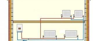
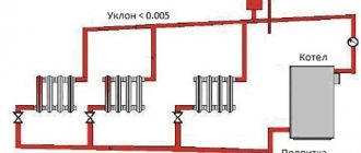
Heating system
Passenger carriages must be equipped with a heating system that ensures the indoor temperature within 20±2 °C. The carriages use two systems:
— water heating from an individual boiler installed in the carriage and running on solid fuel or with combined heating (electricity and solid fuel magma-diesel.ru/);
— centralized electric heating powered from a diesel generator set of a diesel locomotive, a power station car or from the contact network of electrified roads.
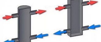
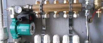
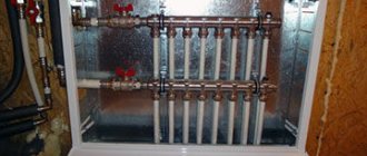
The water heating system from a boiler with combined heating consists of the following components: boiler, plate heater, connecting pipelines, pumps (manual and centrifugal), spare water tank, control devices and control devices.
The connecting pipelines of the heating system are made in the form of straight and curved pipes with welded flanges, branches and other parts. The technology of pipe processing and heating installation involves performing certain operations. Pipe cutting to length is carried out using semi-automatic milling and cutting machines type 8B66 or special pipe cutting machines.
Deburring after cutting is carried out using a device equipped with a grinding wheel or the cutting head of a pipe cutting machine. Pipe bending is carried out in a cold or hot state. Holes in pipes for branches, branch fittings and drain plugs are cut according to markings or overhead templates after bending. Holes with a diameter of up to 40 mm are drilled; holes larger than 40 mm are cut with cutters on vertical drilling machines or cutters. Connecting flanges and various branches are assembled and welded in the jigs, ensuring that the mating working plane of the flange is perpendicular to the pipe axis. The flange plane is pre-processed by cutting a groove for the sealing gasket.
Threading on pipes with coupling connections is carried out on pipe cutting machines. The ends of bent pipes are cut before bending, and during the bending process, safety couplings are screwed onto the threads. Finished heating pipes are tested for strength hydraulically under pressure 50% higher than the working pressure. When testing, a plug is placed on one end of the pipe, and a connecting hose from the pumping unit is attached to the other.
When pressure testing a pipe, its water resistance is checked, especially in welded joints. After testing, the pipes are cleaned, degreased, anti-corrosion coatings are applied to them, dried and completely transferred to the installation position in the car. After installation, a hydraulic test of the entire heating system of the car is carried out, and then the pipes are covered with thermal insulation. Technical felt, foam rubber, etc. are used as heat-insulating materials.