Stage one
This includes an aerodynamic calculation of mechanical air conditioning or ventilation systems, which includes a number of sequential operations. A diagram is drawn up in axonometry, which includes ventilation: both supply and exhaust, and is prepared for calculation.
The dimensions of the cross-sectional area of the air ducts are determined depending on their type: round or rectangular.
Formation of the scheme
The diagram is drawn up in axonometry with a scale of 1:100. It indicates points with located ventilation devices and the consumption of air passing through them.
When building a highway, you should pay attention to what kind of system is being designed: supply or exhaust
Supply
Here the calculation line is lined up from the most distant air distributor with the highest consumption. It passes through supply elements such as air ducts and the ventilation unit right up to the place where the air is taken in. If the system must serve several floors, then the air distributor is located on the last one.
Exhaust
A line is built from the most remote exhaust device, which consumes the maximum air flow, through the main line to the exhaust hood installation and further to the shaft through which the air is exhausted.
If ventilation is planned for several levels and the hood installation is located on the roof or attic, then the calculation line should start from the air distribution device of the lowest floor or basement, which is also part of the system. If the hood installation is located in the basement, then from the air distribution device of the top floor.
The entire calculation line is divided into segments, each of them represents a section of the air duct with the following characteristics:
- air duct of uniform cross-sectional size;
- from one material;
- with constant air consumption.
The next step is to number the segments. It starts with the most distant exhaust device or air distributor, each being assigned a separate number. The main direction - the highway is highlighted with a thick line.
Next, based on the axonometric diagram, its length is determined for each segment, taking into account the scale and air consumption. The latter is the sum of all quantities of consumed air flow flowing through the branches that are adjacent to the main line. The value of the indicator, which is obtained as a result of sequential summation, should gradually increase.
Determination of dimensional values of air duct sections
Produced based on indicators such as:
- air consumption on the segment;
- The standard recommended values for air flow speed are: on highways - 6m/s, in mines where air is taken - 5m/s.
The preliminary dimensional value of the air duct along the segment is calculated and reduced to the nearest standard. If a rectangular duct is selected, then the values are selected based on the dimensions of the sides, the ratio between which is no more than 1 to 3.
How to calculate fan performance
The calculation algorithm is as follows:
- Measure the exact dimensions of the room.
- Multiply the volume by the established air exchange rate.
- The result obtained is the required productivity of the ventilation unit.
Additionally, the cross-section of the air ducts, their geometric configuration, and the resistance of the filter elements are taken into account. The power calculation formula is as follows: L = n*V, where:
- L is the required system productivity;
- n - air exchange standards provided for by SNiP;
- V is the total cubic capacity of the room.
The throughput of the installation is also determined by the diameter of the air channels. Constantly running fans for ventilation must be at least 100 mm.
Calculation of exhaust fan performance in residential premises
Correct calculation of the required performance of the ventilation unit will ensure proper efficiency. To do this, you need to correctly calculate the volume of air, which should be constantly updated. An important requirement for the hood is to ensure a complete exchange of the atmospheric mixture every 15 minutes. According to current regulations, in the kitchen this figure should be at least 9 times per hour.
In the bathroom 5-8 times are enough. To accurately calculate the required productivity of a climate control device, you should know the size of the room being served, which is multiplied by the set air exchange rate. For a kitchen with a volume of 20 m³, the power calculation is carried out as follows: 20x9 = 180 m³/h. This is the minimum acceptable value.
Determining the volume of the room
The cubic capacity of a room is calculated by multiplying the length, width and height. The mathematical formula is as follows: V=a*b*c. The design power of a fan for a bathroom with a volume of 22.5 m³ should be at least 270 m³, which will ensure a complete renewal of the atmospheric mixture every 5 minutes. Additionally, in this room it is necessary to take into account the need to remove water vapor and polluted air. If you perform calculations without taking into account the increased density of the exhaust atmospheric mixture, then the exhaust system may not be able to cope with the load.
For the bathroom and kitchen, it is advisable to choose a fan with a performance reserve to ensure the proper quality of the air mixture in any conditions. The design of the ventilation system also has a significant impact on performance. The corrugated walls of the air duct take approximately 7-9% of the device's power. Losses of filters and noise-absorbing elements are indicated in the accompanying technical documentation. Each right angle of the air duct takes another 2-3% of the power.
Selecting a fan based on the minimum required performance
A certain reserve is included in the design capacity of the ventilation system. In practice, a less productive installation is sufficient. An exhaust fan for a kitchen or bathroom must cope with extreme loads, which include:
- cooking food;
- oven operation;
- taking a shower associated with intense steam formation.
Therefore, the calculation of fan performance is carried out with some margin. Modern models of ventilation systems necessarily have an enhanced operating mode. To ensure the minimum norm under standard conditions, a good air flow and draft in the channel are sufficient.
Intelligent VAV systems can reduce costs and ensure proper sanitation. They have sufficient ventilation and the ability to manually adjust by turning off or limiting air exchange in individual rooms. The required fan performance should not be determined based on a simple formula that does not take into account additional factors. These include:
- The principle of operation of the unit. Modern ventilation systems can operate in standard air exchange or recirculation mode, in which the installation's performance is lower, but it requires more power.
- Placement method. The location of the device in the room also affects the ability to update the atmospheric mixture. The kitchen hood is placed directly above the stove to increase the efficiency of suction of contaminated air.
- Energy consumption. The most economical option is an axial exhaust fan.
In residential premises, a market novelty is often installed - a centrifugal-type device.
Calculation of fan performance for special industrial conditions
When calculating the required performance of a ventilation unit for complex industrial facilities, a technical specification is first drawn up, which includes the expected operating conditions of the climate system. Among them:
- position of the object on the ground;
- the purpose of each room;
- layout and layout of the structure;
- properties of building materials;
- the approximate number of people permanently present inside the building;
- specifics of production and features of technological processes.
Based on this data, calculations of the required power are performed. Additionally, the following are taken into account:
- Air flow speed.
- System noise level.
- Length, geometric configuration and diameter of ventilation ducts.
- Pressure indicators.
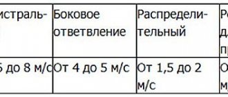
These factors are individual for each industrial facility. The standard air flow speed is 2.5-4 m/s.
Recording the number of people in the room
The performance of the ventilation unit is also affected by the number of people constantly present in the room. There is a special formula that takes this factor into account. It looks like this: L=N*LH.
- L is the minimum required power of the device;
- N is the number of people constantly present at the facility;
- LH is the estimated volume of atmospheric air consumption by 1 person.
The norm of the air mixture in a calm state is 30 m³/h, and during physical activity the body is twice as much. For residential buildings, the value of 60 m³/h is taken as the basis for calculating the required power of the exhaust system. In rest areas, for example, in the bedroom, the standard indicator is 30 m³/h, since during sleep and in the absence of physical activity, the human body’s oxygen consumption is significantly reduced.
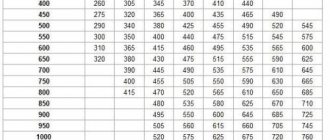
The hood fan used in the kitchen must have some power reserve, since the conditions here are constantly changing. Sometimes higher performance is required, for example when frying food. In a kitchen or bakery with a volume of 30 m³, it is recommended to install a fan with a design power of 400-800 m³/h. Standard air ducts pass no more than 180 m³ within 1 hour.
Therefore, in technical premises, special powerful recirculation systems are used that drive the atmospheric mixture through filter elements. They reduce productivity. Therefore, approximately 40% is added to the design power. Thus, you should choose a recirculation system with a rated productivity in the range of 560-1120 m³/h.
Increased moisture
Equipping rooms with high humidity with an exhaust system has its own peculiarities. To eliminate the possibility of a short circuit in the event of a violation of the integrity of the electrical wiring insulation, special fans with a splash-proof design are used. This model prevents the penetration of droplets and vapors into the air duct.
Regular renewal of air in rooms with poorly established natural ventilation will prevent condensation from settling on tiled and polished surfaces and will reduce the likelihood of mold formation. Modern models of exhaust systems designed for rooms of this type are equipped with a humidity sensor. In a bathroom with an area of more than 5 m², care should be taken to effectively remove the waste air mixture. An exhaust fan with a declared capacity of at least 320 m³/h is recommended.
Initial data for calculations
When the diagram of the ventilation system is known, the dimensions of all air ducts have been selected and additional equipment has been determined, the diagram is depicted in a frontal isometric projection, that is, axonometry. If it is carried out in accordance with current standards, then all the information necessary for the calculation will be visible on the drawings (or sketches).
- Using floor plans, you can determine the lengths of horizontal sections of air ducts. If the heights at which the channels pass are marked on the axonometric diagram, then the length of the horizontal sections will also become known. Otherwise, sections of the building with laid air duct routes will be required. And in extreme cases, when there is not enough information, these lengths will have to be determined using measurements at the installation site.
- The diagram should show, using symbols, all additional equipment installed in the channels. These can be diaphragms, electrically driven dampers, fire dampers, as well as devices for air distribution or exhaust (grills, panels, umbrellas, diffusers). Each piece of this equipment creates resistance to the air flow, which must be taken into account when calculating.
- In accordance with the standards, air flow rates and channel sizes must be indicated on the diagram next to the conventional images of air ducts. These are the defining parameters for the calculations.
- All shaped and branching elements must also be reflected in the diagram.
If such a diagram does not exist on paper or in electronic form, then you will have to draw it, at least in a draft version; you cannot do without it when doing calculations.
Calculation of friction losses
Flow energy losses are calculated proportionally to the so-called “dynamic” pressure, the value pW2/2, where p is the air density at the flow temperature (determined from table (1) and (2)), and W is the speed in a particular section of the air circulation circuit .
The drop in air pressure due to friction is calculated using the Weisbach formula:
=
where l
- length of the circulation circuit section, m,
d eq
- equivalent cross-sectional diameter of the section, m,
d eq
in=
-friction resistance coefficient.
Coefficient
friction resistance is determined by the air flow regime in the considered section of the circulation circuit, or the value of the Reynolds criterion:
Re
=
d eq
where Wi d eq
— speed and equivalent channel diameter and kinematic coefficient of air viscosity (determined from tables /1/ and /2/
,
m/s.
Meaning
Re
values in the range
10 5 -10 8
(developed turbulent value) is determined by the Nikuradze formula:
=3.2 . 10 -3 - 0.231 . Re -0.231
More details optional
can be obtained from /4/ and /5/ In /5/ there is a diagram for finding the value
, facilitating calculations. Calculated values
expressed in pascals (Pa).
Table 3 summarizes the values of the initial data for each channel: speed, length, cross-section, equivalent diameter, Reynolds criterion value, drag coefficient, dynamic pressure and the value of calculated friction losses.
| Table 3 | ||||||||
| Channel number (Fig5) | W, m/s | F, m2 | deq M | l, m |
| Re |
| |
| 1 | 15 | 0.8 | 0,77 | 1,0 | 76,5 | 3,5 . 105 | 0,015 | 1,5 |
| 2 | 25 | 0,87 | 0,88 | 1,75 | 212,5 | 6,7 . 105 | 0,013 | 5,5 |
| 3 | 21,7 | 1,0 | 0,60 | 3,0 | 160,1 | 3,9 . 105 | 0,014 | 11,2 |
| 4 | 28,9 | 0,75 | 0,60 | 1,75 | 283,9 | 5,3 . 105 | 0,0135 | 11,2 |
Calculations of friction resistance in furnace channels
5.3.
“Local” losses - this term refers to energy losses in those places where the air flow suddenly expands or contracts, undergoes turns, etc.
There are quite a lot of such places in the designed furnace - heaters, channel turns, expansion or narrowing of channels, etc. These losses are also calculated as the share of dynamic pressure p = W 2 /2,
multiplying it by the so-called “local resistance coefficient”
:
Sum
29.4Pa
local=
/2
The coefficient of local resistance is determined according to tables /1/ and /5/ depending on the type of local resistance and overall characteristics. For example, in this furnace, local resistance such as a sudden narrowing occurs in channel 1-2 (see Fig. 7). The ratio of sections (narrow to wide). Using Appendix /1 / we find =0,25
=
160Pa,
Other local losses are calculated in exactly the same way. It should be noted that in some cases local losses are caused by the action of two types of resistance at once. For example, if there is a rotation of the channel and at the same time a change in its cross-section (narrowing or expansion), losses should be calculated for both cases and the results added up. The results of local loss calculations are summarized in Table 4
| № | Type of local resistance | W, m/s |
| Note | |
| Sudden contraction | 43,4 | 0,125 | 160 | Nah. according to the table | |
| 1-1 | Rotate 90° | 25 | 1,5 | 318 | ~ |
| 2-3 | Round turn | 25 | ABOUT,1 | 21,3 | ~ |
| 3 | Aperture in flow (heaters) | 35,8 | 3,6 | 601 | ~ |
| 3-4 | Round turn | 21,7 | 0,28 | 44,8 | ~ |
| 4-1 | Rotate 90 with extension | 28,9 | 0,85 | 241 | ~ |
| 4-1 | Sudden contraction | 28,9 | 0,09 | 25,5 | ~ |
Sum
=1411.6 Pa
Total losses:
=30 + 1410 =1440 Pa
We select fans according to centrifugal characteristics
fans, presumably for type VRS No. 10 (working
wheel with a diameter of 1000 mm
).
For a capacity of 21.5 m 3 /s
and the required pressure
H>1440
Pa.. We get: n =550
rpm;
,5; N lips
25 kW.
Fan drive from an asynchronous motor, power 30 kW
AO type at
720 rpm
, through V-belt transmission.
Examples of manual calculations
This is a rather complex task that should be handled by specialists. Often, some companies offer only the arrangement of residential and commercial areas. Basically, this approach is chosen due to the low level of qualifications. They do not have the opportunity to carry out complex operations in which they can take into account the capacity of the workshop equipment, its waste, fumes, the number of people, etc.
Example of calculation in a production workshop
The formula calculates the excess heat transfer Q = Tu + (3.6S - pTu * (Tz - Tp) / p * (T1 - Tp)
Then flammable and simply toxic fumes are calculated using the formula Q = Qu + (X - Qu (Zm - Zp) / (Zu - Zp)
:
- Tu is the volume removed by suction;
- S is the heat generated during operation;
- p—heat capacity;
- Tz - t of the emitted air that is to be removed from the building using a local system;
- T1 - t allocated masses that will be removed using the general exchange network;
- Tp - t incoming flows.
- Zm (mg/m³) - toxins removed by local slopes;
- Zp (mg/m³) - the number of poisons released into the environment;
- Zu (mg/m³) - excreted toxins;
- X (mg/h) - the volume of toxins arising during 1 hour of operation of the workshop.
When calculating air exchange in a workshop, it is also necessary to calculate moisture indicators. This is done using the formula Q = Qu + (V - 1.2 (Pl - Pk) / (P1 - Pk)):
- V (mg/h) – moisture entering the room in 1 hour;
- Pl (g/kg) — removed steam;
- Pk (g/kg)—moisture content in the inflow;
- P1 (g/kg) - the volume of steam output by the central network.
Personnel is also taken into account - Q = C * f
, where C indicates the number of workers, and f the amount of air consumed by one person.
Example of calculation in a store
This uses the above formula to relate the number of people to the resources they consume. However, retail spaces have their own rules. This is where the activity of persons is taken into account. For workers the figure is usually 60 m³/h, and for clients 20 m³/h. Different temperatures are also selected:
- Moves little (cashier) - 22-24 °C at an air supply speed of 0.1 m/s;
- Walks periodically (guard) - 21-24 °C, at speed. 0.1 m/s;
- Moves, carries light objects (merchandiser, spreader) - 19-21 °C at speed. 0.2 m/s;
- Walks a lot, carries objects up to 10 kg (loader in the hall) - 17-21 °C, speed. fans 0.2 m/s;
- Moves a lot and carries heavy things weighing more than 10 kg (loader in a warehouse) - 16-20 °C, speed 0.3 m/s.
Humidity is always set in the range of 40-60%. More in summer, less in winter, because during the cold season the effect of wet clothes in the cold can be created.
Features of calculations in the hot shop and kitchen
This sector has special requirements. Local hoods are actively used here. They must operate at a speed of 0.35 m/s. This means that the feed will be carried out at a similar pace. The amount of air per person should not be lower than 100 m³/h. And temperatures vary from +16 to +27.
Exhaust ventilation is calculated using the formula S=3600*X *B
.
- S (m³/h) – air flow;
- X (m/s)—movement speed;
- B (m²) - section.
At the same time, the indicators of air consumption in the convective flow and the amount of waste removed by the umbrella are calculated.
Features of calculating SW in clean rooms
In medical institutions, requirements for cleanliness and air quality are added. All rooms in the building are divided into 4 categories:
- Very clean - “A”: in maternity wards, burn departments, etc., the number of microorganisms should be no more than 200 CFU/1 m³ before starting, and no higher than 500 during work;
- Ordinary - “B”: in dressing rooms, laboratories, etc. the indicator is lower. It is equal to >500 and >750 CFU/1 m³;
- Conditionally clean - “B”: corridors near operating rooms and maternity rooms. Here >750 and >1000 CFU/1 m³.
There are also dirty blocks - “G”, but there are no special requirements for them.
Stage two
Here the aerodynamic drag values are calculated. After selecting standard sections of air ducts, the value of the air flow speed in the system is specified.
Calculation of pressure loss due to friction
The next step is to determine the specific pressure loss due to friction based on tabular data or nomograms. In some cases, a calculator can be useful for determining indicators based on a formula that allows calculations with an error of 0.5 percent. To calculate the total value of the indicator characterizing the pressure loss over the entire section, you need to multiply its specific indicator by the length. The roughness correction factor should also be taken into account at this stage. It depends on the absolute roughness of a particular duct material, as well as the speed.
Calculation of the dynamic pressure indicator on a segment
Here an indicator characterizing the dynamic pressure in each section is determined based on the values:
- air flow speed in the system;
- air mass density under standard conditions, which is 1.2 kg/m3.
Determination of local resistance values in areas
They can be calculated based on local resistance coefficients. The obtained values are summarized in tabular form, which includes data from all sections, not only straight sections, but also several shaped parts. The name of each element is entered in the table, and the corresponding values and characteristics are indicated there, by which the local resistance coefficient is determined. These indicators can be found in the relevant reference materials on the selection of equipment for ventilation units.
If there are a large number of elements in the system or in the absence of certain coefficient values, a program is used that allows you to quickly carry out cumbersome operations and optimize the calculation as a whole. The total resistance value is determined as the sum of the coefficients of all elements of the segment.
Calculation of pressure losses at local resistances
Having calculated the final total value of the indicator, we move on to calculating pressure losses in the analyzed areas. After calculating all sections of the main line, the resulting numbers are summed up and the total resistance value of the ventilation system is determined.
Calculation of normal air exchange for effective ventilation of an apartment or house
So, during normal ventilation operation, the air in the rooms should constantly change within an hour. The current governing documents (SNiP and SanPiN) establish standards for the flow of fresh air into each of the premises of the residential area of the apartment, as well as the minimum volumes of its exhaust through channels located in the kitchen, in the bathroom, and sometimes in some other special rooms.
These standards, published in several documents, are combined for the convenience of the reader into one table shown below:
| Room type | Minimum air exchange rates (multiplicity per hour or cubic meters per hour) | |
| INFLOW | HOOD | |
| Requirements for the Code of Rules SP 55.13330.2011 to SNiP 31-02-2001 “Single-apartment residential buildings” | ||
| Residential premises with permanent occupancy | At least one volume exchange per hour | — |
| Kitchen | — | 60 m³/hour |
| Bathroom, toilet | — | 25 m³/hour |
| Other premises | At least 0.2 volumes per hour | |
| Requirements for the Code of Rules SP 60.13330.2012 to SNiP 41-01-2003 “Heating, ventilation and air conditioning” | ||
| Minimum outdoor air flow per person: residential premises with constant occupancy, under natural ventilation conditions: | ||
| With a total living area of more than 20 m² per person | 30 m³/hour, but not less than 0.35 of the total air exchange volume of the apartment per hour | |
| With a total living area of less than 20 m² per person | 3 m³/hour for every 1 m² of room area | |
| Requirements for the Code of Rules SP 54.13330.2011 to SNiP 31-01-2003 “Residential multi-apartment buildings” | ||
| Bedroom, children's room, living room | One-time volume exchange per hour | |
| Office, library | 0.5 of volume per hour | |
| Linen room, pantry, dressing room | 0.2 of volume per hour | |
| Home gym, billiard room | 80 m³/hour | |
| Kitchen with electric stove | 60 m³/hour | |
| Premises with gas equipment | One-time exchange + 100 m³/hour for a gas stove | |
| A room with a solid fuel boiler or stove | One-time exchange + 100 m³/hour for a boiler or furnace | |
| Home laundry, dryer, ironing | 90 m³/hour | |
| Shower, bath, toilet or combined bathroom | 25 m³/hour | |
| Home sauna | 10 m³/hour per person | |
An inquisitive reader will probably notice that the standards for different documents are somewhat different. Moreover, in one case the standards are established solely by the size (volume) of the room, and in the other - by the number of people constantly staying in this room. (The concept of permanent stay means staying in the room for 2 hours or more).
Therefore, when carrying out calculations, it is advisable to calculate the minimum volume of air exchange according to all available standards. And then choose the result with the maximum indicator - then there will definitely be no errors.
The first calculator offered will help you quickly and accurately calculate the air flow for all rooms of an apartment or house.
Calculator for calculating the required air flow volumes for normal ventilation
Go to calculations
As you can see, the calculator allows you to calculate both the volume of the premises and the number of people permanently staying in them. Let us repeat, it is advisable to carry out both calculations, and then choose the maximum from the two resulting results, if they differ.
It will be easier to act if you draw up a small table in advance that lists all the rooms of the apartment or house. And then enter into it the obtained values of air flow - for rooms in the living area, and exhaust - for rooms where exhaust ventilation ducts are provided.
For example, it might look like this:
| The room and its area | Inflow rates | Hood standards | ||
| Method 1 – according to the volume of the room | Method 2 – according to the number of people | 1 way | Method 2 | |
| Living room, 18 m² | 50 | 90 | — | — |
| Bedroom, 14 m² | 39 | 60 | — | — |
| Children's room, 15 m² | 42 | 60 | — | — |
| Office, 10 m² | 14 | 30 | — | — |
| Kitchen with gas stove, 9 m² | — | — | 60 | 25 + 100 = 125 |
| Bathroom | — | — | 25 | — |
| Bathroom | — | — | 25 | — |
| Wardrobe-pantry, 4 m² | 2 | — | ||
| Total value | 240 | 177 | ||
| Accepted total air exchange value | 240 |
Then the maximum values are summed up (they are underlined in the table for clarity), separately for air supply and air exhaust. And since when ventilation operates, balance must be maintained, that is, how much air enters the premises per unit time - the same amount must come out, the maximum value from the two total values obtained is also selected as the final value. In the example given, this is 240 m³/hour.
This value should be an indicator of the total ventilation performance in a house or apartment.