The resistance to the passage of air in a ventilation system is mainly determined by the speed of air movement in this system. As speed increases, resistance also increases. This phenomenon is called pressure loss. The static pressure created by the fan causes air movement in the ventilation system, which has a certain resistance. The higher the resistance of such a system, the lower the air flow moved by the fan. Calculation of friction losses for air in air ducts, as well as the resistance of network equipment (filter, silencer, heater, valve, etc.) can be made using the corresponding tables and diagrams indicated in the catalog. The total pressure drop can be calculated by summing the resistance values of all elements of the ventilation system.
Determination of air speed in air ducts:
where L is air flow, m 3 / h; F – channel cross-sectional area, m2.
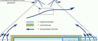
Recommendation 1: Pressure loss in a duct system can be reduced by increasing the cross-section of the ducts to ensure relatively uniform air velocities throughout the system. In the image we see how it is possible to ensure relatively uniform air speeds in a duct network with minimal pressure loss.
Recommendation 2. In systems with long air ducts and a large number of ventilation grilles, it is advisable to place the fan in the middle of the ventilation system. This solution has several advantages. On the one hand, pressure losses are reduced, and on the other hand, air ducts of a smaller cross-section can be used.
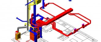
Example of calculation of a ventilation system: The calculation must begin by drawing up a sketch of the system indicating the locations of air ducts, ventilation grilles, fans, as well as the lengths of the air duct sections between the tees, then determine the air flow in each section of the network.
Let's find out the pressure loss for sections 1-6, using the graph of pressure loss in round air ducts, determine the required diameters of the air ducts and the pressure loss in them, provided that it is necessary to ensure the permissible air speed.
Section 1: air flow will be 220 m 3 /h. We assume the diameter of the air duct is 200 mm, the speed is 1.95 m/s, the pressure loss is 0.2 Pa/m x 15 m = 3 Pa (see the diagram for determining pressure loss in air ducts).
Section 2: let’s repeat the same calculations, not forgetting that the air flow through this section will already be 220 + 350 = 570 m 3 / h. We take the diameter of the air duct equal to 250 mm, speed – 3.23 m/s. The pressure loss will be 0.9 Pa/m x 20 m = 18 Pa.
Section 3: air flow through this section will be 1070 m 3 /h. We take the diameter of the air duct equal to 315 mm, the speed is 3.82 m/s. The pressure loss will be 1.1 Pa/m x 20= 22 Pa.
Section 4: air flow through this section will be 1570 m 3 /h. We take the diameter of the air duct equal to 315 mm, speed – 5.6 m/s. The pressure loss will be 2.3 Pa x 20 = 46 Pa.
Section 5: air flow through this section will be 1570 m 3 /h. We take the diameter of the air duct equal to 315 mm, speed 5.6 m/s. The pressure loss will be 2.3 Pa/m x 1= 2.3 Pa.
Section 6: air flow through this section will be 1570 m 3 /h. We take the diameter of the air duct equal to 315 mm, speed 5.6 m/s. The pressure loss will be 2.3 Pa x 10 = 23 Pa. The total pressure loss in the air ducts will be 114.3 Pa.
When the calculation of the last section is completed, it is necessary to determine the pressure loss in the network elements: in the CP 315/900 silencer (16 Pa) and in the KOM 315 check valve (22 Pa). We will also determine the pressure loss in the outlets to the grilles (the resistance of 4 outlets in total will be 8 Pa).
Determination of pressure loss at bends of air ducts
The graph allows you to determine the pressure loss in the outlet based on the bend angle, diameter and air flow.
Example. Let us determine the pressure loss for a 90° outlet with a diameter of 250 mm at an air flow of 500 m 3 /h. To do this, we find the intersection of the vertical line corresponding to our air flow with an inclined line characterizing a diameter of 250 mm, and on the vertical line on the left for a 90° outlet we find the value of pressure loss, which is 2 Pa.
We accept for installation ceiling diffusers of the PF series, the resistance of which, according to the schedule, will be 26 Pa.
Now let’s sum up all the pressure loss values for straight sections of air ducts, network elements, bends and grilles. The desired value is 186.3 Pa.
We calculated the system and determined that we need a fan that removes 1570 m 3 / h of air with a network resistance of 186.3 Pa. Taking into account the characteristics required for the operation of the system, we will be satisfied with the fan; the characteristics required for the operation of the system will suit us with the VENTS VKMS 315 fan.
Determination of pressure loss in air ducts
Determination of pressure loss in a check valve
Selecting the required fan
Determination of pressure loss in silencers
Determination of pressure loss at bends of air ducts
Determination of pressure loss in diffusers
The purpose of the aerodynamic calculation is to determine the cross-sectional dimensions and pressure losses in sections of the system and in the system as a whole. When calculating, the following provisions must be taken into account.
1. On the axonometric diagram of the system, the costs of two sections are indicated.
2. The main direction is selected and the sections are numbered, then the branches are numbered.
3. Based on the permissible speed in sections of the main line, the cross-sectional areas are determined:
The result obtained is rounded to standard values, which are calculated, and the diameter d or dimensions a and b of the channel are found from the standard area.
In the reference literature, before the aerodynamic calculation tables, there is a list of standard sizes of round and rectangular air duct areas.
*Note: small birds that enter the torch zone at a speed of 8 m/s stick to the grate.
4. From the aerodynamic calculation tables for the selected diameter and flow rate in the area, the calculated values of speed υ, specific friction losses R, dynamic pressure R dyn are determined. If necessary, determine the relative roughness coefficient β w.
5. At the site, the types of local resistances, their coefficients ξ and the total value ∑ξ are determined.
6. Find pressure losses in local resistances:
Z = ∑ξ · Р dyn.
7. Determine pressure loss due to friction:
∆Р tr = R l.
8. Calculate the pressure loss in this area using one of the following formulas:
∆Руch = Rl + Z,
∆Руch = Rlβ w + Z.
The calculation is repeated from point 3 to point 8 for all sections of the main line.
9. Determine the pressure loss in equipment located in the main direction ∆Р vol.
10. Calculate the system resistance ∆Р s.
11. For all branches, repeat the calculation from point 3 to point 9, if there is equipment on the branches.
12. The branches are linked to parallel sections of the main line:
. (178)
Lorem ipsum dolor sit amet, consectetur adipiscing elit, sed do eiusmod tempor incididunt ut labore et dolore magna aliqua. Ut enim ad minim veniam, quis nostrud exercitation ullamco laboris nisi ut aliquip ex ea commodo consequat…
The branches should have a resistance slightly greater than or equal to the resistance of the parallel section of the main.
Rectangular ducts have a similar calculation procedure, only in point 4 according to the speed value found from the expression:
,
Lorem ipsum dolor sit amet, consectetur adipiscing elit, sed do eiusmod tempor incididunt ut labore et dolore magna aliqua. Ut enim ad minim veniam, quis nostrud exercitation ullamco laboris nisi ut aliquip ex ea commodo consequat…
and equivalent diameter at speed d υ are found from the tables of aerodynamic calculations in reference literature, specific friction losses R, dynamic pressure P dyn, and L table ≠ L account.
Aerodynamic calculations ensure that condition (178) is met by changing the diameters on the branches or installing throttling devices (throttle valves, dampers).
For some local resistances, the value of ξ is given in the reference literature depending on the speed. If the value of the calculated speed does not coincide with the table one, then ξ is recalculated using the expression:
For unbranched systems or systems of small sizes, the branches are linked not only using throttle valves, but also diaphragms.
For convenience, aerodynamic calculations are performed in tabular form.
Let us consider the procedure for aerodynamic calculation of an exhaust mechanical ventilation system.
| Plot no. | L, m 3 / h | F, m 2 | V, m/s | a×b, mm | D e, mm | β w | R, Pa/m | l, m | Rlβ w, Pa | Type of local resistance | ∑ξ | R d, Pa | Z=∑ξ· R d Pa | ΔР = Rl + Z, Pa |
| Location on | on the magistral | |||||||||||||
| 1-2 | 0,196 | 11,71 | — | 2,56 | 11,93 | 30,5 | 0.42-in. expansion 0.38-confuser 0.21-2branches 0.35-tee | 1,57 | 83,63 | 131,31 | 282,85 | 282,85 | ||
| 2-3 | 0,396 | 11,59 | — | 1,63 | 15,35 | 25,0 | 0.21-3 bend 0.2 tee | 0,83 | 81,95 | 68,02 | 93,04 | 375,89 | ||
| 3-4 | 0,502 | 10,93 | — | 1,25 | 2,76 | 3,5 | 0.21-2 branches 0.1 transition | 0,52 | 72,84 | 37,88 | 41,33 | 417,21 | ||
| 4-5 | 0,632 | 8,68 | 795x795 | 2,085 | 0,82 | 3,50 | 6,0 | 5,98 | 423,20 | |||||
| 2″-2 | 0,196 | 11,71 | — | 2,56 | 6,27 | 16,1 | 0.42-in. expansion 0.38-confuser 0.21-2branches 0.98-tee | 1,99 | 83,63 | 166,43 | 303,48 | |||
| 6-7 | 0,0375 | 5,50 | 250x200 | — | 1.8-mesh | 1,80 | 18,48 | 33,26 | 33,26 | |||||
| 0,078 | 10,58 | — | 3,79 | 5,54 | 21,0 | 1.2-turn 0.17-tee | 1,37 | 68,33 | 93,62 | 114,61 | ||||
| 7-3 | 0,078 | 11,48 | — | 4,42 | 5,41 | 23,9 | 0.17-bend 1.35-tee | 1,52 | 80,41 | 122,23 | 146,14 | |||
| 7″-7 | 0,015 | 4,67 | 200x100 | — | 1.8-mesh | 1,80 | 13,28 | 23,91 | 23,91 | |||||
| 0,0123 | 5,69 | — | 3,80 | 1,23 | 4,7 | 1.2-turn 5.5-tee | 6,70 | 19,76 | 132,37 | 137,04 |
Tees have two resistances - one for passage and one for branch, and they always refer to areas with lower flow rates, i.e. either to the flow section or to the branch. When calculating branches in column 16 (Table p. 88) there is a dash.
To determine the cross-sectional dimensions on any section of the air distribution system, it is necessary to perform an aerodynamic calculation of the air ducts. The indicators obtained from this calculation determine the performance of both the entire designed ventilation system and its individual sections.
To create comfortable conditions in a kitchen, a separate room or a room as a whole, it is necessary to ensure the correct design of the air distribution system, which consists of many parts. An important place among them is occupied by the air duct, the determination of the quadrature of which affects the value of the air flow speed and the noise of the ventilation system as a whole. An aerodynamic calculation of air ducts will allow you to determine these and a number of other indicators.
Stage one
This includes an aerodynamic calculation of mechanical air conditioning or ventilation systems, which includes a number of sequential operations. A diagram is drawn up in axonometry, which includes ventilation: both supply and exhaust, and is prepared for calculation.
The dimensions of the cross-sectional area of the air ducts are determined depending on their type: round or rectangular.
Formation of the scheme
The diagram is drawn up in axonometry with a scale of 1:100. It indicates points with located ventilation devices and the consumption of air passing through them.
Here you need to decide on the main line - the main line from which all operations are carried out. It is a chain of sequentially connected segments with the greatest load and maximum length.
Here you need to decide on the main line - the main line from which all operations are carried out. It is a chain of sequentially connected segments with the greatest load and maximum length.
When building a highway, you should pay attention to what kind of system is being designed: supply or exhaust.
Supply
Here the calculation line is lined up from the most distant air distributor with the highest consumption. It passes through supply elements such as air ducts and the ventilation unit right up to the place where the air is taken in. If the system must serve several floors, then the air distributor is located on the last one.
Exhaust
A line is built from the most remote exhaust device, which consumes the maximum air flow, through the main line to the exhaust hood installation and further to the shaft through which the air is exhausted.
If ventilation is planned for several levels and the hood installation is located on the roof or attic, then the calculation line should start from the air distribution device of the lowest floor or basement, which is also part of the system. If the hood installation is located in the basement, then from the air distribution device of the top floor.
The entire calculation line is divided into segments, each of them represents a section of the air duct with the following characteristics:
- air duct of uniform cross-sectional size;
- from one material;
- with constant air consumption.
The next step is to number the segments. It starts with the most distant exhaust device or air distributor, each being assigned a separate number. The main direction - the highway is highlighted with a thick line.
Next, based on the axonometric diagram, its length is determined for each segment, taking into account the scale and air consumption. The latter is the sum of all quantities of consumed air flow flowing through the branches that are adjacent to the main line. The value of the indicator, which is obtained as a result of sequential summation, should gradually increase.
Determination of dimensional values of air duct sections
Produced based on indicators such as:
- air consumption on the segment;
- The standard recommended values for air flow speed are: on highways - 6m/s, in mines where air is taken - 5m/s.
The preliminary dimensional value of the air duct along the segment is calculated and reduced to the nearest standard. If a rectangular duct is selected, then the values are selected based on the dimensions of the sides, the ratio between which is no more than 1 to 3.
Calculation of exhaust ventilation
The calculation of exhaust ventilation is carried out after calculating the supply ventilation and is based on ensuring the balance of supply and exhaust air at the facility. When calculating exhaust ventilation, rooms are identified that require separate exhaust systems. In particular, a separate hood is provided for bathrooms and showers. In this case, an exhaust amount of 50 m3/h is provided for each occupant, 25 m3/h for each urinal and 75 m3/h for each shower room. A separate hood is also provided for kitchens and food preparation areas. The exhaust from kitchens depends on the type of stove and is usually 90 m3/h. If we are talking about the kitchen premises of cafes and restaurants, then local suction should be provided from special kitchen equipment in accordance with the design assignment. The calculation of exhaust ventilation for office premises is based on ensuring a positive 20% imbalance. So, if the influx into an office space for 10 workplaces and 5 visitors is 700 m3/h, then the exhaust air flow rate should be 560 m3/h. A separate task is to reduce the costs of supply and exhaust ventilation systems and ensure their equality for the facility as a whole. To calculate and design ventilation for specific objects, please contact IS “Ecolife”. Our engineers will help you make the right ventilation for any type of facility.
To contents
Stage two
Here the aerodynamic drag values are calculated. After selecting standard sections of air ducts, the value of the air flow speed in the system is specified.
Calculation of pressure loss due to friction
The next step is to determine the specific pressure loss due to friction based on tabular data or nomograms. In some cases, a calculator can be useful for determining indicators based on a formula that allows calculations with an error of 0.5 percent. To calculate the total value of the indicator characterizing the pressure loss over the entire section, you need to multiply its specific indicator by the length. The roughness correction factor should also be taken into account at this stage. It depends on the absolute roughness of a particular duct material, as well as the speed.
Calculation of the dynamic pressure indicator on a segment
Here an indicator characterizing the dynamic pressure in each section is determined based on the values:
- air flow speed in the system;
- air mass density under standard conditions, which is 1.2 kg/m3.
Determination of local resistance values in areas
They can be calculated based on local resistance coefficients. The obtained values are summarized in tabular form, which includes data from all sections, not only straight sections, but also several shaped parts. The name of each element is entered in the table, and the corresponding values and characteristics are indicated there, by which the local resistance coefficient is determined. These indicators can be found in the relevant reference materials on the selection of equipment for ventilation units.
If there are a large number of elements in the system or in the absence of certain coefficient values, a program is used that allows you to quickly carry out cumbersome operations and optimize the calculation as a whole. The total resistance value is determined as the sum of the coefficients of all elements of the segment.
Calculation of pressure losses at local resistances
Having calculated the final total value of the indicator, we move on to calculating pressure losses in the analyzed areas. After calculating all sections of the main line, the resulting numbers are summed up and the total resistance value of the ventilation system is determined.
Basic formulas for aerodynamic calculations
The first step is to make an aerodynamic calculation of the highway. Let us remind you that the main air duct is considered to be the longest and most loaded section of the system. The fan is selected based on the results of these calculations.
When calculating the main branch, it is desirable that the speed in the air duct increases as it approaches the fan!
Just don’t forget about linking the remaining branches of the system. It is important! If it is not possible to make connections on the branches of the air ducts within 10%, you need to use diaphragms. The diaphragm resistance coefficient is calculated using the formula:
If the discrepancy is more than 10%, when a horizontal air duct enters a vertical brick duct, rectangular diaphragms must be placed at the junction.
The main task of the calculation consists of finding the pressure loss. At the same time, I select the optimal size of the air ducts and control the air speed. The total pressure loss is the sum of two components - pressure loss along the length of the air ducts (due to friction) and losses in local resistance. They are calculated using the formulas
These formulas are correct for steel air ducts; for all others, an correction factor is introduced. It is taken from the table depending on the speed and roughness of the air ducts.
For rectangular air ducts, the calculated value is the equivalent diameter.
Let's consider the sequence of aerodynamic calculation of air ducts using the example of offices given in the previous article, using formulas. And then we’ll show you what it looks like in Excel.
Calculation example
According to calculations, the air exchange in the office is 800 m3/hour. The task was to design air ducts in offices no more than 200 mm high. The dimensions of the room are given by the customer. Air is supplied at a temperature of 20°C, air density 1.2 kg/m3.
It will be easier if the results are entered into a table of this type
First we will do an aerodynamic calculation of the main line of the system. Now everything is in order:
- We divide the main line into sections along the supply grilles. We have eight grates in the room, each with a capacity of 100 m3/hour. There were 11 sections. We enter the air flow at each section into the table.
- We record the length of each section.
- The recommended maximum speed inside the duct for office premises is up to 5 m/s. Therefore, we select the size of the air duct so that the speed increases as it approaches the ventilation equipment and does not exceed the maximum. This is done to avoid noise in ventilation. Let’s take an air duct of 150x150 for the first section, and 800x250 for the last section.
V1=L/3600F =100/(3600*0.023)=1.23 m/s.
V11= 3400/3600*0.2= 4.72 m/s
We are satisfied with the result. We determine the dimensions of the air ducts and the speed using this formula in each section and enter them into the table.
Stage three: linking branches
When all the necessary calculations have been carried out, it is necessary to link several branches. If the system serves one level, then branches not included in the main line are linked. The calculation is carried out in the same order as for the main line. The results are entered into the table. In multi-storey buildings, floor branches at intermediate levels are used for linking.
Linking criteria
Here the values of the sum of losses are compared: pressure along the linked sections with a parallel connected main line. It is necessary that the deviation is no more than 10 percent. If it is determined that the discrepancy is greater, then the linkage can be carried out:
- by selecting the appropriate cross-sectional dimensions of the air ducts;
- by installing diaphragms or throttle valves on the branches.
Sometimes all you need to make such calculations is a calculator and a couple of reference books. If you need to carry out an aerodynamic calculation of the ventilation of large buildings or industrial premises, then you will need an appropriate program. It will allow you to quickly determine the dimensions of sections and pressure losses both in individual sections and in the entire system as a whole.
Design of ventilation systems.
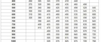
The main requirement for all types of ventilation systems is to ensure optimal air exchange rates in rooms or specific work areas. Taking this parameter into account, the internal diameter of the air duct is designed and the fan power is selected. In order to guarantee the required efficiency of the ventilation system, the pressure loss in the air ducts is calculated; these data are taken into account when determining the technical characteristics of the fans. Recommended air flow rates are shown in Table No. 1.
Algorithm for calculating air pressure losses
The calculation must begin with drawing up a diagram of the ventilation system with the obligatory indication of the spatial location of the air ducts, the length of each section, ventilation grilles, additional equipment for air purification, technical fittings and fans. Losses are determined first for each individual line and then summed up. For a separate technological section, losses are determined using the formula P = L×R+Z, where P is the loss of air pressure in the design section, R is the loss per linear meter of the section, L is the total length of the air ducts in the section, Z is the loss in the additional fittings of the system ventilation.
To calculate pressure loss in a round duct, the formula Ptr is used. = (L/d×X) × (Y×V)/2g. X is the tabulated coefficient of air friction, depends on the material of the air duct, L is the length of the design section, d is the diameter of the air duct, V is the required air flow speed, Y is the air density taking into account temperature, g is the acceleration of fall (free). If the ventilation system has square air ducts, then table No. 2 should be used to convert round values to square ones.
Table No. 2. Equivalent diameters of round air ducts for square ones
The horizontal axis indicates the height of the square duct, and the vertical axis indicates the width. The equivalent value of the circular section is found at the intersection of the lines.
The horizontal axis indicates the height of the square duct, and the vertical axis indicates the width. The equivalent value of the circular section is found at the intersection of the lines.
Air pressure losses in bends are taken from table No. 3.
Calculation of natural ventilation
Natural ventilation is calculated based on the pressure difference at different atmospheric altitudes. In fact, a vertical section of the air duct connects points with different atmospheric pressure, due to which draft is naturally formed. Moving air pressure is determined by the formula: Р=(Рвн–Рн)·h·g, where Рвн – density of internal air (kg/m3), Рн – density of external air (kg/m3), h – height of natural exhaust (m) , g is the acceleration of gravity, equal to 9.81 m/s2. In fact, this pressure is equal to the aerodynamic resistance of the vertical section of the duct under consideration. Next, based on the obtained aerodynamic resistance for a given air duct, the corresponding air flow rate is determined.
To contents