Warm floors are truly a blessing to civilization. It is especially relevant if it is installed on the first floors of residential buildings or in apartments located above the basement. Warm floors can make your home feel cozy. Unfortunately, like any other electrical system, such floors can also fail, at one point ceasing to heat the room. Of course, the system needs careful testing and troubleshooting. And immediately after installation, even before pouring the screed and laying the finishing touches, it is important to find out its performance. How to check a heated floor?
How to check a heated floor
Types of electric heated floors
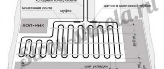
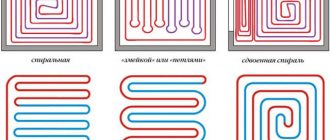
Cable designs and placement
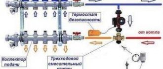
A floor heating system, created from an electric cable or infrared film, in any case has certain elements. This is the heating cable itself, which is the source of heat, a temperature sensor that takes readings of the heating temperature of the wire, as well as a thermostat, which is responsible for connecting all the floor elements into a single whole and regulates the processes of turning it on/off depending on the heating level of the cable.
Cable heated floor
Cable for heated floor
A thermostat or thermostat looks like a small switch; it regulates the amount of voltage that is supplied to the wires. It is connected to a regular electrical network using two wires - phase and neutral. The device regulates the voltage automatically; it is supplied to the heating cable as soon as the floors in the room cool down. The heating of the floors is monitored by a temperature sensor, which is installed in close proximity to the cable and filled with screed.
Connection diagram for electric heated floor
On a note! The temperature at which it is necessary to turn on the heated floor system is set by the residents themselves. Therefore, you can easily choose a comfortable heating level.
The cable used during the installation of heated floors can be divided into two types - resistive and self-regulating. The latter itself reacts to temperature changes and changes the resistance level. But a resistive cable does not have this ability.
Cable for underfloor heating - resistive and self-regulating
Attention! When calculating the performance of a heated floor system and its installation, it is important to remember that the length of some types of cable must be certain. If you shorten it, you can change the heating level and current characteristics (indicators), which is why the wires will not work correctly and the insulation on them will be destroyed.
To create a warm floor, you can use a single two-core cable or two single-core cables arranged in parallel. The first is a grid consisting of wires with a plug on one side. Such a cable cannot be cut and it cannot be laid in a screed where large-sized furniture or equipment will be located.
The structure of a two-core heating cable for heated floors
But as for single-core cables, you can cut them any way you like - no harm will happen to the insulation. Yes, and infrared floors can be cut to the size of the area in need of heating, but only along strictly designated lines.
Connecting a heated floor to a thermostat
Prices for heated floors Caleo
warm floor caleo
Checking the heated floor upon purchase and after installation
The heated floor is checked upon purchase, before pouring, or if the cable breaks for repair.
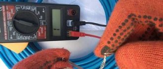
The first check of the heated floor with a multimeter is carried out at the time of purchase. The seller is obliged to demonstrate all the functionality of the product at the request of the client. The product must be accompanied by documentation with the specified technical characteristics, insulation resistance values and mats. This data must be checked against the actual readings of a tester or multimeter.
After laying the heating elements, but before installing the floor covering or pouring the screed, it is necessary to check the operation of the heated floor a second time. To do this, you first need to make sure that the heating cable is intact. Then the system is connected to the mains and the operation of different modes is observed for some time. At this stage, it is important to ensure that the temperature sensor and thermostat are functioning correctly. Correct operation requires uniform heating of all sections of the cable. The heating temperature of the elements must change in accordance with the specified parameters of the thermostat.
If a malfunction is discovered during the installation process, it is best not to look for the problem or try to solve it, because This is most likely a warranty issue. You should contact the store where you purchased the product and replace it with a working version.
Malfunctions of heated floors
And now, it would seem, the system is installed, everything is connected, but for some reason the floor does not want to become warm. If heating does not occur, it means that somewhere during installation an error was made or faulty equipment is used in the system.
Table. The main causes of floor heating malfunctions.
| Floor element | Malfunction |
| Thermostat | A capacitor or relay inside the thermostat may fail. Repairing this device will be expensive, and the easiest way is to replace it with a new one. The main thing is to see what brand the previously installed device was from. The fact is that the temperature sensor and thermostat must be produced by the same manufacturer. |
| Thermal sensor | This is, one might say, a consumable item. It is quite easy to replace if necessary. Depending on the quality, it can work for a long time or for a very short time. But the length of its service life also largely depends on how correctly it is installed. It must be inside the corrugated tube and located relative to the heating cable at a certain angle and in a certain place. |
| Heating cable | As a rule, the cable can only deteriorate if it is installed incorrectly. The rules for connecting the system to the electrical network or its installation may be violated. The most vulnerable part of the wire is the coupling. |
Electronic thermostat for heated floors
Advice! To avoid having to frequently repair the underfloor heating system in your apartment, it is recommended to purchase reliable equipment from trusted manufacturers.
What does high power consumption mean?
If a comparison of values shows a high power consumption, this indicates that there are short circuits resulting from a violation of the integrity of the wire insulation. In this case, part of the floor will heat up very much, while the other will not work. In this mode, the entire system will not work for a long time, and a lot of electricity will be consumed, which, of course, is uneconomical.
Power of electric mats
This problem can only be solved if it is possible to remove the topcoat. If the cable was laid under a screed, this will not be possible.
What does low power consumption indicate?
If the amount of power consumed is much less than that indicated in the product data sheet, then this indicates an open circuit. In this case, the resistance will be very high, which may lead to cable burnout. You can determine the location of the break if it is possible to remove the entire finishing coating or dismantle a section of it.
Measuring the insulation resistance of a heated floor with a megohmmeter
Action plan:
- you need to disconnect the heated floor from the thermostat and the electrical network;
- The break point is searched using a high-voltage generator and an audio detector. The operating principle of such a device is similar to a metal detector. It passes along the surface of the floor and signals a loss of current - this is the break point;
Diagram of the underfloor heating thermostat in the electrical network - Having identified a break, the coating is dismantled in this place;
- damaged wires are stripped, connected with sleeves and compressed with press pliers;
- the heat-shrinkable sleeve is heated with a hair dryer, and when it cools, it shrinks and becomes a sealant for the restored wire;
- Next, the floor covering is installed.
Methods for checking the serviceability of a heated floor
There are only two ways to check the functionality of the underfloor heating system. One of them is a visual inspection of the cable and components for damage . But it will allow you to identify only those defects that can be seen - burnt (blackened) equipment, a broken cable, lack of electricity in the house, etc. The method is the simplest and does not require the use of any devices, but it is not very informative and will not always be able to help in identifying the reason for the lack of floor heating.
Inadmissible rotation of the heating mat after the factory coupling. During cable operation, constant deformation of the outer sheath occurs
The second method is to determine the basic parameters of the system power supply using a multimeter . It will help you find out more precisely what is the reason for the lack of performance of the floor. Using the device, you can measure the network voltage - just remove the thermostat from the wall and, using special probes on the terminals, measure the network voltage. It should be 220 V. If the indicator is normal, it means that the culprit is definitely one of the elements of the entire floor heating system.
The first step is always a visual inspection. It is important to make sure that the reason for the lack of heat is not a lack of electricity throughout the house. Next, you can look for the presence of melted or burnt parts of the system. If nothing suspicious is found, then it’s time to pick up a multimeter.
Multimeter
A multimeter is also used to diagnose the underfloor heating system. The cable resistance is measured and divided by the value of 220 V (this is an indicator of the voltage in the electrical network). The resulting figure shows the master the amount of current flowing through the floor system. Next, this indicator is multiplied by the voltage - this is how the power consumption indicator is determined. It is this that must correspond to the power of the system, which is usually indicated in the passport. If the power value is greater than needed, then there are short circuits in the system - the cable insulation is damaged somewhere.
Attention! This type of malfunction can also be noticed due to excessively heated areas of the floor in some places.
Infrared heated floor - electricity consumption
If the power value is less than indicated in the cable passport, it means that there is a wire break somewhere. Because of this, the system is unstable.
Advice! If all documentation regarding floor heating equipment is irretrievably lost, then the power according to the passport is assumed to be conditionally equal to 150 W/m2.
Let's look further: if the resistance reading on the multimeter is 0, then, most likely, it was disabled by a short circuit that occurred somewhere. Repairing the equipment will be extremely difficult and expensive. And it will be difficult to find the damaged area if we are talking about a cable field. If infrared flooring is used for heating, then it is enough to lift the finish, find the damaged area and change it.
Laying infrared heated floors
Checking when a fault occurs
During the installation or further operation of a heated floor, as with any other devices, malfunctions may occur. The user can call a technician to fix the problem or do the repairs themselves. In general, no special difficulties should arise. However, diagnostic methods and causes of malfunctions may differ for different types of systems.
Diagnosis of water heated floor malfunctions
First of all, check the pressure in the underfloor heating circuit.
When a water heated floor is installed in the house, which is connected to central or autonomous heating, there may be several reasons for the lack of heating. Diagnostics of the system is performed when it is fully turned on.
If there is no heating throughout the house, the hydraulic pump is faulty or the filter is clogged. There may not be enough water in the distribution tank or the water heating boiler is not working. The first step is to check the liquid level in the expansion tank, because in 20% of cases this is the cause of the malfunction.
If some part of the heated floor does not heat up, for example, one room, the coil is most likely faulty or the filter is clogged.
When there is enough water, the filters are cleared of contaminants, but the heating problem persists, you should check for an air lock. For this purpose pumping is carried out. The air valve opens, water gradually squeezes air out of the expansion tank. Once the air is completely released, liquid will begin to drip from the air valve. Next, the valve closes tightly and the system is refilled with water.
Due to a breakdown of the circulation pump, liquid will not flow into the circuit
The cause may also be incorrect operation of the circulation pump. It should work smoothly, without extraneous noise or vibration. If this is not the case, the pump should be replaced.
It would be a good idea to check the pressure in the system. To do this, a pressure gauge is installed after the pump. In normal condition it should show 0.5 bar. The cause of low pressure is a leak in the pipe. In this case, it is necessary to determine the location and open the problem area to repair it.
Another reason for the lack of heating of the water floor may be clogging of pipes with silt deposits. They are formed due to poorly filtered water. Only specialists can remove the blockage using special reagents.
Diagnosis of electric floor heating faults
If the cable is disconnected at the panel, this indicates a short circuit.
First, you should make sure that there is electricity in the house and that it is supplied to the thermostat. Check the glow of the light bulb or display panel on the device. Next you need to check the temperature settings. If everything is normal here, check further.
- There is no heating over the entire area. When the heated floor is connected to the network, the circuit breaker in the panel is switched off by the protection, this indicates a short circuit in the cable. To determine the location of the damage, the voltage is turned off and the supply wires are disconnected from the thermostat. You need to ring the section between the shield and the regulator. The multimeter shows zero resistance - the wiring in this place is damaged. Otherwise, the search continues. The heating cable is disconnected from the thermostat; you need to measure the resistance at its input. If a short is detected here, the damage is inside the regulator and it must be replaced. If there is no short circuit, only the heating cable itself remains. The resistance between its wires is measured. If the readings on the device screen tend to infinity, this indicates a cable break.
- Temperature is not regulated. If the underfloor heating elements warm up over the entire area, but do not respond to changes in the values on the thermostat, it means the regulator is not functioning correctly or the temperature sensor is faulty. In the first case, the thermostat must be replaced. In the second, the temperature sensor wires are disconnected from the regulator and the resistance between them is measured. The value must match the data from the manufacturer's documentation. If the values do not match, the floor covering is removed and the sensor is replaced with a new one.
- Certain areas do not heat up. The heating uniformity is checked using a thermal imager. If heating is uneven, you need to check the amount of power consumed. If it is less than that declared by the manufacturer, the heating cable has broken and some of the elements remain de-energized. The system consumes increased power - a short circuit has occurred between individual cable elements. With this option, some of the heaters do not function, and the other part consumes an excessive amount of electricity.
Checking cable or infrared film heated floors for faults using a multimeter must be done at all stages of working with heating elements. This will help you purchase and install proper equipment. If a problem arises during operation, a multimeter will help you correctly identify and independently cope with the breakdown, make repairs or replace failed parts of the system.
How to check the temperature sensor
If the floor itself is working, but the system still does not work, then the reason lies elsewhere. You can try to check the serviceability of the sensor. It is a resistor that has its own resistance, and this can also be measured using a multimeter. But the performance of the latter varies greatly depending on what the floor temperature is at the moment. For example, with a temperature reading of 5 degrees, the multimeter will show a value of 22 kOhm, and with a temperature reading of 40 degrees – only 6 kOhm. In general, the indicator should correspond to the factory resistance. If it differs from the indicated value by more than 5 kOhm or is equal to 0, then the sensor does not work and needs to be changed.
Warm floor sensor
On a note! Modern thermostats equipped with a display often indicate a sensor malfunction on their own.
What is included in underfloor heating?
Heated floors are made of electric cables or with infrared film. The system includes the following elements:
- Heating cable – heat source;
- Thermal sensor for monitoring cable heating;
- The thermostat, which connects the elements into the structure, starts or turns off the heating depending on the temperature parameters.
Features of using a thermostat
The thermostat automatically adjusts the voltage supplied to the wires. It connects to a regular electrical network through phase and neutral wires and looks like a small switch. Its heating is monitored by a sensor located next to the wires.
The person sets the minimum temperature, upon reaching which the heating system starts. A cable in this design can be resistive or with self-regulation of fluctuations in heat degrees and resistance levels.
Which cable is suitable for the heating system?
Calculations of the heating system largely depend on the length of the cable, changes in which will subsequently disrupt the functioning of the entire structure and damage the insulation.
Two-core cables or a pair of single-core cables are used. A wire with two cores cannot be cut or installed in places with floor loads; single-core wires are more versatile.
Thermostat diagnostics
The thermostat is also checked using a multimeter. To make sure that this is the cause of the malfunction, you need to turn off the floor heating element itself. Next, the floor heating level regulator is turned to maximum. After this, the terminals without wires are diagnosed with a conventional multimeter. According to all the rules, in this case the relay is activated and the device shows the voltage level. When the regulator is set to the minimum heating level, the relay will turn off and the voltage will disappear.
Checking with a resistance tester
Measuring resistance with a multimeter
If there are no violations, the multimeter reading should be equal to one
When ceramic tiles are chosen as the floor covering, until the screed and tile adhesive are completely dry, the heating cable of the system must not be connected to the network. To make sure the device is working, you need to use a special device - check the heated floor with a multimeter:
- The device is set to resistance measurement mode and the limit is set to 2000 Ohms. Make sure you set up the multimeter correctly. To do this, you need to short-circuit its probes - zero should appear on the screen.
- Find the heating cable and measure the resistance between its cores. The result was 409 ohms.
- Compare the result obtained with the data specified in the device passport. It should be taken into account that the resistance of a heated floor may depend on the ambient temperature and cable length. The permissible error is considered to be a difference in measurements of 10-15%. In this case, the user manual indicates a resistance of 360 ohms. The difference between the measurement and the value written in the document was 14%, which is considered acceptable.
- The resistance of the insulating material is measured. Switch the multimeter to 2000 kOhm mode, and ring each cable core. The instrument readings should tend to unity, which confirms that there are no violations of the integrity of the heating element braid.
Don't miss: Primary-secondary rings of heating systems
It is advisable to carry out a trial check at all stages of working with heated floors. When purchased in a store together with a sales consultant, then after installing the system, pouring the screed and laying ceramic tiles.
How to check a heated floor
Checking the floor for defects begins with some preparation. It includes checking the presence of electricity in the house, determining whether it is supplied to the temperature controller (usually it is enough to look at the indicator light that is on the device).
Next, if there is electric current, the temperature settings are checked. It happens that the regulator is simply set to minimum and it seems that the system is not heating. The position of the regulator should be carefully assessed to rule out this option. Only after you can make sure that everything is in order with the electricity supply, and the temperature is at the desired level, but the floor still does not heat up, you can move on to more serious diagnostic methods.
How to connect a thermostat
Attention! If a person is completely unfamiliar with electricity, then it is recommended to call a professional electrician for diagnosis to avoid injury.
If you have at least some knowledge about electricity, then you can try to diagnose it yourself. To do this you will need to purchase a multimeter and a screwdriver. A voltage indicator helps replace a multimeter, but it is not always informative enough for accurate diagnosis.
Voltage indicator
Sometimes newly purchased equipment also needs to be checked. But it is important to remember that an electrical cable that is not covered with a screed (especially one that is wound) cannot be turned on in the air. Of course, you can check it before filling it, but power is supplied for no longer than 5 minutes, and the wire must be completely unrolled.
Troubleshooting technique for underfloor heating systems
- Turn off the power supply to the thermostat completely and disconnect the heating system from it.
- Attach one clamp to one of the heating system wires and the other to the ground wire (the metal, grounded sheath of the heating cable).
- Press the F1 button (to measure length) and wait for the reading to appear. Record the resulting value.
- Repeat the procedure described in step 3 for the other wire. Record the resulting value.
- Compare the values obtained with each other and with the system wire length, which is indicated in the cable installation manual. This will allow you to determine the distance to the gap.
If the readings are the same
If the readings for both wires are the same and within 10% of the total wire length (refer to product specifications or manual), everything may be ok. However, it could also mean that the break is at the far end of the wire. The most common fault in this case is a damaged terminal connection (at the end of the wire).
If the readings obtained are the same, but the distance value is less than the factory wire length.
This may indicate a complete break in the heating cable in the heated floor.
Example 1: For example, a 25 square foot NADWM-120-350 mat has 100 feet of cable and 15 feet of mat length. If the OTDR reading is less than 30.5 meters, there may be a complete break in the wire.
Example 2. If mats of other dimensions are used, the cable length per 1 square meter can be checked with their manufacturer, or calculated independently. For example, the most common are mats with a width of 50 cm and a wire pitch of 8-10 cm.
By simple calculations, you can approximately determine the length of the cable in a mat 2 m long (area 1 sq. m.) L cable = 10.5 m. To accurately determine the location of the heating cable, you can use the 701K-G test kit:
- Connect the red lead to one (or simultaneously two) conductors of the heating cable
- Connect the black lead to the metal sheath of the heating cable
- Switch the generator to Tone mode (in this mode the generator supplies a signal to the cable)
- Using an inductive probe, we determine the location of the cable by the maximum value of the received signal. To avoid errors, you should reduce the sensitivity of the device to the minimum level at which the signal will be heard.
If the OTDR reading is less than the actual cable length, there may be a complete break in the wire.
Check the readings with an ohmmeter or multimeter:
- Between black and white wires: see factory settings. Typically, when selecting a 200 ohm scale, the reading should be between 20 and 200 ohms. If there are no readings, this confirms a cable break. Before jumping to conclusions, double check the batteries on your meter and take the measurement again. Use a digital ohmmeter (with a digital display) rather than an analog one (with a dial indicator).
- Between black wire and ground: No reading should be displayed. If there is a reading, then there is a “ground fault”, that is, a “short circuit”. The OTDR should show the distance to the fault on that wire and indicate "Short".
- Between white wire and ground: No reading should be displayed. If there is a reading, then there is a “ground fault”, that is, a “short circuit”. The OTDR should show the distance to the fault on that wire and indicate "Short".
If the readings are different
If the readings for the black and white wires of the cable are different, write them down. Perhaps the cause is partial damage to the heating cable, and the signal does not pass through one wire due to damage, but through the other wire it reaches the end of the cable, and then hits the damage on the way back. In the example above (Example 1) with a 25 square foot (2.32 m2) mat, if the fault is 30 feet (9.1 m) away in the white cable conductor, then one reading would be 30 feet (9.1 m). 1 m), and the other is 170 feet (51.82 m). This is 100 feet (30.5 m) to the end of one wire (not damaged) and 70 feet (21.3 m) of the signal path back on the other wire of the cable.
1. Once the readings have been recorded and a diagram of the cable or heating mat layout has been drawn indicating the possible location of the fault, carefully lift the tile over the suspected area of damage. Be careful when doing this, use small tools and take your time. Don't use the common "chisel and hammer" approach. A smaller tool will reduce the likelihood of further damage to the wire.
2. If things go well, the cliff will be found. Look for a black or dark spot in the thin area where the cable has burned out, or, after freeing the cable, for a damaged area on the cable. You can usually locate the damage site with your bare hands by running your fingers over the break site. More often than not, this is not where the gap lies.
3. If there is no break, specially cut the wire and thoroughly clean the ground and conductors on both sides. One side of the cable will go to the thermostat and the other will go to the end of the mat. To strip wires, it is recommended to use a utility knife with a new blade. The wires are so small that most wire strippers will simply break the cable.
Determine the side with a cliff
Using an ohmmeter, determine which side (towards the thermostat or towards the end of the mat) the break is relative to your cut. Twist the black and white wires together on the thermostat using a jumper clamp (do not connect the ground wire). Check the resistance from the cut to the thermostat. The readings should appear (a fraction of the factory value, since not the entire cable is measured), and there should be no ground fault. If this is not the case, then the tear is on that side and the OTDR should be reused as described above to determine the distance of the tear from the cut site. If the original drawing and estimate were done correctly, you should be quite close and the distance reading in meters should be small.
If everything is fine with this chain, go to the other side of the cut and use an ohmmeter to measure towards the end of the mat. If the readings obtained do not correspond to the complete circuit, reuse the OTDR as described above to get closer to the break location.
When a break is detected
Once a break is found, we suggest simply twisting the wires together first to restore a complete circuit from the thermostat. To check, measure the cable resistance; the readings should be original or close to original. The cable has no polarity, so the conductors can be swapped at any point. Even though the cables are color coded on the thermostat, they are the same underneath the floor.
When connecting appliances, always follow the heating cable manufacturer's instructions.
This manual is suitable for diagnosing any heating cables, including those used outdoors for heating steps, roofs, etc.
How to check the functionality of the thermostat?
Let's look at an example of how you can check whether the thermostat is working using an ordinary light bulb.
Step 1. The thermostat is connected to the network in compliance with all rules. That is, the phase wire is connected to terminal L, and the zero wire is connected to terminal N. A temperature sensor and a regular light bulb screwed into the socket are also connected. It will serve as a load indicator.
Connecting the thermostat
The light bulb will serve as a load indicator
Step 2. The thermostat connected to the network is turned on using a toggle switch.
The thermostat turns on
Step 3. The lever responsible for increasing the temperature is set to maximum.
The maximum temperature is set
Step 4. If the thermostat is working properly, the light will light up.
The light came on
Step 5. Using this circuit, you can also check the temperature sensor. To do this, take it in your hand, and the temperature regulator is set to the average value.
Using this circuit you can also check the temperature sensor
Step 6. The temperature control is turned again to higher values. The light will come on again. But when the sensor heats up to the temperature of the human body, it will go out.
The light came on again
Step 7. After this, the system can be left alone. After some time, the light will light up again when the temperature sensor cools down and sends a signal to the thermostat.
The light came on again
Video - How to check an electric heated floor
How can I replace the temperature sensor?
The temperature sensor used in thermostats for heated floors is a thermistor with a negative TCR (temperature coefficient of electrical resistance). This means that when heated, the resistance of the sensor decreases.
The second parameter required to select a temperature sensor is the resistance value under normal conditions, at 20°. The resistor value is usually indicated on the thermostat body next to the temperature sensor connection terminals or in the product data sheet.
To select a temperature sensor, this data is quite sufficient. The only thing that is difficult to find out and select is the TKS characteristic, that is, the change in the resistance value of the temperature sensor due to changes in ambient temperature.
But this is not a critical parameter; anyway, the temperature on the thermostat is set experimentally. After all, the temperature sensor is installed in the floor and the set temperature on the thermostat sets the floor heating temperature, and not the room temperature.
How to determine the resistance of a temperature sensor
The temperature sensor of the SPYHEAT ETL-308B thermostat has failed. Its technical characteristics were unknown. They had to be determined experimentally.
To do this, external circuits were connected to the thermostat, in accordance with the diagram printed on its body - supply voltage was applied, an incandescent light bulb was connected instead of heating elements, and a variable resistance was connected instead of a temperature sensor.
I had a resistance magazine available, so I decided to use it for calibration. The resistance magazine is a box in which high-precision resistances are placed and there are switches with which you can set the desired value.
Consistently setting the regulator knob to positions from 20° to 30° and changing the resistance value with the knobs in the resistance magazine until the thermostat operates, I built a sign.
Dependence of the thermostat response on the resistance value of the temperature sensor
| Temperature set on the thermostat, °C | Turn-on resistance, kOhm | Turn-off resistance, kOhm |
| 20 | 16 | 14 |
| 25 | 10 | 12 |
| 30 | 8 | 9 |
| 35 | 6 | 7 |
Don't miss: Which side to lay the vapor barrier to the insulation - clearly
Based on the data in the table, for this heated floor thermostat, a thermistor with a negative TCR of 10 kOhm is suitable as a temperature sensor. The resistance value of the resistor when turning the light bulb on and off turned out to be different due to hysteresis in the thermostat itself. This is necessary so that the heating element of the warm floor turns on less often.
Determining the temperature sensor rating can also be done using a 47 kOhm variable resistor. You just have to disconnect the thermostat from the network every time after turning the light bulb on and off and measure the resistor resistance with a multimeter.
You can do without measurements. It is enough to have several constant resistors with values ranging from 10, 15, 20 and 30 kOhm. Resistors are connected in turn instead of the temperature sensor. By rotating the thermostat knob, you need to determine which resistor the light bulb will turn off and on at a temperature of about 20°C.
Thermistor selection
You could buy it ready-made, but to do this you had to place an order online and wait for delivery. In addition, the price of the issue reached 20% of the cost of the thermostat itself.
Therefore, it was decided to make a temperature sensor from available thermistors. There was a thermistor with a nominal value of 10 kOhm with a negative negative TKS type MMT-4. I decided to use it for repairs.
For connection there was a piece of wire with which the failed temperature sensor was connected. In principle, any wire can be used to connect the sensor, as long as it can withstand a temperature of at least 100°C. To check, the ends of the wires were stripped and wound onto the thermal resistance terminals.
Next, the thermistor was located in close proximity to the incandescent light bulb connected to the terminals for connecting the heating element of the heated floor. Supply voltage was applied to the thermostat.
After a few minutes, the light bulb heated the thermistor, its resistance decreased, and the thermostat turned off the voltage supply to the light bulb. When the thermistor cooled down, the light came on again, and this continued ad infinitum with a period of several minutes.
After checking the operation of the heated floor thermostat, wires were soldered to the MMT-4 thermistor with soft solder and pieces of insulating tube were put on the soldering points.
For reliability, you can put a heat-shrinkable insulating tube on the thermistor. A homemade temperature sensor was installed during the installation of a heated floor and showed stable operation.
As you can see, even without experience in repairing electrical appliances, you can repair a thermostat for a heated floor with your own hands at home, including making a temperature sensor from a standard thermistor.
Attention, the electrical circuits of thermostats are galvanically connected to the phase of the electrical network. Touching exposed parts of a circuit connected to an electrical outlet may result in electric shock.
Checking the operation of the thermostat with a light bulb
You need to do the following:
- The regulator is powered from the network by the N terminal for the neutral cable and the L terminal for the phase cable;
- A light bulb in the socket and a temperature sensor are connected. The light bulb in this case will become an indicator of the received load;
- Press the toggle switch and turn on the device;
- Use the lever to set the maximum heat;
- Correct operation of the regulator is indicated when the light comes on.
This method checks the sensor that detects floor heat. You can also take it in your palm, and the temperature is shown on the regulator. They switch back to high settings, the light comes on, and as soon as the heating reaches human body temperature, the light goes out. The system is set aside for a while; after the sensor has cooled, the light comes on again.
How to ring a warm electric floor
Before ringing the heated floor with a multimeter, it is set to the sound signal icon located next to the ohmmeter scale. When the probes touch each other, a sound is heard, indicating that the circuit is closed. If you simultaneously touch the conductors of the heated floor with the probes, a buzzer should appear.
When it is missing or interrupted, this indicates a tear in the vein. After you have managed to figure out how to ring a warm floor, you need to do a similar procedure with a temperature sensor. If the sensor resistance is missing or does not match the specifications, it is clear that it is faulty.
teplospec.com
It is necessary to follow the recommendations for installing cable systems, for thermal insulation, to be skeptical about thermal insulation of very small thickness with “fairy-tale” characteristics, not to use hygroscopic materials as thermal insulation (especially for floors on the ground) or materials not intended for use in floor construction, not try to save on the heating cable by laying it with a large pitch, choose a proven, reliable manufacturer of heating systems.
I will supplement Alexey Zhadanov with some other data on the reasons that influence the degree of heating of the heated floor. Selection of equipment. When you come to the store, you will probably be offered a heating cable based on the installed power according to the catalogue, at least 130 W/sq.m, so as not to scare you off as a buyer with a high price compared to the prices of other manufacturers. This power is a sufficient minimum for a heated floor, but it can also be reduced by certain factors. 1. Supply voltage (220 V +10%…-10%). It’s good if you have a stable voltage of 230 V in your network. But even if the voltage decreases by 10%, the built-in power will decrease by 19%. 2. Heating cable resistance (+10%…-5%). When the resistance increases by 10%, the power output decreases by 10%. 3. Heating cable length (+2%…-2%). When the factory cable length increases by 2%, the linear and total power of the cable decreases by 2%. So, calculated 130 W/sq.m, minus 31%, actually it turns out to be 90 W/sq.m. Underheating Therefore, always try to choose the length of the heating cable and the installed power (130-220 W/sq.m.), based on the type of room, the presence of full thermal insulation in the floor (various penofols or thin foil insulation do not count), the type of heating, whether the main or additional comfortable heated floor, number of floors in the room, stable voltage in the network. A slightly increased power of a heating cable in the floor will never be superfluous; it will provide the necessary comfort in severe frosts and sometimes will even be more economical in terms of energy costs, because The heating system reaches its temperature regime faster.
Heating cable repair tin.
service-devi.blogspot.com
Problems with load elements
Check the resistance of the heated floor with a multimeter
Related article: How it’s fashionable to glue wallpaper now: popular trends (photos)
If a problem in the power supply and regulator is not detected, then the integrity of the load wires is compromised.
Test the heating element yourself; to do this, measure the resistance of the heated floor with a multimeter.
Connect the measuring device to contacts No. 3 and No. 4. The resulting figure must correspond to the value stated in the manufacturer’s passport. For more information about the resistance of underfloor heating, watch this video:
In a situation with a film floor, it is enough to measure the resistance in a non-heated area.
Multimeter reading options
| № | Indicators | Breaking |
| 1 | No resistance, or equal to a value close to zero | a short circuit has occurred in the system, most likely due to an incorrectly calculated cable cross-section. |
| 2 | Above passport | The heating element has broken insulation |
| 3 | Below passport | there was a break in the floor system |
Any of the above situations will entail additional work to identify the location of the defect and eliminate it. If the service is under warranty, contact the company that performed the installation. It will also be easier for the company that installed the heated floor to fix post-warranty breakdowns, since they have retained the necessary documentation, including the installation diagram.
Electrical cable arrangement
To provide the necessary temperature for heating the room, when installing a heated floor, heating wires are laid, which come in several types. The resistive type creates the same temperature in each section of the cable and supplies stable heat to the floor covering.
But if heavy household appliances and bulky furniture are located on the floor, then heat exchange is observed between the furniture material and the floor covering. This leads to excessive and prolonged heating of the cable and its failure.
In order not to lift the floor covering to repair cables, it is necessary to check the resistance of the heating cables before installing the heated floor.
The cable label gives a resistance indicator, the increase or decrease of which is allowed by 5-10%.
The multimeter probes are connected to the wires from the heated floor.
In this case, the multimeter should show the level indicated in the cable document.
To avoid damaging the conductivity of the electric current and the insulation of the wire covering, if the two-core cable is long, it must not be shortened or cut.
A single two-core cable consists of a mesh of wires, capped on one side. This type is used when installing in a cement screed.
The grid calculation is done excluding the area on which furniture with large household appliances is located.
If two separate cores are used, the length can be adjusted by making cuts in the insulation.
The resistance of film-type underfloor heating differs from other heating systems. The composition of the film floor consists of a chain of active resistances, which, having a small thickness, can be used in arranging any type of floor covering.
The heating film can be cut, but strictly along the indicated lines.
We recommend: Features of installing heated floors Sun power
Temperature and resistance of 10 kOhm floor sensor
| Temperature, °C | Resistance, Ohm |
| 5 | 22070 |
| 10 | 17960 |
| 20 | 12091 |
| 30 | 8312 |
| 40 | 5827 |
If the resistance differs from that stated in the passport, then it must be replaced. The cost of a temperature sensor on the market is from 200 to 300 rubles per piece.
Note. In programmable thermostats, if the temperature sensor is faulty, a corresponding message is displayed on the panel.
Why measure the resistance before screeding a heated floor?
When installing a heated floor system, before screeding, specialists measure the resistance of the heating cable with a multimeter. The work takes place in the following sequence:
- Study the passport or cable label indicating the resistance. A maximum of 10% change in any direction is allowed;
- The multimeter is switched to measurement mode;
- Probes are placed on the wires extending from the system;
- The resistance is shown on the screen. This value must be the same as specified by the manufacturer.