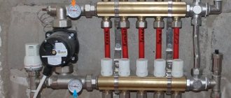
The pump and mixing unit for underfloor heating Valtec Combimix is equipment that ensures a stable water temperature in the secondary circuit (SC). The presence of such a design guarantees the balanced operation of all devices used in the system. In this article we will talk about the features of connecting and configuring such a node.
Device
Several branches can be connected to this model at once, provided that they have a total power of up to 20 kW. The Valtek mixing unit for heated floors is controlled by valves:
- balancing and shut-off (BZ) for the primary circuit (PC);
- balancing for VC;
- bypass;
- drain.
There is also an air vent, thermometers and other auxiliary elements. The BZ valve for PC is used to adjust the volume of coolant. In addition, it is capable of completely blocking the water flow moving into the mixing unit for Valtec heated floors. Control is carried out by unscrewing/tightening the screw. The balancing valve for the VK is responsible for mixing the liquids coming from the manifold and pipeline. It ensures the desired outlet temperature of the mixture.
The Valtec Combimix bypass valve is a safety mechanism in case all other valves suddenly close. In such a situation, it opens a backup path, giving the pump the opportunity to move water idle along a small circuit, thereby protecting the system from an accident. The valve can respond to differences in the range of 0.2-0.6 bar. The critical value is set by turning the knob. According to the instructions for the mixing unit for Valtec heated floors, the task of all other elements is to simplify the operation and maintenance of the system.
Performance characteristics
Pumping and mixing units for heated floors are used to create a circulation system of tubes with a low temperature liquid. Adjustment of a comfortable microclimate is carried out by monitoring the flow of liquid and flow in the return, and the interconnection of the circuits.
The operation of mixing units is carried out in the heating system of floors, walls, open areas, greenhouse and greenhouse soil. The structures are used in conjunction with collectors while maintaining a center-to-center distance of 20 cm. The pumping and mixing unit for heated floors is small in size, which is very convenient when placed in small areas.
Connection
The connection process can be divided into several stages:
- Adjusting the VK balancing valve.
- Setting the pump speed.
- Balancing branches.
- Linking compatibility with other elements that make up the system.
- Adjusting the bypass valve.
- Checking the correct operation of the equipment.
Setting up a Valtec underfloor heating manifold begins with assembly. The pipes are connected using the G1 threaded connection. To connect the secondary circuit collectors, special connectors are used. The circulation pump is installed with the ball valves closed. They must be opened before turning on the device. Before starting testing, make sure that all elements are securely fastened in accordance with the instructions.
Before you begin setting up the mixing unit for the Valtek heated floor, you need to remove the thermal head. The bypass valve is set to maximum, that is, 0.6 bar. The latter is necessary so that the device does not work during further setup. Calculation of the level at which the balancing valve will be set is carried out according to the formula: (water temperature (WT) in the PC pipe minus CT in the return pipe, divided by TT of the VC pipe minus TT on the return pipe) x 0.9. The result you get is what you should display.
At the next stage of adjusting the Valtek heated floor, the pump parameters are adjusted. First of all, we should calculate the pressure drops in subsequent circuits, as well as the coolant costs for the air conditioner. Calculation formulas are indicated in the instructions for the Valtek mixing unit for heated floors. If there is no attachment to the equipment, you can get out of the situation by installing the pump at the minimum level. If during adjustment it turns out that this pressure is not enough, simply increase the speed.
Balancing the branches begins with closing the BZ valve PC. Remove the cover and tighten the screw until it stops, using the appropriate key. The direction is opposite to the clockwise movement. If the adjustment of the Valtec underfloor heating manifold involves connecting to only one circuit, no additional devices will be required. If there are several branches, you need to purchase additional valves or flow regulators.
The process goes as follows. We open the valves/regulators to the maximum and select the branch where the actual flow rate does not correspond most to that specified in the instructions for the Valtec underfloor heating manifold. We adjust this valve to the required level. We do the same with the rest. To indicate flow, it is recommended to use the VT.FLC15.0.0 device. If this indicator is not available, be guided by the temperature of the return carrier of the warm liquid or by the degree of heating of areas of the system. If you cannot organize the correct coolant flow, increase the pump speed.
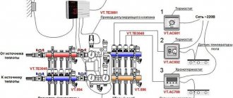
Temperature control
To regulate the temperature regime, a control valve with a thermal head is placed at the inlet part of the unit. The diagram of a pumping and mixing unit for a heated floor indicates the presence of an external temperature sensor placed in front of the supply manifold. The heating of the liquid in the system is set manually using the thermal head scale. When the parameters increase, the valve automatically closes, stopping the flow of hot coolant into the unit. When the water cools, the valve opens access to the hot coolant. This allows for a constant temperature at the outlet of the unit.
To adjust the design ratio between the heated and cold liquid entering the pump inlet, two manual balancing valves are provided. The pumping and mixing unit for a heated floor, installed by yourself, has the first valve on the return manifold. It allows you to adjust the volume of cold coolant supplied to the mixing unit. The second valve is installed at the outlet of the unit, in front of the connection tube to the radiator return circuit. It helps adjust the volume of heated liquid entering the unit.
When the mode is set correctly, the thermostat valve takes the middle position and affects the increase or decrease in the supply of warm water to the unit. The setting facilitates the interconnected operation of the heating circuit with other room systems. In the absence of balancing, the pumping and mixing unit for underfloor heating VALTEC COMBIMIX pumps through itself more liquid than is required by calculation, taking it from other systems.
Final debugging
Adjusting the mixing unit of a Valtek heated floor requires linking the equipment with other heating devices. The main task: to adjust the movement of coolant through each unit so that it corresponds to the project. If mistakes are made at this stage, some devices may not heat up enough, while others, on the contrary, will overheat. There are several ways to balance a Valtec underfloor heating manifold. The instructions for the equipment describe this process in detail.
Next, we have to configure the bypass valve. You can do this in one of two ways. When we know the resistance of the busiest branch, the same value is set. If the indicator is unknown, focus on the pump. In the latter case, the value for the valve should be 90-95% of the maximum pump pressure for the speed at which it is set. The instructions for Valtek water-heated floors also indicate these parameters.
The process ends with a system check. The task is to ensure that all branches are heated evenly and that the correct balance of temperatures of the liquid flowing through all pipelines is maintained. If you are sure that the mixing unit for the Valtec heated floor is configured correctly, you can put on the thermal head of the control valve, as well as other protective attachments. The equipment is now completely ready for use. As you can see, the process is not so complicated that it is necessary to resort to the help of professionals.
Warm floors from Valtek units are a high-quality and reliable system that will provide a comfortable climate in the room for many years. It's no secret that setting up heating is one of the most difficult engineering tasks. The slightest miscalculations at this stage can lead to unstable operation, resulting in user dissatisfaction and reduced equipment life. The operating principle of the Valtec underfloor heating mixing unit greatly simplifies the organization of the system. No special tools are required for installation, and the design diagram virtually eliminates the possibility of making a mistake.
Setting up the VALTEC COMBIMIX pumping and mixing unit
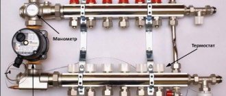
The VALTEC COMBIMIX (VT.COMBI) pump and mixing unit is designed to maintain a given temperature of the coolant in the secondary circuit (due to mixing from the return line). Using this unit, it is also possible to hydraulically link an existing high-temperature heating system and a low-temperature underfloor heating circuit. In addition to the main control elements, the unit also includes the entire necessary set of service elements: an air vent and a drain valve, which simplify the maintenance of the system as a whole. Thermometers make it easy to monitor the operation of the unit without the use of additional devices and tools.
It is permissible to connect an unlimited number of heated floor branches with a total power of no more than 20 kW to the VALTEC COMBIMIX node. When connecting several branches of a heated floor to a node, it is recommended to use VALTEC VTc.594 or VTc.596 collector blocks.
The main adjustment elements of the pumping and mixing unit:
1. Balancing valve of the secondary circuit (position 2 in the diagram).
This valve ensures mixing of the coolant from the return collector of the heated floor with the coolant from the supply pipeline in the proportion necessary to maintain the specified temperature of the coolant at the outlet of the COMBIMIX unit.
The valve setting is changed using a hex wrench; to prevent accidental rotation during operation, the valve is secured with a clamping screw. The valve has a scale with valve throughput values Kvτ from 0 to 5 m3/h.
Note: Although the valve capacity is measured in m3/h, it is not the actual coolant flow rate passing through this valve.
2. Balancing shut-off valve of the primary circuit (pos. 
Using this valve, the required amount of coolant is adjusted that will flow from the primary circuit to the unit (unit balancing). In addition, the valve can be used as a shut-off valve to completely shut off the flow. The valve has an adjusting screw with which you can set the valve capacity. The valve is opened and closed using a hex key. The valve has a protective hex cap.
3. Bypass valve (item 7)
During operation of the heating system, a mode may arise when all control valves of the heated floor are closed. In this case, the pump will operate in a muted system (without coolant flow) and will quickly fail. In order to avoid such modes, there is a bypass valve on the unit, which, when the valves of the underfloor heating system are completely closed, opens an additional bypass and allows the pump to circulate water through a small circuit in idle mode without loss of functionality.
The valve is activated by the pressure difference created by the pump. The pressure difference at which the valve opens is set by turning the regulator. There is a scale on the side of the valve with a range of 0.2–0.6 bar. Pumps recommended for use with COMBIMIX have a maximum pressure of 0.22 to 0.6 bar.
After the heating system is completely assembled, pressure tested and filled with water, it should be adjusted. The adjustment of the control unit is carried out together with the commissioning of the entire heating system. It is best to adjust the unit before starting to balance the system.
Algorithm for setting up the control unit:
1. Remove the thermal head (1) or servo drive.
To ensure that the control valve actuator does not affect the assembly during adjustment, it must be removed.
2. Set the bypass valve to the maximum position (0.6 bar).
If the bypass valve is triggered while the unit is being configured, the setup will be incorrect. Therefore, it should be set to a position in which it will not work.
3. Adjust the position of the secondary circuit balancing valve (item 2 in the diagram).
The required capacity of the balancing valve can be calculated independently using a simple formula:
t1 – coolant temperature on the supply pipeline of the primary circuit;
t11 – temperature of the coolant on the supply pipeline of the secondary circuit;
t12 – coolant temperature in the return pipeline (both circuits are the same);
Kvτ is the control valve capacity coefficient; for COMBIMIX it is assumed to be 0.9.
Calculation example
Initial data: design temperature of the supply coolant – 90 °C; design parameters of the heated floor circuit are 45–35 °C.
The resulting Kv value is set on the valve.
4. Set the pump to the required speed.
To do this, you need to calculate the water flow in the secondary circuit and the pressure loss in the circuits after the unit using the formulas:
G2 = 3600 · Q / s · (t11 – t12), kg/h;
ΔPн= ΔPс + 1, m water. Art.,
where Q is the sum of the thermal power of all loops connected to COMBIMIX; c – heat capacity of the coolant (for water – 4.2 kJ/kg °C; if a different coolant is used, the value should be taken from the data sheet of this liquid); t11, t12 – temperature of the coolant in the supply and return pipelines of the circuit after the COMBIMIX unit. ΔPс – pressure loss in the design circuit of the heated floor (including collectors). This value can be obtained by performing a hydraulic calculation of the heated floor. To do this, you can use the calculation program VALTEC.PRG.
Using the pump nomograms presented below, we determine the pump speed. To determine the pump speed, a point with the corresponding pressure and flow rate is marked on the characteristic. Next, the nearest curve above this point is determined, and it will correspond to the required speed.
Example
Initial conditions: underfloor heating with a total power of 10 kW, pressure loss in the most loaded loop of 15 kPa (1.53 m of water column).
Water flow in the secondary circuit:
G2 = 3600 · Q / s · (t11 – t12) = 3600 · 10 / 4.2 · (45 – 35) = 857 kg/h (0.86 m3/h).
Pressure losses in the circuits after the COMBIMIX unit with a reserve of 1 m of water. Art.:
ΔPн= ΔPс + 1 = 1.53 + 1 = 2.53 m water. Art.
Selected pump speed – MED at point (0.86 m3/h; 4.05 m water column):
If it is not possible to calculate the pump, then you can skip this step and proceed directly to the next one. At the same time, set the pump to the minimum position. If during the balancing process it turns out that there is not enough pump pressure, you need to switch the pump to a higher speed.
5. Balancing the branches of a heated floor.
Close the balancing shut-off valve of the primary circuit. To do this, open the valve cover and use a hex wrench to turn the valve counterclockwise until it stops.
The task of balancing heated floor branches comes down to creating the required coolant flow in each branch and, as a result, uniform heating.
The branches are balanced with each other using balancing valves or flow regulators (not included in the COMBIMIX kit; flow regulators are included in the VTc.596.EMNX manifold block). If there is only one circuit after COMBIMIX, then nothing needs to be linked.
The balancing process is as follows: balancing valves/flow regulators on all branches of the heated floor are opened to the maximum, then a branch is selected in which the deviation of the actual flow from the design one is maximum. The valve on this branch closes to the required flow rate. Thus, it is necessary to adjust all the branches of the heated floor.
When adjusting the VT.FLC15.0.0 flow regulators, you simply need to set the desired flow rate on the scale in l/min by turning the knob. If it is not possible to use a flow indicator, then you can balance the branches approximately by heating the floors or by the temperature of the return coolant.
If during the balancing process it was not possible to obtain the required flow rate through the branches even with the valves open, this means that the hydraulic calculation was performed incorrectly and the pump should be switched to a higher speed.
Setting the primary circuit balancing valve
The balancing valve of the primary circuit is adjusted together with the balancing of the rest of the heating system. The essence of balancing a heating system is to adjust the coolant flow through each heating device, including COMBIMIX, exactly according to the design. If heating systems are not balanced correctly, the system may operate when some of the heating devices are overheated and some are not warmed up enough.
Consider the following diagram of a heating system with a connected COMBIMIX node. This is a two-pipe dead-end heating system with horizontal wiring.
Below the diagram is a piezometric graph. The graph shows the pressure drop in the heating system with green slanted lines. The device located closest to the boiler (or individual heating point) has a greater pressure drop between the forward and return pipelines (vertical lines) than the device located at the end of the system. The orange color on the vertical lines shows the pressure drop across the devices without taking into account the balancing valves, the green color shows the pressure drop that must be created across the valve in order to balance the system. The higher the pressure drop across the device, the greater the flow rate passes through it at the same throughput. In order to equalize the coolant flow in the system, it is necessary to add resistance to devices that are closer to the boiler using balancing valves or control valves. The closer the device is to the boiler, the more resistance must be added using the valve (more valve closing). The graph shows that the valve of the first device is closed so much that its resistance is several times higher than the resistance of the radiator. With the latter device, the valve is practically open and its resistance is low.
Balancing, as a rule, comes down to finding the desired setting of the balancing valves. There are three main ways to perform balancing.
The calculation method consists in the fact that when hydraulically calculating a heating system, a similar piezometric graph is drawn up for the designed heating system. During the hydraulic calculation, the required pressure loss at each balancing valve is determined. Next, the following formula determines the valve capacity:
kv = V /√ΔP, m3/h,
where V is the volumetric flow rate of the coolant, m3/h; ΔP – required pressure loss across the valve, bar.
After calculating the capacity according to the recommendations of the balancing valve manufacturers, the adjuster sets the design capacity value on each valve. Hydraulic calculations must be carried out by a qualified specialist manually or using specialized programs, for example the VALTEC.PRG engineering systems calculation program.
Example
First, let's determine the required coolant flow in the primary circuit. To do this, you can use the following formula:
G2 = 3600 Q /c (t1 – t2),
where Q is the sum of the thermal power of all devices connected after COMBIMIX; c – heat capacity of the coolant (for water – 4.2 kJ/kg °C; if a different coolant is used, the value should be taken from the data sheet of this liquid); t1, t2 – temperature of the coolant in the supply and return pipelines of the primary circuit (the temperatures of the coolant in the return pipeline of the primary and secondary pipelines are the same).
For a heated floor with a total power of 10 kW with a design temperature of the supply coolant of 90 °C, design parameters of the heated floor circuit of 45–35 °C, the coolant flow in the primary circuit will be as follows:
G2 = 3600 · Q /c · (t1 – t2) = 3600 · 10 / 4.2 · (90 – 35) = 155.8 kg/h.
When calculating, the designer determined that the pressure loss on the balancing valve of the unit should be 9 kPa (0.09 bar), in order for the coolant flow in the primary circuit to be 0.159 m3/h, the kv of the valve should be:
kv = 0.159 /√0.09 = 0.53 m3/h.
Next, according to the characteristics of the balancing valve of the primary circuit given below, the number of turns of the adjusting screw is determined.
To determine the number of revolutions, you can not count kv but use the nomogram given below. To do this, plot the required flow through the primary circuit and the required pressure loss across the valve on the graph. The nearest inclined line will correspond to the required setting (number of revolutions). To improve accuracy, you can interpolate the obtained values.
The first line of the table indicates the position, the second line of the table indicates the number of turns of the adjusting screw. (In this example, 2 and ¼.) The third line shows Kv for this setting, as you can see it practically coincides with the calculated one.
Setting the valve speed:
The correct adjustment of the valve should start from the position of the valve being fully closed; using a thin flat-head screwdriver, tighten the adjusting screw until it stops and put a mark on the valve and on the screwdriver.
Using the valve setting table, turn the screw the required number of revolutions. To fix the speed, use the marks on the valve and screwdriver. (following the example, you need to make 2 and ¼ turns).
Using a hex key, open the valve until it stops. The valve will open exactly as much as you turn the screwdriver. After setting the valve, you can open and close it using a hex wrench, while maintaining the capacity setting.
In the same way, all other balancing valves of the heating system are calculated. The number of valve revolutions (or the setting position is determined according to the methods of balancing valve manufacturers).
The second way to balance the system is that the settings of all valves are set “in place”. In this case, the setting values are determined based on the actually measured coolant flow rates for individual branches or systems.
This method is used, as a rule, when setting up large or critical heating systems. During balancing, special devices are used - flow meters, with which you can measure flow in individual directions without opening the pipeline. Balancing valves with fittings and special pressure gauges are also often used to measure the pressure drop, which can also be used to determine the flow rate in individual areas. The disadvantage of this method is that instruments designed to measure flow are too expensive for one-time or infrequent use. For small systems, the cost of the devices may exceed the cost of the heating system itself.
When balancing using this method, COMBIMIX is configured as follows:
Fix the flow meter on the pipeline through which COMBIMIX is connected to the heating system. Calibrate and configure the flow meter according to the instructions for the flow meter.
Then smoothly open the balancing valve using a hex wrench, while recording the change in coolant flow. As soon as the coolant flow corresponds to the design, fix the position of the valve using the adjusting screw.
Example
As for the previous example, the coolant flow rate is first calculated.
For a heated floor with a total power of 10 kW, a design temperature of the supply coolant of 90 °C, and design parameters of the heated floor circuit of 45–35 °C, the coolant flow in the primary circuit will be as follows:
G2 = 3600 · Q /c · (t1 – t2) = 3600 · 10 / 4.2 · (90 – 35) = 155.8 kg/h (0.159 m3/h).
Close the balancing valve completely using the hexagon:
Smoothly open the valve using a hexagon and record the flow rate on the flow meter until the flow rate reaches the design value (in the example, 0.159 m3/h).
After the coolant flow has been established, fix the position of the shut-off valve using the adjusting screw (tighten the adjusting screw clockwise until it stops).
After the adjusting screw is fixed, the valve can be opened and closed using a hexagon, the setting will not be lost.
For small systems in the absence of a design and complex measuring instruments, the following balancing method is acceptable:
In the finished system, turn on the boiler and central pump (or other heat supply source), then close all balancing valves on all heating devices or branches. After this, the heating device that is installed furthest from the boiler (heat supply source) is determined. The balancing valve in this device opens completely; after the device has completely warmed up, it is necessary to measure the temperature difference of the coolant before and after the device. Conventionally, we can assume that the temperature of the coolant is equal to the temperature of the pipeline. Then we move on to the next heating device and smoothly open the balancing valve until the temperature difference between the forward and return pipelines coincides with the first device. Repeat this operation with all heating devices. When the turn comes to the COMBIMIX unit, its adjustment should be carried out as follows: If the coolant temperature in the supply pipeline is equal to the design one, then the balancing valve of the primary circuit should be smoothly opened until the readings on the thermometers of the supply and return pipelines of the secondary circuit are equal to the design ± 5 °C.
If the temperature of the coolant in the supply pipeline during setup of the system differs from the design one, then the following formula can be used for recalculation:
where temperatures with the index “P” are design, and temperatures with the index “N” are adjustment (used for adjustment) values.
Example
Consider the following heating system:
To begin with, all balancing valves are closed.
The heating device that is furthest from the boiler is selected. In this case, it is the rightmost radiator. The radiator balancing valve opens completely. After the radiator has warmed up, the temperature of the forward and return pipelines is recorded.
For example, after opening the valve, the temperature in the supply pipeline was 70 °C, the temperature in the return pipeline was 55 °C.
Then a second device is taken at a distance from the boiler. The balancing valve on this device opens until the temperature in the return pipeline is equal to the temperature of the first ±5 °C.
COMBIMIX setting: design temperature of the supply coolant – 90 °C; design parameters of the heated floor circuit are 45–35 °C. Actual readings taken from thermometers: supply coolant temperature – 70 °C.
Using the formula, we determine the temperature of the coolant in the supply pipeline of the secondary circuit:
We determine the temperature of the coolant in the return pipeline of the secondary circuit:
We open the balancing valve of the secondary circuit until the temperatures on the COMBIMIX thermometers coincide with the calculated ones ± 5 ° C.
Fix the position of the shut-off valve using the adjusting screw (tighten the adjusting screw clockwise until it stops). After the adjusting screw is fixed, the valve can be opened and closed using a hexagon, the setting will not be lost.
Next, configure all remaining balancing valves in the same way.
Bypass Valve Setting
There are two ways to set the bypass valve:
- If the resistance of the most loaded branch of the heated floor is known, then this value should be set on the bypass valve.
2. If the pressure loss on the most loaded branch is unknown, then the bypass valve setting can be determined from the pump characteristics.
The valve pressure value is set to 5–10% less than the maximum pump pressure at the selected speed. The maximum pump pressure is determined by the pump characteristics.
The bypass valve should open when the pump approaches a critical point, when there is no water flow and the pump works only to build up pressure. The pressure in this mode can be determined from the characteristic.
An example of determining the setting value of a bypass valve.
In this example, it can be seen that the pump, in the absence of water movement at first speed, has a pressure of 3.05 m of water. Art. (0.3 bar), point 1; at average speed - 4.5 m water. Art. (0.44 bar), point 2; and at a maximum of 5.5 m water. Art. (0.54 bar), point 3.
Since the pump is set to medium speed, we select the setting on the bypass valve 0.44 - 5% = 0.42 bar.
6. Final stage
After setting up all the components of the COMBIMIX unit, you should put back the thermal head of the control valve and make sure that the control valve is working. Close the cover of the primary circuit balancing valve. The unit is ready for use.
Setting up heating systems is one of the most difficult engineering tasks. The VALTEC COMBIMIX pump and mixing unit allows you to simplify this task. This unit is a ready-made comprehensive solution for organizing a heated floor circuit in heating systems. A well-thought-out configuration of the unit allows you to eliminate errors when designing a particular system. The flexibility of the unit setup allows you to set up underfloor heating systems without the use of special devices.
*article taken from the website VALTEC.ru
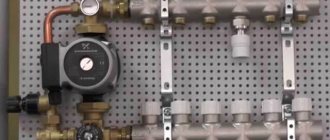
Assembly of the mixing unit
When faced with such a seemingly difficult task, you first need to understand in detail the intricacies of this process. Below is an example of assembling a mixing unit with your own hands; the assembly will be made from metal components.
We will assemble it according to a scheme in which there is a thermostatic three-way mixing valve and a series connection of a circulation pump. To seal the seams, use flax tow and sealant paste; good reviews of Unipack paste.
You will need the following materials:
- Union nuts, American.
- Manual air vent.
- Nipples.
- Circulation pump.
- Thermometer.
- Check valve.
- Ball valve.
- Tees.
We are assembling on the basis of a three-way mixer of the ESBI thermostatic valve; the box indicates in which direction the water is mixed. The operating outlet temperature is 20-43 degrees Celsius, which meets the requirements for a heated floor system. This mixer already contains a thermostatic head, a temperature sensor and a temperature controller that allows you to set the temperature you need. On it itself, arrows indicate in which direction cold and hot water flows.
The next step is to purchase and install a circulation pump. It’s better not to skimp on it and buy a reliable one, since it will determine how evenly the heat will be distributed throughout the house and then the heating will be effective. After all, a pump that is economical in price means in 90% of cases its quick repair or replacement.
Wilo has proven itself well in this niche. Having picked it up, inspect it, determine in which direction it pumps liquid. Determine the direction of the drive axis; during installation, it should be located horizontally; this is one of the mandatory operating conditions for pumps that have a wet rotor installed in their design. Another prerequisite is that the switching box cannot be located under the pump.
If, nevertheless, it becomes this way for you, then rotate the upper element of the housing to which the box is connected 180 degrees. This can be done by using a hex wrench to unscrew the four screws that connect the two halves of the pump. Then carefully rotate the upper element relative to the lower pump element. Put everything back together and tighten the screws.
Photo of an example of a mixing unit for heated floors
The next thing we have to do is to install thermometers on the pipe where the supply takes place before the mixing process, then after the pump. Install the latest one at the outlet of the return manifold. Choose temperature sensors equipped with a probe that screws into central sockets. It would be advisable to verify each device.
Since in one chain they are subject to the same pressure, accordingly, their values should be the same. If possible, check with a reference device. If one of the devices has different readings, you can adjust this yourself. If you remove the cover, you will see a screw that you can use to adjust the readings.
So, the installation steps:
- Assemble the section from the primary supply to the mixing valve, connect the shut-off and ball valves and the tee under the temperature controller. Each of the four taps must be equipped with a union nut. This is done for ease of future maintenance.
- Connect the next outlet of the concentrate to the inlet pipe of the mixer with a three-way valve. Install a thermometer in the central socket of the tee.
- Install a bypass jumper, screw a coupling with an American connection to the second input. This is for ease of installation during maintenance.
- Then connect the tee to the jumper; one side should be facing the return of the system, and the other to the collector.
- The common return element includes one shut-off ball valve. There is no need to install a check valve, since most likely it will not be useful.
- Then assemble a parallel section. Install the temperature sensor by first screwing in the tee.
- Then it was time to assemble the element between the pump and the supply manifold. It includes a coupling with an American connection, a triple connecting element for the temperature regulator, an extension cord, and a shut-off valve.
- Install a ball valve near the manifold.
- Screw the coupling onto the outlet of the mixing valve.
- Well, the almost final stage is the installation of a circulation pump. Insert the rubber O-ring and tighten the nut on the inlet pipe of the pump.
- Screw and crimp the union nut on the other side in the same way. So the mixing unit for the heated floor has been assembled.
This was the final step, then place this element where it will be installed.
Mixing unit structure
The mixing group for heated floors can be built on the basis of a two-way or three-way valve. If the heating system is mixed - with radiators and heated floors, then the unit also contains a circulation pump. Even if the boiler has its own circulation system, it will not be able to “push through” all the loops of the heated floor. That's why they put the second one. And the one on the boiler runs the radiators. In this case, this group is sometimes called a pumping and mixing unit.
Diagram of a three-way valve
A three-way valve is a device that mixes two streams of water. In this case, it is heated supply water and colder water from the return pipeline.
Operating principle of three-way valve
A movable control sector is installed inside this valve, which regulates the intensity of the flow of colder water. This sector can be controlled by a thermostat, manual or electronic thermostat.
The diagram of the mixing unit on a three-way valve is simple: the hot water supply and return are connected to the valve outputs, as well as the output that goes to the supply comb of the manifold for the heated floor. After the three-way valve, a pump is installed that “presses” the water towards the supply comb (the direction is important!). A little further from the pump there is a temperature probe from a thermal head mounted on a three-way valve.
Diagram of a mixing group for a warm water floor on a three-way valve
It all works like this:
- Hot water comes from the boiler. At first, it is passed through the valve without mixing.
- The temperature sensor transmits information to the valve that the water is hot (temperature above the set one). The three-way valve opens the addition of water from the return.
- In this state, the system operates until the water temperature reaches the specified parameters.
- The three-way valve shuts off the cold water supply.
- In this state, the system operates until the water becomes too hot. Then the mixture opens again.
The operating algorithm is simple and understandable. But this scheme has a significant drawback - there is a possibility that in case of failures, hot water will be supplied directly to the heated floor circuits, without mixing. Since pipes in heated floors are laid mainly from polymers, they can collapse if exposed to high temperatures for a long time. Unfortunately, this drawback cannot be eliminated in this scheme.
Please note that in the diagram above the bypass jumper is drawn in green. It is needed in order to exclude the possibility of the boiler operating without consumption. This situation can arise when all shut-off valves on the underfloor heating manifold are closed. That is, a situation will arise when there is no coolant flow at all. In this case, if there is no bypass in the circuit, the boiler may overheat (even overheat for sure) and burn out. If there is a bypass, water from the supply through a jumper (made by a pipe whose diameter is one step smaller than the main one) will be supplied to the boiler inlet. Overheating will not occur, everything will work as normal until flow appears (the temperature in one or more circuits decreases).
Diagram of a two-way valve
A two-way valve is installed on the supply from the boiler. A balancing valve is installed on the jumper between the supply and return pipelines. This device is adjustable, it is adjusted depending on the required supply temperature (usually adjusted with a hex key). It determines the amount of cold water supplied.
A two-way valve must be installed controlled with a temperature sensor. As in the previous scheme, the sensor is placed after the pump, and the pump drives the coolant towards the comb. Only in this case does the intensity of the hot water supply from the boiler change. Accordingly, the temperature of the supplied water at the pump inlet changes (the cold flow is adjusted and stable).
Diagram of a mixing unit based on a two-way valve
As you can see, cold water is always mixed in in this scheme, so in this scheme it is impossible for water to enter the circuits directly from the boiler. That is, the scheme can be called more reliable. But the mixing group on a two-way valve can only provide heating for 150-200 square meters of warm water floors - there are no valves with greater capacity.
Selecting valve parameters
Both two-way and three-way valves are characterized by flow capacity or performance. This is a value that reflects the amount of coolant that it is able to pass through itself per unit of time. Most often expressed in liters per minute (l/min) or cubic meters per hour (m 3 /hour).
In general, when designing a system, it is necessary to make a calculation - determine the throughput of the heated floor circuits, take into account the hydraulic resistance, etc. But if a manifold for a heated floor is assembled with your own hands, calculations are done extremely rarely. More often they are based on experimental data, and they are as follows:
- valves with a flow rate of up to 2 m 3 / hour can provide the required approximately 50-100 sq.m. warm floor (100 square meters - at a stretch with good insulation).
- if the productivity (sometimes designated as KVS) is from 2 m 3 / hour to 4 m 3 / hour, it is fashionable to install them on systems in which the heated floor area is no more than 200 square meters;
- for areas of more than 200 m2, a productivity of more than 4 m 3 / hour is required, but more often they make two mixing units - this is easier.
The materials from which the valves are made are two-way and three-way - brass and stainless steel. When choosing these elements, you should take only branded and proven ones - the operation of the entire heated floor depends on their performance. There are three clear leaders in quality: Oventrop, Esby, Danfos.
| Name | Connection size | Body/Stem Material | Performance (KVS) | Maximum water temperature | Price |
| Danfoss three-way VMV 15 | 1/2″ inch | brass/stainless steel | 2.5 m3/h | 120°C | 146 € 10690 RUR |
| Danfoss three-way VMV-20 | 3/4″ inch | brass/stainless steel | 4 m3/h | 120°C | 152€ 11127 RUR |
| Danfoss three-way VMV-25 | 1″ inch | brass/stainless steel | 6.5 m3/h | 120°C | 166€ 12152 RUR |
| Esbe three-way VRG 131-15 | 1/2″ inch | brass/composite | 2.5 m3/h | 110°C | 52€ 3806 RUR |
| Esbe three-way VRG 131-20 | 3/4″ inch | brass/composite | 4 m3/h | 110°C | 48€ 3514 RUR |
| Barberi V07M20NAA | 3/4″ inch | brass | 1.6 m3/h | adjustment limit – 20-43°C | 48€ 3514 RUR |
| Barberi V07M25NAA | 1″ inch | brass | 1.6 m3/h | adjustment limit – 20-43°C | 48€ 3514 RUR |
| Barberi 46002000MB | 3/4″ inch | brass | 4 m3/h | 110°C | 31€ 2307rub |
| Barberi 46002500MD | 1″ inch | brass | 8 m3/h | 110°C | 40€ 2984rub |
There is one more parameter that needs to be selected - the limits for adjusting the coolant temperature. The specifications usually indicate the minimum and maximum temperatures. If you live in the Middle Zone or further south, during the off-season, a comfortable room temperature is maintained if the lower control limit is 30°C or less (at 35°C it is already hot). In this case, the adjustment limits may look like this: 30-55°C. For more northern regions or with poor floor insulation, take with an adjustment limit of 35 degrees. When assembled, the mixing group is installed in front of the underfloor heating manifold. Then the coolant at the required temperature enters the circuit.
Features of the mixing unit operation
Any liquid heating system works according to the following principle:
- Heating element.
- Heating circuit, pipes through which coolant circulates.
- Devices regulating the coherence of the system.
Liquid heated by the boiler or from the central heating main enters the system. The central heating system supplies water at 60-80 degrees Celsius, while an autonomous heating boiler heats it up to 70-90 degrees. In accordance with sanitary requirements, the floor temperature should be in the range of 29-32 degrees; if these conditions are met, the microclimate in the house will be comfortable for humans.
To achieve these indicators, a liquid of 36-60 degrees enters the water floor. The layers of the floor absorb excess temperature, thereby achieving a comfortable temperature on the floor surface. To transport liquid of the required temperature into the water circuit, a mixing unit is needed, this is a kind of adjustment mechanism.
DIY device
Ready-made mixing units for heated floors are frightening due to their cost, and cheap models are not able to fully provide the required level of comfort and smooth operation. In this case, you can assemble a device with your own hands for automatic or semi-automatic mixing of the return flow with the general current of the hot coolant.
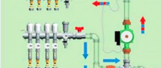
The connection diagram is shown in the figure.
The figure shows:
- Control valve with static thermal head control;
- Balancing valve;
- Circulation pump;
- Immersion thermometer;
- Bypass valve;
- Primary circuit balancing shut-off valve;
- Float automatic air vent;
- Drain rotary valve;
- Ball valve.
T1, T2 – input and output of the primary circuit
T11, T12 – input and output of the secondary circuit, heated floor, collector.
A simple switching diagram does not require the presence of some elements, and the pump is switched on parallel to the heated floor circuits. The regulator is a three-way valve controlled by a thermostatic head.
When choosing a control valve, be sure to check the permissible temperature of the liquid with which it can operate. The requirements for the pump and flow valves, ball valves and drain valves are similar. When assembling the selected circuit, you need to take into account the direction of the coolant flow and, checking it, correctly orient the elements in accordance with the marks on their body.
The thermal head for controlling the control valve must be equipped with a remote thermometer for installation at the outlet of the mixing unit; this is the only way to ensure proper mixing of the hot coolant with the return.
A bypass with a bypass valve allows the circuit to operate adequately even when the hot water supply is completely shut off.
Selection of pump and other system components
Selecting a pump is quite an important step; if you make the wrong choice, you may not achieve the desired results. Naturally, this choice should include several components, namely power, volume, how much energy it consumes and reliability. If you make your choice correctly, you will end up with a warm room and resource savings.
At the first stage, you need to calculate the required power of the pump group, if you have a small heating area, and therefore the pump needs a mini power. According to technical characteristics, they are divided into types with a wet or dry rotor. Power is defined as the total volume of coolant multiplied by three.
However, you also need to take into account such data as the amount of energy consumed, productivity (this is the amount of liquid that it passes through itself per unit of time). Also consider its operating pressure and maximum temperature.
Let's consider the productivity formula provided that the coolant is water:
Q= 0.86*Рн/(Tpr.t-Tobr.t), where -
Рн - heating circuit power;
Tobr.t - return circuit coolant temperature;
Tpr.t - inlet water temperature.
If it is assumed that there is more than one circuit, then the power is summed up, this total will be the required performance value. Power is a value that depends on the heating area; also take into account the climatic factor; if you have harsh winters, it is recommended to take a device with a safety margin of 20-25%.
As for the design of pumps, their selection is based on power; there is a division into devices with a wet rotor and a dry one. Wet ones are designed for small rooms, while dry ones are needed for heating large rooms.
When choosing a boiler, you should also take into account its power and throughput; often a separate boiler is purchased for this. When choosing pipes, pay attention to their wear resistance and ability to bend; it is better to give preference to stainless steel pipes, since they have a high thermal conductivity.
Adjustments and settings
How to set up a heated floor yourself? This question will arise before you as soon as everything is completed with its installation. Install all loops in the distribution manifold. The temperature of the incoming coolant to the collector and loops will be the same. While the output on the loops will be different, this is due to the different lengths of the circuit and different areas.
There are two methods to adjust the floor temperature. The first method is to regulate the fluid that enters the heating circuit. The next method is to regulate the temperature by stopping the circulation of coolant into the heating circuit.
Let's look at all the methods in more detail. One of the methods is to use when installing pipes operating at high temperatures up to 95 degrees. When using this method, a pump and a return outflow valve are installed on the supply, and a temperature sensor is installed on the return manifold.
A pump is connected through it, and a coolant flows into the underfloor heating system, the temperature of which reaches about 80 degrees Celsius. During circulation, the return circulation temperature gradually increases, the sensor is triggered and the supply of warm water is turned off. Then it goes into standby mode. Then the floor gradually gives up its temperature, the coolant cools down and starts all over again.
The next method is to install a pump on the supply, and in front of it a mixing valve; this can be replaced with a three-way valve. With this device, hot and cold water are mixed.
If you have a three-way distribution valve, you need to adjust it manually or using a servo drive. And the mixing valves adjust the temperature values according to preset values. To adjust the valve, you will need to take temperature measurements.
You can also adjust the temperature using the mixing module. They are expensive, however, they are the most effective.
Operating principle of COMBI.S
To work with the weather dependence sensor VT.K200.M, a pumping and mixing unit for heated floors VALTEC COMBI.S has been developed. Instead of the thermal head of the relay valve fluid, an analog servo drive is installed, operating from the controller according to a schedule. For external temperature conditions, appropriate heating of the coolant is provided. This affects the rare operation of room thermostats when opening windows or doors. Floor heating allows you to maintain an accurate calculated level, eliminating fluctuations around the configured indicators from maximum (with the drive open) to minimum. The microclimate comfort is at a higher level.
On COMBI.S units, the temperature regime of the coolant is determined by the controller according to a user-set schedule and sensor data for measuring the level of heating of liquid and air. Similar devices include a pumping and mixing unit for Oventrop underfloor heating.
The circulation pump allows you to speed up the passage of liquid on the return line. Part of it comes from the supply circuit. During the reverse passage, the flow of cooled liquid is divided into 2 parts, approaching the pumping system and the main unit. The ratio of flow directed to the pump and supply is adjusted through valves. If the flow rate of the return pipe does not correspond to the set parameters (the manifold valves are closed), the bypass valve is activated, which is necessary for a constant flow of liquid circulating through the pump. External control of the operation of the unit is carried out by weather-dependent thermal relays.
Schemes and options for connecting mixing units
There are various connection options, almost all of them are homemade, since all calculations and needs of heating points are individual. They differ depending on the number of collectors and the number of circuits, so below are the most commonly used ones.
The node consists of:
- Adapter.
- Circulation pump.
- Ball valves.
- Threaded connection element.
- Futorka.
Futorka - threaded fitting - Barrel.
- Tees.
For an auto-adjustment system, the elements are slightly different:
- Mixing valve.
- Futorka.
- American women.
- Metal-plastic pipes.
- Connecting elements with internal thread.
- Nipple.
- Thermal head.
- Pump nuts.
- The pump itself.
- Knee.
- Extension cords.
- Knee.
- Thermal head sensor.
To connect multiple circuits, the following components are required:
Why do you need a thermal mixer?
The scheme of a combined heating system of a private house may consist of:
- Heating boiler;
- Collector node;
- Heated floor contours;
- Radiator circuits.
The temperature of the water heated by the boiler is 75-95 ° C, while sanitary standards set the figure at 31 ° C as the maximum comfortable temperature of the floor surface for walking on it barefoot. Therefore, direct flow of water into floor circuits is unacceptable. This problem is solved by installing a mixing unit.
The thermal mixer is used to mix hot and already cooled water from a water floor heating system. Thanks to this, the heating circuit functions without deviations.
How the system works
How does the mixing unit work?
Before being distributed into the collector, the hot coolant enters the mixing system, where a thermostat measures its temperature. If the value exceeds the permissible value, the safety valve opens and prevents cold and hot water. When the liquid reaches the desired temperature, the valve stops supplying hot water.
Mixing unit diagram
As a rule, the mixing unit not only provides a comfortable temperature regime, but also serves to raise the pressure level in the circuit, which improves the circulation of the coolant. The mixing unit diagram includes:
- Safety valve;
- Circulation pump;
- Bypass;
- Air outlets;
- Valves for stable operation of circuits (shut-off, drainage).
The mixing unit diagram can have a different design. Schemes with two- and three-way valves are more popular.
Diagram with two-way valve
A thermostat equipped with an infrared sensor is installed on the two-way (supply) valve, which measures the temperature of the liquid entering the heated floors. The water in the mixing system moves in a circle, and the fuse head regulates the valve that opens or closes the passage of hot water. This is how the process of mixing liquids of different temperatures occurs.
Three-way valve in the mixing circuit
The three-way valve is a universal equipment. It performs the functions of both a bypass valve and a bypass. Its peculiarity is that hot water interferes with the return flow inside the housing. This type of unit is equipped with servos, thermostats, and weather-dependent controllers. The latter are capable of checking the temperature outside every 20 seconds. If the temperature of the water that enters the underfloor heating system does not correspond to the desired temperature, the valve automatically turns 45° in one direction or another.
The three-way design, however, is imperfect and has its drawbacks:
- Presence of excess pressure;
- Possibility of hot water inlet;
- Large throughput, leading to significant fluctuations in coolant temperature.
Sudden changes in pressure and temperature can lead to rupture of underfloor heating pipes.
How to assemble a collector?
The Valtec distribution block is manufactured assembled. Flow meters are already installed on the hot tube. There are thermal heads on the cold line, but the product may only have outputs for attaching temperature control devices. They are protected by plastic caps. The manufacturer gives you the opportunity to choose which automation to install: thermal head, servo drive.
Some small elements need to be connected to the collector group:
- On the right, shut-off valves are connected to the tubes. There are 2 of them in the set.
- A float device is connected to the valves to remove air.
- Opposite the air vents, drain valves are connected to the underside of the tubes.
- The ends of the comb are closed with plugs.
We recommend: How to connect a mixing valve for underfloor heating?
A circulation pump and a three-way or two-way valve are separately connected to the comb. These devices must be purchased separately. They are connected on the left to the tube into which the cold coolant flows. Use brass threaded fittings.
The cold and hot circuits are removed from metal pipes that are connected to the boiler or furnace. They are connected via a bypass at the outlet of the collector group. A circulation pump with a temperature sensor is installed between the circuits.
The rotameter is adjusted when testing the heating system. The protective sleeve must be removed from the device. Using the red ring, the upper bushing, set the rotameter to zero.
Next, using the same bushing, install the valve on the o for large rooms, on the o for small rooms. To fix the rotameter parameters, turn the lower ring to the right until it stops.
Return the protective cap to its original place. The rotameter may not have a locking ring. In this case, the pipeline fill indicator is set without fixing. Valve operation must be checked regularly.
Valtek collectors for heated floors are installed with a liquid heating system. The coolant can be water, antifreeze, glycol fillers that do not freeze at low temperatures. If the heating system is not used, then the coolant does not need to be drained.
The number of circuits on the distribution block is 3-12 pcs. If necessary, additional equipment can be connected to them to increase the flow capacity of the coolant to all rooms in the house.
The comb is mounted on the wall or placed in a manifold cabinet. The manufacturer provides a 10-year warranty on the equipment. Service centers are located in St. Petersburg and Moscow. The block will last more than 50 years.
If necessary, the rotameter or thermal head can be replaced without turning off the heating system. When using a programmable thermostat, the operation of the heated floor control unit can be carried out through electronic gadgets.
We recommend: How to choose a wire for a heated floor?
YouTube responded with an error: The request cannot be completed because you have exceeded your quota.
- Related Posts
- What is included in the Valtek heated floor kit?
- How to install underfloor heating on a wooden floor?
- How to lay polystyrene foam for heated floors?
- How does a comb for heated floors work?
- Features of heated floors made of metal-plastic pipes
- What should a laminate be like for a warm water floor?
How to set up a mixing unit?
Connecting the mixing units is quite simple, so installation can be done with your own hands if you have instructions. The first thing to do is choose a location for the mixing unit.
If the parts of the water floor are connected through flexible pipes, then the mixing unit is rigidly mounted on the wall. The parts of the mixing unit must be freely accessible.
Manifold cabinet and its equipment
It is imperative to take into account the type of material from which the pipes are made. They must withstand the temperature of the incoming coolant. If a water-glycol solution is used, galvanized pipes will not work.
After installation, the mixing system is connected to the coolant supply and return pipes and pressure, temperature and flow sensors are installed. These elements are either supplied with the unit or assembled independently. After this, the thermal mixer is connected to the outlet pipes of the heating circuit.
Connection diagram for mixing unit
Before connecting the circulation pump, grounding must be done. Optimal pressure loss parameters are ensured using a balancing valve on the bypass. In this case, losses in the check valve are taken into account.
If the heating system is single-pipe, the bypass must always be in the open position. Then the hot water will flow in parts to the radiators. In a two-pipe circuit, the bypass is closed. When the entire structure is assembled, it is connected to the circuits using fittings.
Description of the elements of the collector group
produces heating equipment for heating systems, radiator and floor. For water heating, a pipe and perforated insulation with fastening elements for the liquid line are purchased.
The pipes are connected to a comb, which consists of supply and return manifolds. What does a Valtec fluid distribution block provide?
- Supply manifold; a line with hot coolant is connected to it.
- The unit is equipped with flow meters that monitor the filling of the floor water circuit.
- An end tube with a float device is used to remove air.
- On the return circuit there are outputs for installing a thermal head. If the head is faulty, it is removed for repair. At the same time, the “warm floor” heating system operates in normal mode, without draining the coolant. The thermal head can be replaced with a servo drive or other control device.
- Flow meter valves; they are not permanently mounted on the hot water bar. A threaded connection is provided for them. If necessary, they can be removed.
- The system is equipped with a float device for air removal. A shut-off valve is connected to it, which allows you to remove the float if necessary.
- A drain valve is designed to remove coolant from the heating system. It has a hinged design.
- To ensure that the installation of the collector block for underfloor heating “Valtec” does not cause difficulties, the equipment kit includes adapter nipples and fittings. They are equipped with heat-resistant rubber gaskets.
- The operating temperature of the comb is 90 0C.
- Optimal pressure 8 bar.
- The filling level of the main line is 2.5 m3/h.
We recommend: How to install Onor heated flooring?
Systems that do not include flow meters are cheaper, but if, along with large rooms, the mains of a bathroom or bathroom that are small in size are connected to the comb, then a device for filling the water circuit is necessary.
Along with a thermal head or servos, it regulates the filling of the water circuit and the room temperature. The flow meter is a valve. It closes, preventing hot water from entering a certain circuit. The device is triggered if the coolant flow exceeds the permissible limit.
The Valtek manifold for heated floors is made of stainless steel or nickel-plated brass. Fittings are made from hot-stamped brass. The air vent float is made of polypropylene.
- The size of the collector group depends on the number of outputs. If the block provides 3 outputs, then the length of the tube is 230 mm. With 7 outlets, the comb has a length of 430 mm.
- The pitch between the outlets is 60 mm.
- Outlet size 1”.
The comb is mounted on the wall using brackets. They have a figured design. The edge that fits tightly to the wall surface is provided for the cold circuit. A tube with hot coolant is fixed on the protruding surface.
Flow meters are located on the supply manifold. The equipment is configured when the circulation pump is turned on. Set the filling level of the highway to 2.5. The temperature parameters on the thermal head should be set before putting the heating system into operation.