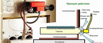
Test of endurance
In most cases, intake fittings (taps, valves, gate valves) are made of metal by casting. During the production of products, the following may form on the body:
- cracks;
- sand or gas sinks;
- porosity;
- heterogeneity of the material.
To identify and eliminate these defects, the shut-off valves are checked for the strength and density of the material used for manufacturing.
How the research is carried out
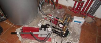
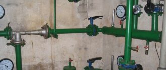
The quality of shut-off valves is carried out using a special stand on which the following are installed:
- a device that supplies water to the fittings and creates a certain pressure. Most often, such a device is a manual or electric pump;
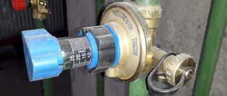
To obtain accurate results, a test pressure is created in the system, which is 1.5 - 2 times higher than the nominal parameter, that is, established by the technical documentation.
Dependence of test pressure on valve parameters
- tested fittings;
- pressure gauge (necessary to determine the pressure in the system);
- 5. 6. control valves required for testing;
- plug complemented by a tube;
- a container of water, a beaker and a special attachment for the beaker.
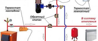
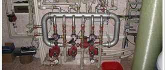
Scheme of a stand for testing material strength
The fittings requiring testing are supplied with water at a set pressure and at normal air temperature. The test time is 25 – 30 seconds (if necessary, the time can be increased). The test results are assessed by external inspection of the product by a qualified specialist.
Test results
The test of shut-off valves is considered successfully passed if it is not detected (in accordance with GOST R 53402-2009):
- mechanical damage and metal deformation;
- leaks;
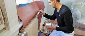
- “sweating” of the metal (protrusion of moisture on the surface of the reinforcement);
Protrusion of moisture on the surface of the reinforcement
drop in pressure gauge readings.
To obtain more accurate results, during the inspection, a specialist can tap the reinforcement product with a small hammer (weighing no more than 1 kg).
How is a technical check performed?
Control pressure testing must be done both before the start of a new gas pipeline and after repairing the old one. Scheduled pressure testing must be carried out before putting the gas pipeline into operation. The same procedure should be repeated during a scheduled check of the condition of the entire system. During the inspection, you will be able to promptly detect any, even the most minor, defects in the pipes. As well as mistakes that could have been made when welding pipes.
Only after all deficiencies have been eliminated is the gas system allowed to be used. It is prohibited to install internal gas pipelines without performing pressure testing - a set of measures aimed at identifying shortcomings.
Before starting the procedure, it is advisable to check the technical condition of the gas pipeline. There are instruments and instructions that will allow you to conduct an examination using technical means. The inspection must be carried out by a trained team consisting of two operators who will be able to examine and evaluate the condition of the entire insulation coating. The third specialist must record places where the seal may be broken.
It is necessary to inspect not only the fittings and main pipes, but also all gas pipes and wells. During the process, you must make sure that there is no gas contamination. If there is a leak, the gas pipeline must be declared emergency, and then troubleshooting must begin. All these manipulations must be carried out during scheduled maintenance of the internal gas pipeline.
Pipeline testing
"First Installation Company" provides services for hydraulic and pneumatic testing of pipelines for strength, density and tightness. After completing the installation of a process pipeline, it is always necessary to carry out tests before putting it into operation. Our company tests both pressure and non-pressure pipelines.
Testing process pipelines for strength takes little time, since exposure to test pressure usually does not take more than 20 minutes. Testing process pipelines for density and tightness takes more time and is usually regulated by the project. Typically this time ranges from half an hour to several hours. An integral part of the installation of process pipelines are hydraulic and pneumatic tests, and in the case of pressure pipelines, these tests are mandatory.
Before testing, the pipeline is degreased and purged with gas to dry it, and purge is also carried out after hydraulic testing of the pipeline to dry residual water.
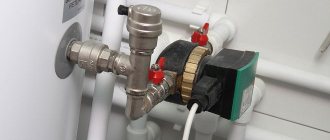
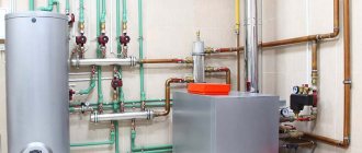
Hydraulic testing of pipelines
Hydraulic tests are carried out if the installed pipeline has high operating pressure (over 50 bar). Pressure is raised in the process pipeline during hydraulic tests using manual or electric pumps.
The hydraulic testing process has several stages:
- connection to the process pipeline circuit of a hydraulic pump;
- installation of pressure gauges at the inlet and outlet of the circuit;
- filling the process pipeline with purified water;
- creating test pressure with a hydraulic pump;
- maintaining the process pipeline under the required pressure;
- releasing pressure to operating level, followed by inspection of the tested section of the pipeline for leaks;
- releasing pressure to zero and draining water from the process pipeline;
- removal of equipment (hydraulic pump, plugs and pressure gauges);
- drying the process pipeline with gas.
The process pipeline is considered to have passed hydraulic tests if the pressure drop did not exceed ten percent of the test pressure, or was not recorded at all. No leaks or sweating were detected in welds or flange connections. If the results are unsatisfactory, the detected defects are eliminated and the test is repeated.
Hydraulic tests of process pipelines in the cold season and in the presence of negative temperatures are carried out, ensuring everything necessary for the non-freezing of water.
Hydraulic tests of water supply pipelines, like hydraulic tests of free-flow pipelines, are carried out with minimal pressure to check the strength and tightness of the connections. Pressure pipelines are tested at the pressure specified by the design.
Pneumatic testing of pipelines
Pneumatic testing of process pipelines is carried out at a low operating pressure of the pipeline, which saves time on drying after testing. For some objective reasons, it is impossible to carry out hydraulic tests, or the project provides for pneumatic tests of pipelines.
Pipelines must be tested under the supervision of the facility manager in accordance with the design and compliance with safety regulations.
Pneumatic tests of process pipelines are usually carried out as a single circuit, together with fittings (with the exception of valves for relieving excess pressure). If the design of the pipeline does not allow this or the design provides otherwise, then the pipeline is divided into conditional lines or sections and each section is tested separately. Pressure gauges must be installed at the gas supply point for testing and at the end of the process pipeline; all leaks must be plugged with special plugs.
Pressure gauges used in pipeline testing must be verified. The accuracy class of pressure gauges must be at least 1.5 and the body diameter must be at least 100 mm, as well as a scale exceeding the test pressure.
Objects for crimping and algorithm of actions
The air test is carried out in the following cases:
- when installing internal and external gas pipelines, equipment, tanks, filling gas tanks;
- after assembling gas control points and installations;
- after replacing or repairing gas pipes or devices, as well as connecting new ones.
Pneumatic testing of a gas pipeline for density and strength is strictly regulated.
- The section of the gas line being studied is turned off. To do this, turn off the high pressure valve. Tighten the low valve and install plugs at the ends of the circuit.
- If a rupture of flange connections is detected, jumpers are installed.
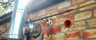
- Connect the rubber-fabric sleeve and release the gas to a safe place. If possible, burn.
- The pipe is purged and a pressure gauge and compressor are installed. If the area is small, you can get by with a hand pump.
- The compressor pumps air under the required pressure. After this, testing begins.
When performing pressure testing, all shut-off devices on the air mixture supply must be closed.
Pneumatic testing of gas pipelines
Posts: 12 Registered: 10/01/12
Good afternoon Give some advice to a newcomer to the gas service.
When installing internal and external gas supply (for standard and non-standard connections), price E16-8-1 is applied - laying gas supply pipelines from steel pipes DN15 mm (well, other diameters, respectively) + additional price E19-15-1 - Pneumatic testing of gas supply pipelines - This is how the previous estimator used it, and I prove that we are doubling the work, which in E16-8-1 is already included in the “Blowing with compressed air” work.
For repairs, accordingly, also the price is p15-141-1 - pipe laying + p15-153-1 - pneumatic test.
I also found a handwritten statement (apparently on the basis of which an additional pneumatic test was taken):
1) “Underground steel and polyethylene gas pipelines of all pressures, as well as above-ground and internal steel gas pipelines of low and medium pressure are tested for strength and tightness with air.” 2) “Crimping (saponification of joints, pumping up pressure) = pneumatic test (saponification, blowing out debris, scale) 3) “Purge is not included in the pneumatic test (done when the gas pipeline is tested)
Tell me who is right and on what basis? (maybe it was somewhere in the Central Organ or some other reliable sources?
Messages: 4475 Registered: 12/06/07
Messages: 1204 Registered: 11/16/10
Posts: 88 Registered: 02/05/08
Posts: 158 Registered: 05/29/15
We have a gas pipeline that was built 1.5-2 years ago, but has not been put into operation. It is necessary to repeat the pneumatic test of the gas pipeline. Gas pipeline internal and external.
I didn’t make the construction estimate, but I have one. Internal gas pipeline: 15,20,25 and 50 (collector) diameter. the following standards were applied: E16-8-1(2.3) - for 15,20 and 25 diameters, and for 50 - E16-9-12. For these positions, a pneumatic test was separately included - E19-15-1 for 15,20,25 diameters, and for 50 diameters there was also a pneumatic test + to the norm a compressor (SN205-102) with machine hours half less than man .hour.
1. How to take pneumatic test? for these diameters? Just E19-15-1? 2. and what to do with this 50 diameter (internal)? And is it possible to add a compressor to the norm where man-hours are calculated to use a hand pump?
Through a street gas pipeline. diameters: 57,76,89 and 108 standards that were used - EN22-9-1 (2,3) There is already a pneumatic test as part of the work. 3. How can the pneumatic test be applied to these diameters? I saw somewhere that they take the same standard as for laying steel pipes, but using a coefficient. 0.1 to the labor costs of builders and 0.3 to the operation of machinery and mechanisms. Maybe it was somewhere in the central heating center?
__________________________________________________________________________________ and further. valve replacement work. diameter 32mm I use RN16-26-1 - this is Installation of steel valves and check valves with a diameter of up to 50 mm, but after installing the valve, a pneumatic test of a gas pipeline with a diameter of 32mm is necessary. What to use for testing?
Working with a hose
You can connect the gas stove yourself using a rubber flexible hose, which is used most often for the following reasons:
- It is quite safe, because thanks to it the stove model can be moved in the kitchen up to 1.5 meters.
- If you accidentally touch the slab and move it from its place, then this will not threaten you in any way.
- This type of connection is considered very durable, because such hoses can last up to 10 years.
- Their cost will be affordable for every owner.
So, let's get to work. Select the length of the hose according to your own preferences, but it is better to take a long product (from 3 m). Be sure to pay attention to the color of the mark on the pipe - you need a braided hose with a yellow mark, because the other colors (red and blue) indicate that this product is intended for water. Such hoses are absolutely not suitable for you, because to connect a gas stove you need a special hose. Now see if the size of the inlet on the hose matches the size of the inlet on the pipe. If the hose outlet does not match the dimensions of the pipe outlet, then buy an adapter.
Safety measures when connecting newly built gas pipelines to existing ones
Work on connecting newly built gas pipelines to existing ones must be carried out in accordance with the “Safety Rules in the Gas Sector”, the rules of technical operation and safety in the gas sector, in force in the republic or department. In accordance with the listed rules, work on connecting newly built gas pipelines to existing ones is permitted to a specialized team subordinate to the management, trust, office operating the gas sector of the city (settlement). The team leader is appointed from among the engineering and technical workers who have been trained in the rules for conducting hazardous gas work and have passed exams to test their knowledge of these rules.
The connection of newly built gas pipelines to existing ones is carried out under special permits from the trust management, the gas industry office, on the basis of acts of acceptance of the gas pipeline for operation. An organization presenting a newly installed gas pipeline for connection transfers technical documentation to the management, trust, gas industry office, including diagrams of the connected gas pipelines indicating all branches, pipe diameters, valves, condensate collectors and other structures.
Before tie-in, underground and above-ground gas pipelines, regardless of operating pressure, are subject to control pressure testing with air to a pressure of 2000 mm water. Art. The pressure drop should not exceed 10 mm water. Art. at 1 o'clock
Tapping into an existing gas pipeline is carried out with or without reducing gas pressure. With reduced pressure during tapping, a pressure of 40 to 100 mm of water is maintained in the gas pipeline. Art. A pressure gauge is installed to monitor pressure. Tapping into existing gas pipelines without reducing the gas pressure in them is allowed when using a special device that prevents gas from escaping outside.
Before starting work, the team leader familiarizes all workers with their responsibilities and the sequence of operations for connecting gas pipelines, then re-instructs the workers on the safety precautions for the work performed by each team member at the site.
The team leader checks the presence of excess air pressure in the connected gas pipeline, the suitability of the pit for tie-in work, the presence and serviceability of shut-off devices at the inlets and risers, taps, valves, plugs and plugs at the gas inlets into the room.
All valves and taps must be closed and plugged. Plugs installed on gas pipelines are designed for the maximum gas pressure in the gas pipeline. They must have shanks that extend beyond the flanges.
The connection of inlets to existing gas pipelines is permitted only when the in-house gas pipelines are disconnected after a valve, a tap at the inlet with the installation of a plug, and in the presence of a device (plug, tap) for releasing air and the gas-air mixture from the underground part of the gas pipeline.
Newly constructed gas pipelines are connected to existing ones using welding, without it - to disconnecting devices installed in advance when laying street gas pipelines. It is possible to connect using welding to gas pipelines of low, medium and high pressure at reduced gas pressure; without reducing the pressure and after disconnecting the existing gas pipeline and completely emptying it of gas.
Connection at reduced pressure is associated with a disruption in the gas supply to a significant number of consumers, so work is carried out at night, as a result of which safety conditions are violated.
Drawings for this chapter:
| A device for connecting branches to existing gas networks without reducing gas pressure |
Norms and rules for crimp testing
Control testing of internal gas pipelines is regulated by GOST R 54983 2012. The general rules are the same for testing any part of the circuit under high and low pressure.
- Pressure testing of gas equipment and pipelines with air is carried out before the line is cut into the central main.
- To check, air is pumped into the cut-in section of the gas pipeline under a pressure of 100 kPa and held for at least 60 minutes. Measure the pressure in the circuit with a pressure gauge. The accuracy class of the device must be less than 0.6.
- If the circuit is sealed, the excess pressure indicator remains until the end of the pressure test. If the pressure gauge records a decrease in pressure, there is a leak in the pipe. According to SP 62.13330.2011, the pressure test is repeated six months after the control test.
For pressure testing, air or inert gas is used.
In an apartment building
Pressure testing of the internal gas pipeline inside the house is carried out after an external inspection. After servicing, the gas pipeline is checked for strength. Air is pumped into the circuit at a pressure of 1 kgm/sq. see. This is how they check the pipeline from the switch at the entrance to the house or to the landing to the taps at the outlets to the devices. A complex gas pipeline is checked by dividing it into separate sections.
If gas meters are installed in the building, during pressure testing they are turned off and the sections are connected by a jumper. The test begins 3 hours after the pressure rises. The possibility of leakage is checked with a soap solution. If defects are identified, the commission records them.
Pressure testing of internal gas pipes includes a density test.
- The gas pipeline is filled with air under a pressure of 400 mm water column. with running meters and gas appliances. If there are no meters in the circuit, air is pumped under a pressure of 500 mm of water. Art. The gas supply system has passed the test if within 5 minutes the pressure drop does not exceed 20 mm of water. Art.
- When connecting new gas equipment to a gas pipeline already operating in an apartment building, pressure testing is carried out with gas. The emulsion is applied to all broken and threaded connections to check for leaks.
- Automation devices are checked only for density. The air pressure during pressure testing reaches 500 m of water. Art.
Covering up defects of any type with putties is strictly prohibited.
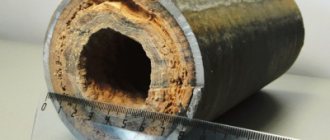
Underground gas pipeline
Pressure testing of an underground gas pipeline is carried out after installation in trenches and full or partial backfilling - at least 20 cm. Each section of the line, from plug to plug, is checked separately.
- Tests begin with air injection under test pressure. Maintain the time required to equalize temperatures.
- Measurements are performed with pressure gauges with an accuracy class of 0.4 or 0.6.
- A section of steel and polyethylene gas pipelines is pressurized separately.
- Pressure testing of underground external gas pipelines placed in cases is carried out three times. For the first time immediately after welding and before laying. Then after backfilling in the trench and finally along with the entire gas pipeline.
- Inspection of multilayer pipes is carried out in 2 stages. First, they are tested for strength by pumping air for 10 minutes at a pressure of 0.1 MPa, and then tested for tightness under a pressure of 0.015 MPa.
Testing of special technical devices is carried out according to the standards for lines with the same pressure.
Internal low pressure gas pipeline
Pressure testing of equipment and internal gas pipelines is carried out with an air mixture under a pressure of 1000 mm of water. Art. The area to be examined is from the main tap to the switch in front of the burners. Testing lasts 1 hour. During this time, a pressure reduction of 60 mm of water is allowed. Art.
Pressure testing in an apartment building includes inspection and testing of household equipment.
- A pressure-vacuum gauge and any device with a variable volume will be connected to the nozzle of the gas stove. With its help, an excess pressure of up to 5 kPa is created.
- Open the tap of the burner being tested and fill the tank with gas.
- Close the valve on the gas pipe. Gas is squeezed out of the container to create pressure.
- Close the burner valve and check the tightness with a vacuum gauge: in 5 minutes the pressure can drop by no more than 0.3 kPa.
- If the pressure drops faster, there is a leak. It is detected by applying a soap solution to joints and threaded connections. Once a leak is detected, turn the valve on the burner so that the gas pressure on it drops. Then light one of the burners, carefully squeeze the gas out of the container and disconnect the pressure gauge and device.
The admissions committee records the test results in the acceptance certificate.