About installing additional units
As a rule, in a closed or open radiator heating system, where the heat source is a single boiler, it is enough to install one circulation pump. In more complex schemes, additional units are used for pumping water (there may be 2 or more of them). They are placed in the following cases:
- when more than one boiler installation is used to heat a private house;
- if a buffer tank is involved in the piping scheme;
- the heating system has several branches serving various consumers - radiators, heated floors and an indirect heating boiler;
- the same, using a hydraulic separator (hydraulic arrow);
- for organizing water circulation in underfloor heating circuits.
Correct wiring of several boilers operating on different types of fuel requires that each of them have its own pumping unit, as shown in the diagram for the joint connection of an electric and TT boiler. How it functions is described in our other article.
Connecting an electric and TT boiler with two pumping devices
In a circuit with a buffer tank, it is necessary to install an additional pump, because it involves at least 2 circulation circuits - boiler and heating.
The buffer tank divides the system into 2 circuits, although in practice there are more of them
A separate story is a complex heating scheme with several branches, implemented in large cottages with 2-4 floors. Here, from 3 to 8 pumping devices can be used (sometimes more), supplying coolant floor by floor and to different heating devices. An example of such a circuit is shown below.
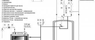
Finally, a second circulation pump is installed when heating the house with water-heated floors. Together with the mixing unit, it performs the task of preparing coolant with a temperature of 35-45 ° C. The operating principle of the circuit presented below is clearly described in this material.
This pumping unit forces coolant to circulate through the heating circuits of underfloor heating.
Reminder. Sometimes pumping devices do not need to be installed for heating at all. The fact is that most electric and gas wall-mounted heat generators are equipped with their own pumping units built inside the housing.
The difference between a two-pipe heating system and a single-pipe one
Let's first define what kind of beast this is - a two-pipe heating system. It’s easy to guess from the name that it uses exactly two pipes; but where do they lead and why are they needed?
The fact is that to heat a heating device with any coolant, it needs circulation. This can be achieved in one of two ways:
- Single-pipe circuit (so-called barracks type)
- Two-pipe heating.
In the first case, the entire heating system is one large ring. It can be opened by heating devices, or, which is much more reasonable, they can be placed parallel to the pipe; the main thing is that there is no separate supply and return pipeline passing through the heated room.
Or rather, in this case these functions are combined by the same pipe.
What do we gain and what do we lose in this case?
- Advantage: minimal material costs.
- Disadvantage: large variation in coolant temperature between the radiators at the beginning and end of the ring.
The second scheme - two-pipe heating - is a little more complicated and more expensive. There are two pipelines running through the entire room (in the case of a multi-storey building - at least on one floor or in the basement) - supply and return.
According to the first, the hot coolant (most often ordinary process water) is sent to the heating devices to give them heat; according to the second, it is returned.
Each heating device (or a riser with several heating devices) is placed in the gap between the supply and return.
There are two main consequences of this connection scheme:
- Disadvantage: the pipe consumption is much higher for two pipelines instead of one.
- Advantage: the ability to supply coolant to ALL heating devices at approximately the same temperature.
Advice: in case of a large room, it is necessary to install a control throttle on each heating device.
This will allow you to equalize the temperature more accurately, making sure that the flow of water from the supply to the return on nearby radiators will not “sag” those more distant from the boiler or elevator.
Dependent open heat supply system
The main feature of the dependent system is that the coolant flowing through the main networks directly enters the house. It is called open because coolant is taken from the supply pipeline to provide the house with hot water. Most often, this scheme is used when connecting multi-apartment residential buildings, administrative and other public buildings to heating networks. The operation of the dependent heating system circuit is shown in the figure:
When the temperature of the coolant in the supply pipeline is up to 95 ºС, it can be sent directly to the heating devices. If the temperature is higher and reaches 105 ºС, then a mixing elevator unit is installed at the entrance to the house, whose task is to mix the water coming from the radiators into the hot coolant in order to lower its temperature.
The scheme was very popular during the Soviet era, when few people were concerned about energy consumption. The fact is that the dependent connection with elevator mixing units works quite reliably and requires practically no supervision, and installation work and material costs are quite cheap. Again, there is no need to lay additional pipes to supply hot water to houses when it can be successfully taken from the heating main.
But this is where the positive aspects of the dependent scheme end. And there are many more negative ones:
- dirt, scale and rust from the main pipelines safely enter all consumer batteries. Old cast-iron radiators and steel convectors didn’t care about these little things, but modern aluminum and other heating devices definitely don’t;
- Due to a decrease in water intake, repair work and other reasons, a pressure drop in the dependent heating system, or even water hammer, often occurs. This has implications for modern batteries and polymer pipelines;
- The quality of the coolant leaves much to be desired, but it goes directly to the water supply. And, although the water in the boiler room goes through all stages of purification and desalting, kilometers of old rusty mains make themselves felt;
- Regulating the temperature in rooms is not easy. Even full-bore thermostatic valves quickly fail due to poor quality coolant.
Two-pipe heating system, types and advantages
The main difference between such a heating system is that it consists of two pipelines: supply and return. Through the supply, the coolant heated in the boiler is transported and distributed to the heating devices. The return line carries the coolant back to the boiler. The greater efficiency of a two-pipe system over a single-pipe system is ensured by the fact that the coolant is distributed among all heating devices (radiators) at the same temperature, when in a single-pipe system it passes through all devices sequentially, while gradually losing all the received heat when approaching the last radiator.
There is an opinion that double the length of pipes will cause high costs when purchasing them. This is partly incorrect, because a two-pipe system does not require pipes as large in diameter as a one-pipe system. The use of large pipeline diameters in a single-pipe system is determined by the fact that it is necessary to minimize the resistance when the coolant passes through the pipeline. The dimensions of valves, connections, fasteners, and fittings used in two-pipe systems are also correspondingly smaller than in single-pipe systems. Therefore, as a result, the benefit when purchasing materials for a single-pipe system will not be so great.
Another advantage of heating with two lines is that you can install a thermostat near each heating radiator, which will allow you to regulate the flow of coolant through the battery and reduce heating costs. It is also important that the smaller diameter of the pipelines does not spoil the overall interior of the room, and it is much easier to hide pipes in building structures. In view of all these advantages, it is logical that a two-pipe system is more often used for heating a house, however, there are several types of such a system, so you should choose the type that is most suitable in this case.
Pros of independent systems
Already at the approach to the main consumers of the home water supply network, a whole range of preparatory measures is provided to ensure distribution, filtration and adjustment of coolant pressure. All loads fall not on the final equipment, but on the heat exchanger with a hydraulic tank, which directly receive resources from the main source. Such resource preparation is practically impossible on a private basis when operating dependent heating systems. Connecting an independent circuit also allows you to rationally use water for drinking needs for optimal purification. Streams are divided according to their intended purpose and each line can provide a separate level of preparation that meets technological requirements.
Disadvantages of dependent heating systems
Among the negative aspects of operating such systems, the following are noted:
- Intensive contamination of working circuits with scale, dirt, rust and all kinds of impurities, which may well end up in consumer equipment.
- Higher requirements for carrying out repair activities. The fact is that dependent and independent heating systems in such cases require the involvement of specialists of different levels. It is one thing to carry out repairs on the main line once a year, and another to carry out a comprehensive monthly inspection of the elevator assembly piping at home.
- Water hammer is possible. Incorrect connection of communications or excessively high pressure in the circuit can lead to pipe ruptures.
- Low basic quality of the coolant in composition.
- Difficulties in control and management. At technological stations of municipal water heating, the process of updating the same shut-off valves is quite slow, hence disturbances in pressure balances may occur.
Useful tips
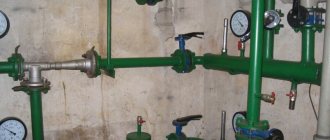
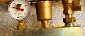
To prevent arbitrary changes in water flow, shut-off valves are attached to the inlet-outlet area of the circulation pump. The connecting nodes must be treated with a “sealant”, this will increase the performance of the entire heating system.
To quickly and correctly install a pump pump, you need selected connections and threads. To reduce the time spent searching for all the necessary parts, look in plumbing stores for a special device with already selected fasteners. After completing the installation process of the pumping unit, the system is filled with water or other coolant.
Before starting the system, you should open the central valve to remove air pockets - the appearance of water will indicate the complete removal of air from the system.
About quantity and breakdowns
The number of circulation pumps required to heat a private house can be determined based on the entire length of the pipeline. If its length is about 80 m, then one is enough. If this length is exceeded, you need to consider increasing the number of pumps in the system.
The reasons for the failure of circulation pumps can be incorrect installation, arbitrary placement of the cable connections and terminal module, as well as non-compliance with the operating rules of the heating boiler
To avoid malfunctions, it is important not to ignore the procedures for regular air release and take care to thoroughly clean the system from mechanical particles
But it should be remembered that all breakdowns of the circulation pump must be corrected by specialists. Therefore, if faults have already appeared and are detected, then it is best to contact the repair service.
Possible reasons why return pipes are cold or too hot
If there is insufficient heating of the premises, you should look for problems in the heating system, and it is useful to know how to determine the supply and return taps; the cold temperature of the latter indicates a malfunction in the heating circuit. In this case, the operation of all automatic systems and thermostats associated with responding to the temperature parameters of the output coolant is disrupted - this can lead to a malfunction of the entire system.
The main causes of cold return pipes are:
Installation errors. A similar situation can most likely occur when panel steel radiators that have two built-in terminals with a standard axial size are installed at the bottom using special units. In addition to the fact that their built-in radiator channels are designed to connect only their supply or return line, the correct operation of the units themselves becomes impossible if the pipes suitable for them are mixed up, the type of which is indicated by arrows on the device body.
Airing. The presence of air in any risers, pipelines or radiators leads to malfunctions of the system, in which an insufficient amount of coolant is supplied to the heat exchangers, as a result of which the temperature of the exiting liquid will be too low.
Rice. 14 Return pipeline in the collector distribution
Reducing the channel cross-section. In case of mechanical defects, contamination of the channels as a result of the use of hard water or expired antifreeze, in which the cross-section is narrowed, the volume of coolant entering the heater is too small and the return will have a low temperature. Often the narrow passage channels of shut-off plumbing fittings become clogged - in this case, the tap must be dismantled and cleaned with a means to remove lime deposits or other decomposition products.
Equipment breakdowns. Failure of the circulation pump will lead to the cessation of fluid flow, cooling of all circuits and cold return; this problem can occur from insufficient fluid flow in the line, which occurs when the circulation electric pump is faulty or insufficiently powerful. In case of mechanical damage or loosening of compression couplings, depressurization occurs, coolant leaks out and, accordingly, the entire system loses its functionality.
Technological reasons. In forced circuits, the movement of the coolant is carried out using an electric pump; when it is turned off due to lack of electricity, the movement of the liquid and the heating of the premises stop, the electric boiler also does not work and the batteries remain cold. If the supply of fuel to a gas heating boiler or diesel fuel is cut off, the house will also be left without heating.
Rice. 15 Violations when soldering polypropylene
Overfeeding
Reducing the flow helps to reduce the temperature of the return line, there are several reasons for this, in addition to clogging of the main passage due to contamination, narrowed channels in the places where the shut-off valves of control valves are located, in branches with connected auxiliary devices, such as liquid meters or thermostats, are often clogged.
In many cases, the determining factor for low flow is gross errors in installation, and you need to pay attention first of all to technology violations associated with soldering polypropylene pipes by inexperienced specialists. When the surfaces overheat during joining, the molten polyprolene is pressed into the pipe shell and the passage channel is narrowed, leading to insufficient heating of all heaters and a cold return.
If there are blockages, you will need to flush the system with hot liquid and resolder all joints if the polypropylene pipes are connected incorrectly.
Rice. 16 Clogged heating pipe
Poor coolant circulation
Poor circulation is often found in open gravity systems; it occurs when there is insufficient temperature difference between the medium at the inlet and outlet of the boiler. In a closed circuit, if operational problems arise, its low speed is associated with poor operation of the circular electric pump, clogging of the channel and fittings with limescale, and antifreeze decomposition products.
It may be necessary to flush parts of the system and drain the coolant; in case of severe contamination, individual devices (pump, hydraulic valve, three-way valve) are removed and cleaned separately. On the circulation pump, you should select a higher rotation speed of the electric motor shaft with an impeller (the standard device contains 2 or 3 speeds).
Return coolant overheating
Sometimes a situation arises when the average temperature of the return water is too high; this phenomenon can lead to a malfunction of the system, the mode of which is associated with measuring the temperature of the medium in the line. The main reasons for this phenomenon are too high a rate of water circulation through the heating circuit and flow through the bypasses of single-pipe systems connecting the supply and return pipelines. Since the carrier transfers heat with low efficiency, transferring it to radiators in too large a volume or bypassing them via the bypass jumper, this phenomenon leads to unjustifiably increased energy consumption and a decrease in the efficiency of the entire system.
To eliminate the negative consequences of overheating in a private house, reduce the rotation speed of the centrifugal wheel of the circulation pump, reduce the heating temperature of the working fluid, narrow the bypass passage channel, installing pipes of a smaller cross-section or installing control valves in each of them; similar operations with bypass are carried out in apartment buildings .
Rice. 17 How to choose a connection scheme from an efficiency point of view
To implement heating in private houses, one-pipe and two-pipe systems are used, the former are the most cost-effective, and the latter ensure uniform heating of all heat exchangers when using a Tichelman loop. It should be noted that the return of the heating system plays an important role: its correct installation increases the efficiency of the system, and temperature parameters are used in the operation of automatic devices that optimize heating and increase efficiency, as well as in identifying faults.
Where to put
It is recommended to install a circulation pump after the boiler, before the first branch, but on the supply or return pipeline it doesn’t matter. Modern units are made from materials that can withstand temperatures up to 100-115°C. There are few heating systems that work with a hotter coolant, so considerations of a more “comfortable” temperature are untenable, but if you feel safer, put it in the return line.
Can be installed in the return or direct pipeline after/before the boiler up to the first branch
There is no difference in hydraulics - the boiler, and the rest of the system; it makes absolutely no difference whether there is a pump in the supply or return branch. What matters is the correct installation, in terms of strapping, and the correct orientation of the rotor in space
Nothing else matters
There is one important point regarding the installation location. If the heating system has two separate branches - on the right and left wings of the house or on the first and second floor - it makes sense to install a separate unit on each, and not one common one - directly after the boiler. Moreover, the same rule remains on these branches: immediately after the boiler, before the first branch in this heating circuit. This will make it possible to set the required thermal conditions in each part of the house independently of the other, and also in two-story houses to save on heating. How? Due to the fact that the second floor is usually much warmer than the first floor and much less heat is required there. If there are two pumps in the branch that goes up, the speed of movement of the coolant is set much lower, and this allows you to burn less fuel, without compromising the comfort of living.
There are two types of heating systems - forced and natural circulation. Systems with forced circulation cannot work without a pump; systems with natural circulation work, but in this mode they have lower heat transfer. However, less heat is still much better than no heat at all, so in areas where electricity is often cut off, the system is designed as hydraulic (with natural circulation), and then a pump is installed into it. This gives high heating efficiency and reliability. It is clear that the installation of a circulation pump in these systems is different.
All heating systems with heated floors are forced - without a pump, the coolant will not pass through such large circuits
Forced circulation
Since a forced circulation heating system without a pump is inoperative, it is installed directly into the gap in the supply or return pipe (of your choice).
Most problems with the circulation pump arise due to the presence of mechanical impurities (sand, other abrasive particles) in the coolant. They can jam the impeller and stop the motor. Therefore, a mesh dirt filter must be placed in front of the unit.
Installing a circulation pump in a forced circulation system
It is also advisable to install ball valves on both sides. They will make it possible to replace or repair the device without draining the coolant from the system. Turn off the taps and remove the unit. Only that part of the water that was directly in this piece of the system is drained.
Natural circulation
The piping of the circulation pump in gravity systems has one significant difference - a bypass is required. This is a jumper that makes the system operational when the pump is not working. One ball shut-off valve is installed on the bypass, which is closed the entire time the pumping is running. In this mode, the system operates as forced.
Installation diagram of a circulation pump in a system with natural circulation
When the electricity goes out or the unit fails, the valve on the jumper is opened, the valve leading to the pump is closed, and the system operates as a gravity system.
Installation features
There is one important point, without which the installation of the circulation pump will require rework: it is necessary to rotate the rotor so that it is directed horizontally. The second point is the direction of flow. There is an arrow on the body indicating which direction the coolant should flow. This is how you turn the unit so that the direction of movement of the coolant is “in the direction of the arrow”.
The pump itself can be installed both horizontally and vertically, just when selecting a model, make sure that it can work in both positions. And one more thing: with a vertical arrangement, the power (pressure created) drops by about 30%. This must be taken into account when choosing a model.
Circulation pump connection
If the pump was not previously included in the heating system. it is required to be “inserted” into the pipeline. Since this operation requires the performer to have some skills and the presence of special equipment, it can be entrusted to professionals, or you can do the work yourself, having previously familiarized yourself with the technology of pipeline installation. The order of work and the list of equipment used will depend on the selected insertion method and pipeline material.
There are 2 ways to insert a circulation pump:
- on the main section of the pipeline;
- on the bypass section (bypass).
Installing the unit on the main site requires less time and money, but has one significant drawback. The pump operates from the mains power supply, so with this installation method, during a power outage in the apartment or house, the heating will not be able to function.
The second method is more complex, but provides the heating system with an increased level of autonomy. In this case, when the system operates in normal mode, the coolant moves through the bypass channel, and the corresponding section of the main line is closed using a specially installed ball valve. During a power outage, the faucet opens and liquid moves through the pipeline naturally.
Installation diagram of the pump on the bypass channel (bypass).
Although this option is common, it has one big drawback - the tap is on the main line. It is better if a ball valve is installed instead of a tap.
Installation of a pump on the supply of a gas floor boiler in a heating system with natural circulation. An article on the topic “How to choose a gas boiler” may be useful to you.
During normal operation, the valve is closed by excess pressure created by the pump above the ball. If the pump is de-energized, the ball rises under the pressure of water moving naturally along the line. This option is relevant if the pump is installed on the “supply” side for one reason or another.
Pump tap-in installation kit includes:
- pipes of the required diameter;
- elements of pipeline fittings;
- union nuts (for polypropylene pipelines) or bends (for steel pipes);
- dirt filter;
- shut-off valves;
- check valve
The diameter of the pipes for tapping must correspond to the diameter of the already installed pipeline, and their total length is determined based on the results of measurements in the area where the pump is intended to be installed. A set of pipeline fittings is selected in the same way. Union nuts (or clamps) are used for quick installation and removal of the pump.
The dirt filter is installed directly before the entrance to the unit. It is necessary to protect the pump from contamination, the source of which may be deposits on the inner surface of the pipelines. The drainage hole of the filter should be directed downward to allow periodic cleaning.
Shut-off valves are placed at the inlet of the pump in front of the filter and at the outlet of it so that, if necessary, the unit can be dismantled without stopping the entire system. When installing a supercharger in a bypass section, an additional valve is installed on the main line parallel to the pump. The check valve is designed to protect the system from water hammer. It is mounted at the outlet of the pump in front of the shut-off valve.
Pump installation
Once the pipeline section is completely prepared, you can proceed directly to the installation of the unit itself. The rotor supports of pumps used in heating systems are not designed to operate in a vertical position of the unit, therefore only its horizontal position is allowed.
Installation of a pump with an incorrect rotor axis.
The delivery set of the circulation pump includes the unit itself with a built-in or external power supply, sealing gaskets, a product data sheet and installation and operating instructions. Before starting installation, you must familiarize yourself with the contents of the instructions in order to take into account all the features of the installation process and connection of a particular model. Some pumps do not come with seals and require additional purchase.
Installation of the sealing gasket.
If the pump is mounted on a vertical section of the pipeline, then its lower flange is placed on the mating flange of the pipeline, on which a sealing gasket is placed, after which the connection is screwed using a union nut. Next, the seal is placed on the upper flange of the pump, and the connection is screwed with a second nut. The nuts are then tightened using a wrench. In some cases, the threaded connections of the pump to the pipeline are additionally sealed using sealing tape. When installed on a horizontal section, any sequence of flange connections is allowed.
Installation of a circulation pump.
Then you need to open the taps on both sides of the unit so that the internal cavities of the pump are filled with liquid. If the design of the supercharger does not provide for an automatic air release valve, it is bled using a special screw that opens the bypass hole.
Tightening the union nut.
After installing the pump as part of the pipeline, it must be connected to the power supply network. The power outlet for the unit must be grounded. If the pump provides the possibility of multi-mode operation, you should switch the lever to the desired mode. The heating circulation pump connected to the power supply begins to perform forced pumping of the coolant, providing more intense heat exchange and fuel savings for the boiler by reducing the difference in coolant temperature in the supply and return lines.
Interior solution: decorative grilles for heating radiators
Optimal thermal insulation for heating pipes
Do-it-yourself insulation of heating pipes on the street
Rules for installing a two-pipe heating system
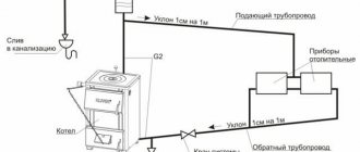
- The slope of the pipes to the last battery in the circuit must be at least 0.5% (preferably 1%);
- The lower line must be laid parallel and symmetrically to the upper one;
- To facilitate operation and repair, radiators, bypass with pump, various technological units must be equipped with taps;
- The supply pipeline requires insulation to avoid loss of coolant temperature during its movement;
- In a system with overhead wiring, the expansion tank is installed in a pre-insulated attic space;
- When laying pipelines, right angles should be avoided, which create additional resistance. Overlaps should also be avoided, as air pockets will form in them;
- Supports for fastening the steel pipeline should be located every 1.2 m;
This is where I will finish the description of two-pipe systems. In the future, I will also consider single-pipe systems with top and bottom wiring; it also has its advantages compared to a two-pipe system, for example, metal consumption, etc. But about all this in new articles.
Most of the heating systems of apartment buildings and private buildings are built precisely according to this scheme. What are its advantages and are there any disadvantages?
Can a two-pipe heating system be installed with your own hands?
Is it possible to convert one system to another?
Theoretically, this is quite possible - both in one direction and in the other. Basically, dependent systems are being modernized, but there may well be a need to reconstruct independent infrastructure. In this case, the most rational option, when it will be possible to preserve the advantages of both systems to varying degrees, will be the implementation of an independent heating system with closed input circuits. This means that those functions that in a standard independent scheme were performed by a separate collector block with a full set of control units, in this case will be taken over by point-mounted devices. At different levels of a home network, before approaching consumers, you can install filters, compressor units, distributors, circulation pumps and a hydraulic tank.
Classification
There are two types of units. The first type is “dry” pumps. In equipment of this type, the coolant and rotor do not interact with each other. The working part of the rotor is isolated and separated from the engine by stainless steel sealing rings. When started, the rings begin to move, a thin film of water seals the connections due to different pressures in the system and in the environment.
The efficiency of a “dry” unit is about 80%. This equipment is very sensitive to water contamination in the system, and if small particles get in, it quickly fails. The dry type pump is quite noisy, so when installing it, care should be taken to soundproof the room.
“Wet” pumps differ in their design from “dry” ones. Its impeller is located directly in the coolant. The stator and the moving part of the mechanism are separated by a special glass that provides waterproofing of the engine. “Wet” units are cheaper to operate and repair, and are quieter than “dry” units.
The disadvantages of “wet” type equipment include their low efficiency - only about 50%. This is due to the low sealing of the sleeve separating the stator and the coolant. Although even this performance is quite enough to heat any private home.
Supply return line
Supply and return pipelines must be tested separately according to the strength of the fixed supports. [1]
Supply and return pipelines for heating, ventilation, and hot water supply systems should be designed separately. [2]
Supply and return pipelines must be laid separately for heating, ventilation, hot water supply and production needs. Fulfillment of this condition allows for the correct calculation of these pipelines and, what is especially important, for easy control over the distribution of circulating fluid among individual systems. [3]
The main supply and return pipelines of the heating supply system, to which hot water boilers, water heating units and network pumps are connected, must be single sectioned or double for boiler houses of the first category, regardless of the amount of heat consumption and for boiler houses of the second category - with a heat consumption of 300 Gcal / h or more. In other cases, these pipelines must be single, non-sectional. [4]
The main supply and return pipelines of the heat supply system, to which hot water boilers, water heating units and network pumps are connected, must be single sectioned or double for boiler houses of the first category, regardless of heat consumption, and for boiler houses of the second category - with a heat consumption of 300 Gcal / h (1 26 TJ) and more. [5]
However, the supply and return pipelines of the network are usually laid with the same diameter, although there are cases when it is advisable to lay pipes of different diameters according to hydraulic calculations. [6]
The laying of supply and return pipelines with a diameter of up to 40 mm may be provided (if necessary) in the thickness of the concrete floor preparation. [7]
The laying of supply and return pipelines in residential, public and auxiliary buildings, as a rule, should be provided in basements, technical undergrounds or under the floor of the first floor (in the absence of basements and undergrounds), as well as above the floor of the lower floor - with technical justification. Distribution and collection lines with a diameter of up to 40 mm can be laid in the thickness of the concrete floor preparation. [8]
The laying of supply and return pipelines in residential, public and auxiliary buildings, as a rule, should be provided in basements, technical undergrounds or under the floor of the first floor (in the absence of basements and undergrounds), as well as above the floor of the lower floor upon technical justification. Distribution and collection lines with a diameter of up to 40 mm can be laid in the thickness of the concrete floor preparation. [9]
The laying of supply and return pipelines in residential, public and auxiliary buildings, as a rule, should be provided in basements, technical undergrounds or under the floor of the first floor (in the absence of basements and undergrounds), as well as above the floor of the lower floor - with technical justification. Distribution and collection lines with a diameter of up to 40 mm can be laid in the thickness of the concrete floor preparation. [10]
The laying of supply and return pipelines of heating systems in residential and public buildings and auxiliary buildings of enterprises should be provided (jointly or separately) in basements, technical floors, attics, underground or, in their absence, under the floor of the first floor (in ducts), and in technical justification also above the floor of the first floor. [eleven]
A differential pressure gauge with an induction sensor of the DMM-K-YuO type is connected to the supply and return pipelines of the local heating system. The pressure drop and water flow in the system are related to each other by a quadratic relationship. Changes in water flow in the system are sensed by a sensor. The signal received from this sensor is proportional to the pressure difference in the system; if the sensor is linear, the signal is directly proportional to the difference and proportional to the square root of the water flow in the system. A signal proportional to the flow rate can be obtained using a functional sensor. [12]