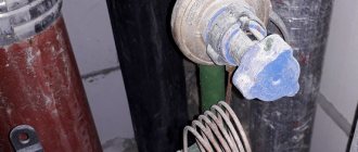
Danfoss ASV-PV, DN15, article number - 003Z5501.
A differential pressure regulator is a special fitting used in piping systems. With this device, the pressure difference of the liquid medium is automatically maintained at the level of preset values. The regulation of differences is carried out by a valve, the flow area of which changes based on pressure parameters.
How are regulators arranged? Design features
Danfoss APT, DN32, article number - 003Z5704.
There are two types of regulators that have fundamental differences:
- The operation of the direct-acting does not require an additional energy source, since the fluctuations are controlled based on the indicators of the water masses. In this case, the valve opens at the moment of a certain discrepancy with the optimal pressure parameters. This process is carried out at a speed corresponding to the speed of parameter changes occurring in the system.
- Indirect-acting regulators can only operate if there is a separately connected power source. The function of measuring elements in such devices is performed by two sensors, through which a signal is transmitted towards the controller. In turn, the control device generates a signal sent to the control valve.
Danfoss ASV-PV, DN20, article number - 003Z5501.
Despite the fact that indirect action products are characterized as high-precision devices, they are rarely used. This is explained, first of all, by the inflated cost and design complexity of such devices.
The automatic direct-acting differential pressure regulator consists of:
- a set point device, which is played by a spring. Some devices are equipped with pneumatic mechanisms or lever-type devices;
- two impulse lines located directly under the valve body itself or built into the pipes;
- meter in the form of a membrane. In some cases, a bellows or piston element is used.
Danfoss ASV-PV, DN15.
Regulator valves are divided into unloaded and unbalanced. In addition, they come in both single and double saddle versions. Moreover, any of these devices can be connected to the pipeline via a threaded or flanged connection, as well as by welding pipes.
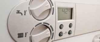
How to set up the regulator yourself?
The operating principle of the devices is the same, but the regulators are different in design.
There are also differences in the design of the adjusting screws. You may need various tools to rotate them.
For more precise adjustments, you can use a pressure gauge. Some devices have special threaded places for their connection.
Preparation
Depending on the design of the adjusting screw, you may need:
- 4 or 6 mm hexagon;
- standard screwdriver with a flat wide blade;
- a special key or a steel strip about 2 mm thick and up to 20 mm wide.
To visually monitor the pressure at the outlet after the reducer, you may need a pressure gauge with an adapter to connect to the shower hose or faucet connector.
The regulator is adjusted at the minimum possible water flow through one water tap.
Settings
To set up the pressure regulator in the apartment’s water supply system, perform the following steps:
- turn off all taps on the internal water supply;
- install a pressure gauge on the gearbox or connect it to the internal water supply;
- open 1 tap so that the water flow is minimal, that is, a thin stream that does not break up into separate drops;
- visually determine the pressure in the water supply using a pressure gauge before starting the adjustment;
- remove the plug from the hole in the housing where the adjusting screw is installed;
- insert the tool into a screw suitable for the configuration;
- to increase the pressure, it is necessary to rotate the screw counterclockwise, the spring load on the valve will decrease, and the valve will close at higher pressure;
- to reduce the pressure, rotate the screw clockwise, the spring load on the valve will increase, and the valve will close at lower pressure;
- make a trial use of tap water to check the comfort of using water;
- if necessary, adjust the setting;
- close the plug of the hole plug on the gearbox, disconnect the pressure gauge.
Some models have a rotation head for the adjusting screw and may even have a scale indicating conventional values.
You can adjust the pressure in the water supply without a pressure gauge. To do this, after each full turn of the adjusting screw, you should check the pressure from the water tap, including the impact of the jet on the palms.
One turn of the screw changes the value by approximately 0.5 - 1.0 bar. For more precise adjustment, at the end of the adjustment, make half a turn of the screw.
This method may turn out to be even more acceptable, because the pressure is adjusted, first of all, for comfortable use of water, including when washing hands.
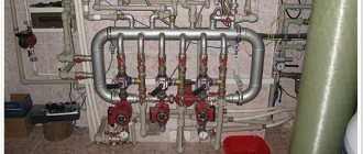
Operating principle of the differential pressure regulator
Currently, membrane-type regulators are predominantly used. Inside such a device there is a chamber with a centrally installed membrane, which is connected to the valve shutter. Due to its displacement to either side, the position of the shutter changes, as a result of which the amount of water masses flowing through the regulator is reduced or increased. The impact on the membrane is carried out through two impulse lines, through which signals are received coming from the supply pipe and the return pipe. The spring, which responds to different pressures, is compressed, thus acting on the membrane, which occupies a certain position.
Danfoss ASV-PV, DN25.
How does a membrane pressure regulator work “after itself”
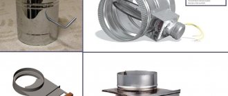
The downstream pressure regulator consists of the following elements:
- Valve inlet and outlet.
- A pipe leading to a chamber with a membrane.
- Chambers with membrane.
- Springs.
- Locking disc.
The principle of operation of such a regulator is that when the water pressure increases and the chamber with the membrane is filled, a rod is activated, which is connected to the locking disk. The membrane presses on it, and the disk blocks the flow of water (fully or partially). When the pressure inside the chamber stabilizes, the locking disc opens the hole. The regulator also operates when the pressure in the system decreases. In this case, the liquid returns to the valve through the pipe from the membrane chamber. By reducing the pressure in the chamber, the locking disk opens and the water pressure increases, increasing its pressure to the optimal value. The main advantage of such a device is its reliability and ease of operation.
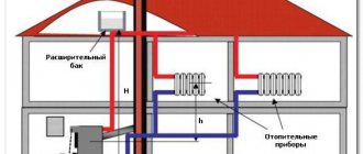
Application area
Modern differential pressure regulators are most often used in water heating systems with hydraulic mode. The presence of such a device allows you to achieve the most stable pressure in the pipes involved in the operation of the heating network. If the device is installed correctly, the heating equipment will be reliably protected from zero flow associated with a system restart.
Danfoss ASV-PV, DN15.
Automatic regulators require virtually no maintenance. With relatively simple manipulations associated with setting up devices, they are able to maintain the specified parameters with fairly high accuracy.
Schemes for changing the air pressure difference
The main way to measure this parameter is to assess the pressure difference between two points (for example, before and after the filter) in the air supply or air conditioning system. To this end, the effect of air moving through the duct must be converted into a corresponding electrical signal. The following types of sensors are used:
- Strain gauge (or resistive).
- Capacitive.
- Inductive.
Strain gauge type device
The principle of operation of a resistive sensor is based on the following. The diaphragm, in contact with the air whose pressure is being measured, deforms as the pressure increases. In this case, the sensors attached to the non-contact surface of the diaphragm are also deformed. The piezoresistive effect, in which the resistance of the strain gauge material changes during deformation, is converted into an electrical signal.
One side of the diaphragm is connected to the low pressure port, and the other side of the diaphragm is connected to the high pressure port. The diaphragm bends and is perceived by the converter as an electrical signal, which is proportional to the difference in the corresponding flow rates.
The differential air pressure sensor is placed in a housing made of stainless steel or other materials with increased corrosion resistance. For ventilation systems, this is due to the need to work with air that has high relative humidity. The resulting electrical signal is passed through a built-in microprocessor, which produces a high-resolution analog signal (from 4 to 20 milliamps) or a digital signal. A design feature of this type of device is the presence of two threaded ports intended for “high” and “low” technological connections. However, the top threaded hole for electrical connection is usually 24 VDC.
Analog and digital output signals are transmitted to the control panel, which is equipped with several dozen (or even hundreds) of connectors, making it possible to computer monitor the current state of air pumping at various points in the ventilation system.
Capacitive device type
A capacitive sensor works like this. The two capacitive contact plates are separated from each other by a small gap. One of them is stationary, and the other, in contact with air, acts like a flexible diaphragm. Increasing air pressure deforms the diaphragm, which narrows the gap and reduces capacity. The change in capacitance is converted into an electrical signal.
Since capacitive-type sensors compare readings of the current air pressure relative to its preset values for some time, they work slower than resistive ones.
Inductive device type
In inductive differential pressure sensors, the deformation of a diaphragm is converted into linear motion of a ferromagnetic core using the principle of inductance. The movement of the core causes a change in the induced current, which is generated by an AC powered coil on another secondary sensing coil. This change, in turn, is converted into an electrical signal. The operation of such a device is clear from the figure.
Inductive sensors respond faster than capacitive sensors, but are structurally more complex and require external additional power.