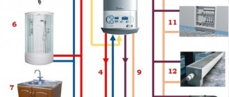
The lack of centralized heating in the private sector requires independent heating of the home. In most cases, the “heart” of the system is the heating boiler. To place it, it is necessary to isolate an area of the house, observing the requirements for safe operation. In addition to boilers, standard equipment is installed in the boiler room: pumps, boilers, collectors, etc. There are many schemes for piping the boiler room of a private house, but in this material we will focus on typical ones and explain how to implement standard solutions in the house.
Boiler room diagram when using solid fuel
An autonomous bunker for a solid fuel boiler does not have strict requirements for footage; the key point is to allocate a separate space, since the heat supply itself is mounted on the floor. It is unlikely that the presence of such a device in the hallway or in the kitchen will satisfy the principles of ergonomics; in addition, it contradicts the principles of safety.
Minimum conditions for operating solid fuel equipment:
- the distance from the wall to the damper is at least 1.2 - 1.5 m; to the sides – 1 m; to the rear – 0.5 m; to the cut of the tee for the rear type of connection – 50 cm;
- making room surfaces from fireproof material or plastering them, lining them with mineralite;
- supply of fresh ventilation, which can be represented by a gap between the door and the floor or a hole in the wall;
- exclusion of superstructures above the bunker.
Technological composition of a boiler room with a TT heat generator
The list of equipment for heating with solid fuel includes:
- boiler with the necessary tanks, reservoirs, etc.;
- complete safety group, three-way mixing valve, circulation pump in the piping structure of the heating device;
- a boiler heated by a TT boiler, providing housing with hot water;
- smoke exhaust pipe of effective diameter and height;
- an organized drainage complex in case of device downtime;
- weather-compensated or customizable automation;
- fire removal and fire extinguishing system.
Solid fuels include firewood, coal, and peat. For their location it is also necessary to isolate a certain area.
Schematic diagram for a closed boiler room
Due to the load on hot water supply, devices with a total heat consumption of up to 50 m² per 1 Gcal/h are used for large rooms. This type of installation is called a closed type boiler room.
It consists of 11 elements:
- Hot water boiler.
- Recirculation pump.
- Network piston.
- Line of the same name.
- Raw liquid pump.
- Condensate.
- The same tank.
- Raw water heater.
- Deaerator.
- Chemically purified water supply.
- Evapor cooler.
Workflow Description
To control natural gas consumption, it is necessary to determine the amount of network water leakage.
This amount is equal to 2% of all liquid entering the line.
A closed thermal system works according to the following principle. The water inside the device heats up. With the help of pumps, it moves through pipes and enters the battery. There her temperature drops. After which the liquid is returned through the return line to the heating boiler. Here the water temperature rises again, and a new circle of movement begins.
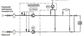
A water heating boiler is located in a house or apartment, and to the left of it is a deaerator. Below them are pumps and a heat exchanger. Water flows through the network line from the tank to the batteries. For this purpose, a pump and a main pipeline are used. This fluid line directs hot water from the boiler to the radiator.
Boiler room plan with gas boiler
Using natural gas as a coolant is an economical and productive solution, but carries a high risk due to the risk of explosion. For this reason, the arrangement of a room for a gas boiler has strict requirements set out in SNiP.
This type of fuel, even in small quantities, can have harmful effects on health, so one of the important principles for the safe use of gas is good ventilation. The lack of high-quality hood entails less heat transfer at the same consumption.
The layout of the boiler room equipment of a private house depends on its power and the operating state of the gas. The liquefied form categorically does not allow the installation of a heat supply source in the basement. The specific gravity of such a carrier is much greater than air; in case of leaks, it is concentrated in the lower reaches of the building, where it can initiate an explosion.
There is no need to look for or build a separate corner for devices with a power rating of up to 60 kW. Installation in the kitchen, attic, pantry, etc. is quite possible if they meet the following conditions:
- the presence of a window with a window;
- volume of at least 15 cubic meters and on top 0.2 cubic meters for each allocated kilowatt;
- height minimum 2.5 m.
More powerful units should be placed in separate cabins on any floor, while the basement should be considered last. Free-standing boiler rooms must have their own foundation with a certain proportion of sand in it. The point where the apparatus is heated must be brought into compliance with the standards:
- windows from 0.5 sq.m.,
- doorway width from 0.8m,
- sheathing with fireproof material with a fire resistance limit of at least 45 minutes,
- availability of free space around the heat generator with a radius of 0.7 m or more.
Set of technical equipment for a gas boiler room
The use of gas for heating is carried out with the participation of:
- heating boiler;
- a boiler, heated by gas equipment, providing housing with hot water;
- a distribution manifold, which includes a circulation pump, a hydraulic distributor and a comb;
- an expansion tank that serves as a neutralizer for increasing pressure due to an increase in the temperature of the medium;
- safety groups complete with pressure gauge, safety valve and air vent;
- a smoke exhaust pipe with an effective diameter and a height above the roof ridge of at least 5 m with an additional channel for cleaning;
- an organized drainage complex in case of device downtime;
- navigation in the form of electronic automation;
- fire removal and fire extinguishing system.
Thermal diagrams of boiler houses with hot water boilers for open heat supply systems
Thermal diagrams of boiler houses with hot water boilers for open heat supply systems
In open heat supply systems, the water prepared in the boiler room not only serves as a coolant, but also goes to the needs of hot water supply. Water is collected directly from the pipelines of the heating network without intermediate heaters. Thermal schemes of boiler houses with hot water boilers for open heat supply systems differ from those for closed ones, mainly in terms of water treatment capacity for feeding heating networks. The amount of make-up water in this case is determined by water losses in networks, in the boiler room and water consumption for hot water supply needs. To give an idea of the amount of water for closed and open heating systems, below are the costs based on typical boiler house projects. For example, the estimated maximum hourly water consumption for replenishing heating networks in boiler houses with a heating capacity of 150 Gcal/h for a closed heating system is 45 m3/h, for an open one - 670 m3/h.
Rice. 5.11. Principal thermal diagrams of boiler houses with hot water boilers for open heat supply systems.
Option of the circuit without installing a tank and deaerated water pumps. 1 - hot water boiler; 2 — network pump; 3 - circulation pump; 4 — summer network pump; 5 - recirculation pump; 6 — make-up pump; 7 - raw water pump; 8 - pump for supplying water to the ejector; 9 - deaerator; 10 - vapor cooler; 11 — ejector; 12 — working water tank; 13 - tank - battery; 14 — raw water heater; 15 — heater of chemically purified water.
Since water consumption in an open system is uneven over time, in order to level the daily schedule of loads on hot water supply and reduce the design productivity of water treatment equipment, it is necessary to install accumulator tanks for deaerated network water. Of these, during peak consumption hours, hot water is supplied to the network pumps by make-up pumps. In addition, in order to avoid cooling of water in the networks during the hours of minimum consumption in the summer, it is necessary to pump about 10% of the maximum flow, which is associated with an increase in electricity consumption.
The quality of water preparation for replenishing an open heating system must be significantly higher than the quality of water for recharging a closed system, since the same requirements are imposed on water for hot water supply as for drinking tap water. The emergence of large storage tanks for deaerated water complicates the thermal circuits of hot water boiler houses. Since the charging and discharging of these tanks can be carried out in various ways, several variants of thermal circuits have been developed to include deaerators and accumulator tanks.
In Fig. 5.11 shows the basic thermal diagrams of boiler houses with hot water boilers for open heat supply systems.
System with hot water boilers 1, the elements of which do not differ from those shown in Fig. 5.7, with the exception of the battery tank 13 and the system that creates a vacuum in the deaerator, consists of a water-jet ejector 11, a tank of “working” water 12 and a pump 8 supplying water to the ejector. From the deaerator 9, water flows by gravity into the accumulator tanks 13, and from there it is pumped out by make-up pumps 6 and supplied to the suction manifold of network pumps 2. This scheme for switching on equipment for low-capacity boiler houses, less than 20 Gcal/h, turned out to be not reliable enough in operation, since it is difficult to maintain a given water level in the deaerator 9 and tanks 13, without which normal operation of the deaerators is impossible.
The difficulty of maintaining a constant level in the deaerator is explained by fluctuations in the level in the tank - accumulator 13 and different hydraulic resistance of the pipelines. Another variant of the thermal scheme is also possible, in which water from the deaerator tanks flows by gravity into the deaerated water tank, then to transfer pumps that supply water to the accumulator tanks. Water is taken from the storage tanks by make-up pumps and supplied to the heating networks. This scheme ensures reliable operation of deaerators, but requires the installation of two groups of pumps - pumping and make-up, which increases the cost of the boiler installation.
Giprokommunenergo [26] has developed other Thermal diagrams of boiler houses with hot water boilers for open heat supply systems. Thermal diagrams of boiler houses with hot water boilers for open heat supply systems, shown in Fig. 5.12, include a group of three make-up pumps 6, which is used simultaneously both for replenishing heating networks and for charging tanks - accumulators 13 of make-up water. At night, when the withdrawal of water from the networks is insignificant, the make-up pump 6 drops water from the deaerator tanks into the accumulator tanks 13 and to feed the heating networks, where a small part of this water goes. With an increase in water withdrawal from the networks, the second make-up pump 6 comes into operation, which takes water from the accumulator tanks and supplies it to the suction line of the network pumps 2; the third make-up pump in this scheme is a backup one.
Thermal diagrams of boiler houses with hot water boilers for open heating systems also have disadvantages, mainly related to the productivity and pressure of make-up pumps. When pumping water from the deaerator tank to the accumulator tank, an almost constant pump 6 performance and a relatively low pressure, lying in the range of 15 - 20 m of water, are required. Art. In heating networks with an open hot water supply system, the flow rate of make-up water varies significantly during the day, the pressure varies from 30 to 60 m of water. Art., as a result, the power and energy consumption of the pumps are different.
Rice. 5.12. Schematic thermal diagram of a boiler room with hot water boilers for an open heat supply system.
Variant of the scheme without installing deaerated water pumps. Explication of equipment - see fig. 5.11.
When choosing this or another scheme for turning on pumps to feed heating networks, it is necessary to compare the technical and economic indicators of several schemes, which should take into account the energy costs for driving pumps under different operating modes.
Shown in Fig. 5.11 and 5.12, schematic thermal diagrams of boiler installations for open heat supply systems show that the general order of switching on equipment and organizing coolant flows changes slightly compared to the considered diagrams of closed heat supply systems.
The water in the chemically purified water heater is heated from 20 - 30 ° C to 55 - 70 ° C and fed into the column of the vacuum deaerator. The vacuum (about 0.3 kgf/cm2) in the installation is maintained by suction of the steam-air mixture from the column using water-jet ejectors or liquid ring pumps of the RMK type. Water for the ejectors circulates in a closed loop: “working” water tank 12, pump 8, ejector 11 back to the tank together with the condensate of the steam-air mixture from the make-up water deaerator. The pressure of water ejecting the mixture is maintained within 40 - 50 m of water. Art.
The steam-air mixture is also cooled in front of the ejectors in vapor cooler 10. The deaerated water tank, as a rule, should be located at the zero mark of the boiler room, and the vacuum deaerator column should be installed at a level that ensures the pressure in the deaerated water tank is equal to atmospheric pressure. In practice, the deaerator column is usually installed at a height of 7.5 - 8.0 m from the boiler room floor.
Water from the return line of heating networks with a temperature ranging from 35°C to 70°C is supplied together with make-up water to the suction manifold of network pumps 2, the latter is pumped into hot water boilers 1 or through the bypass line and the flow regulator goes into the supply line of the heating networks.
An expanded thermal diagram of a boiler room with three hot water boilers KV - GM - 10 for an open heat supply system is shown in Fig. 5.13. The main directions of coolant flows are discussed above when describing the basic thermal diagram. The choice of equipment for deaeration and water pumping is the main task when developing such extensive thermal circuits of boiler houses. For open hot water supply systems, the second most important element of the thermal circuit, after the hot water boiler, is a deaeration installation with storage tanks. Due to high water consumption, a vacuum deaeration method is usually used.
The performance of the deaeration installation is selected so as to ensure reliable removal of gases from the make-up water, both in winter and in summer periods of operation of the installation.
The total capacity of tanks - accumulators for make-up water is assumed to be 6 - 8 times greater than the average hourly water consumption per day for domestic hot water supply. The accepted capacity of the accumulator tanks should ensure that heating networks are fed with water during the hours of maximum water withdrawal. Usually, at least two metal tanks are installed, the inner surface of which is protected with an anti-corrosion coating, and the outer surface with thermal insulation. The number, unit capacity and developed pressures of pumps must comply with the requirements for regulating the operation of heating networks while economically using electricity to drive them. Such conditions sometimes dictate the need to use an increased number of pumps in the thermal circuits of boiler houses - network (winter and summer), pumping, recirculation and make-up (also winter and summer).
In the summer, when there are no thermal loads on heating and ventilation, water consumption decreases and at the same time the temperature and pressure of the supplied water decreases.
Rice. 5.13. Detailed thermal diagram of a boiler house with three hot water boilers KV - GM - 10.
1 — hot water boiler; 2 - raw water pump; 3 — network pump; 4 - summer mains pump; 5 - recirculation pump; 6 — make-up pump; 7 — summer make-up pump; 8 - circulation pump; 9 - deaerated water pump; 10 - working water pump; 11 - tank - battery; 12 — raw water heater; 13 — heater of chemically purified water; 14 — tank of deaerated water; 15 - deaerator; 16 — vapor cooler; 17- ejector; 18 — working water tank.
To ensure reliable operation of hot water boilers and the piping system in the boiler room in the design temperature conditions (i.e., a constant water temperature at the boiler outlet of 150 ° C, especially when operating on high-sulfur fuel), it is necessary to maintain a minimum pressure in the system of at least 80 m of water . Art.
In isolated cases, it is proposed to use the so-called dual-circuit coolant flow system.
In the figure shown. 5.13 of the detailed thermal diagram of the boiler room when operating in summer mode, the water heated in the boilers circulates along the internal circuit: boilers 1 - chemically purified water heater 13 - raw water heater 12 - circulation pumps 8 - hot water boilers 1. With this switching on, only a small amount of hot water is needed feed into the column of a vacuum deaerator.
The second circuit of the circulating network water in the diagram can be represented as follows: water from the water supply goes to the raw water pump 2, to the raw water heater 12, then to the water treatment plant, then to the chemically purified water heater 13 and to the column of the vacuum deaerator 15. From here the water it flows by gravity into the deaerated water tank 14 and then to the transfer pump 9, which supplies water at a temperature of 70°C to the accumulator tanks 11.
Summer network pumps 4 from storage tanks 11 pump water into the supply line of the heating networks and to the hot water consumer. Only a small part of the water from the secondary circuit is used to recharge the internal primary circuit. Water from heating networks, in the absence of heat consumption for heating and ventilation, is sent to storage tanks. Water consumption in such cases is conventionally assumed to be 10% of water consumption for hot water supply.
The transfer of the boiler room from the devil to the heating mode of operation is carried out by appropriate changes in the direction of coolant flows using shut-off valves installed on the pipelines. The main advantages of open heat supply systems include reduction in the cost of water treatment of hot water supply due to its centralization in boiler houses instead of many heating points in the area, reduction in the cost of heating networks due to a decrease in the amount of water circulating in them, reduction in the cost of subscriber inputs due to the lack of water heaters and circulation systems there. pumps
At the same time, a number of disadvantages of open heat supply systems should be noted: increased requirements for the quality of network water, which must correspond to the quality of drinking water; When there is a sudden change in water flow, hydraulic shocks are sometimes observed, especially when water is supplied only for hot water supply.
When choosing a heating system, you need to take into account at least three features of the source water used for make-up: the tendency to low-temperature scale formation; corrosiveness; prone to sulfide contamination.
It is recommended to select heat supply systems in two stages:
- preliminary selection based on the classification of source waters;
- the final choice is based on water analysis carried out over a period of at least one year, taking into account probable future changes in the parameters of source waters [44].
Based on the results of the analysis of technical and economic indicators regarding the reliability, advantages and disadvantages of both systems in operation, as well as based on the real possibility of obtaining high-quality water to recharge heating networks and comparing the specific capital investments for the construction of the entire heat supply complex, a boiler house and heating networks can be made choice of open or closed heating system.
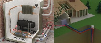
Boiler in the boiler room diagram
To provide a private home with hot water near the heat supply source, an indirect heating tank - a boiler - is used in the boiler room circuit of a private home. The main functional element is a coil made of steel or brass placed inside the container and having an impressive surface area. Heating such a heat exchanger is the task of hot water (or other coolant). To avoid rapid cooling of the tank, the body is lined with thermal insulation. The element in modern models is equipped with a magnesium anode, which prevents the development of corrosion processes and increases the service life of the part. A fuse, temperature sensor and pressure gauge as part of the safety group protect the device from high pressure.
Operating principle:
- the tank is filled with cold water;
- hot media flows from the boiler into the heat exchanger;
- the heated surface of the coil gives off heat to the water mass;
- Warm liquid comes out of the outlet.
The navigation panel built into the latest generation modifications allows you to regulate the flow to the heat exchanger, thanks to a temperature sensor. In terms of dimensions, the equipment has a significant range - from 80-100 liters to 1400-1500 liters. The model range also includes those that, along with the ability to heat up using a boiler, can be powered by electricity and other energy sources.
Installation requires compliance with some rules:
- location as close as possible to the heat generator (boiler);
- organization of a flat, non-slip surface;
- equipped with a hydraulic accumulator to prevent thermal expansion;
- installation on all circuits of ball valves for comfortable and safe operation;
- equipping with check valves to prevent backflow;
- insertion of filters to improve liquid quality;
- correct position of one or more pump units when the motor axis is placed horizontally.
Scheme with hydraulic arrow
The water arrow in the boiler room circuits of the house prevents the occurrence of thermal shock. The essence of its action is to separate and link several circuits.
Carrying out one-time operation of heating, hot water supply, heated floors involves an unstable load and variability of the thermo-hydraulic properties (temperature, pressure drops) of the networks. The heat supply source does not tolerate instability well, so a hydraulic arrow is installed between it and the consumer branches.
The main function of the device is to set the coolant in the desired direction automatically in order to avoid thermal shock.
All work on the design and installation of a boiler room for the UniMall shopping complex
- Design
- General data on the boiler room
- Thermomechanical boiler room solutions
- Heating and ventilation systems
- Boiler room water supply systems
- Boiler room sewage system
- Internal fire extinguishing system
- Fuel supply to the boiler room
- Architectural and construction part
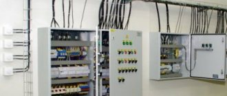
- Boiler room electrical equipment
- Boiler room electric lighting
- Lightning and electric shock protection
- Boiler room automation system
- Automation of auxiliary equipment
- Boiler room security and fire alarm system
The value of a heat accumulator in a boiler room
Thermal accumulators, otherwise called buffer tanks, are most effective in boiler rooms of private houses with solid fuel boilers. Their use allows you to create contours with natural circulation. These are the paths along which the coolant moves during a power outage, and, as a result, the pump stops working.
The operating principle of a heat generator with a heat accumulator is as follows:
- simultaneously with the supply of heat to the heating system, the heat supply heats the medium in the buffer tank;
- after turning off the TT boiler, the temperature sensor signals the pump, which initiates the supply of the media accumulated in the heat accumulator tank to the network;
- When the required temperature is reached, the sensor sends a signal to turn off and the heat supply stops.
Cooling of the coolant occurs slowly, thanks to good thermal insulation. Cycles of starting and stopping the pump occur many times until the water in the heat accumulator cools down.
When tying with heating equipment, a large number of turns and bends should be avoided. The diameter of the pipes must correspond to the boiler pipes.
Buffer capacity value:
- improved safety;
- economic benefit;
- creating more comfortable conditions.
General design provisions
Each step of installing a boiler installation must be thought out, so you should not try to design communications and install equipment yourself; it is better to contact specialists who have extensive experience in installing engineering systems for private cottages. They will give a number of valuable tips, for example, help you choose the most optimal boiler model and determine the location of its installation.
Let’s assume that for a small country house, a wall-mounted unit is sufficient, which can easily be located in the kitchen. A two-story cottage, accordingly, needs a specially designated room, which must be equipped with ventilation, a chimney, a separate exit and a window. There should be enough space to accommodate the remaining components: pumps, boiler, connecting elements, pipes, etc.
The process of designing a boiler room for a private house includes several points:
- preparing a diagram of the boiler room regarding its location inside the house;
- equipment distribution diagram indicating the main technical characteristics;
- specification for materials and equipment used.
In addition to purchasing system components and their installation, as well as graphic work, which should include a schematic diagram, professionals will help with the preparation of the necessary documents.
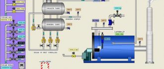
An example of a schematic diagram of a hot water boiler house: I – boiler; II – water evaporator; III – source water heater; IV – heat engine; V – capacitor; VI – heater (additional); VII – battery tank