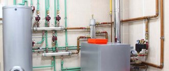
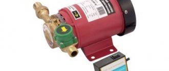
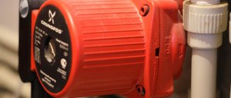
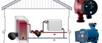
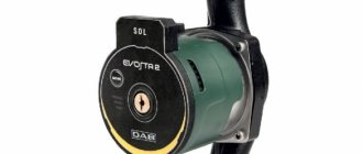
To increase the efficiency of heating and hot water supply systems, they are equipped with a recirculation pump, the task of which is not only to increase the pressure of the medium transported through them, but also to ensure its circulation in a continuous mode. In some cases (in particular, when installing autonomous hot water supply and heating systems), only a recirculation pump can cope with this task.
Circulation pump in a hot water supply system
Before equipping a hot water supply or heating system with a recirculation pump, you should understand how this equipment works. It is also advisable to study the principle of operation of the circulation pump.
Purpose and scope
Hot water recirculation pumps have a very important function. With the help of such devices, closed pipelines through which hot water is transported operate in the required mode. By pumping liquid into the pipeline due to the rotation of special elements, recirculation electric pumps increase the pressure of the liquid medium they pump and, accordingly, the speed of its movement.
Most often, heating systems are equipped with recirculation pumps, which increases not only the efficiency, but also the cost-effectiveness of the latter. Most of these systems, as is known, operate using a coolant, which, moving through a pipeline, releases heat into the room. Heating of the coolant (in this case, before it is supplied to the pipeline) is provided by a boiler, boiler or water heater. After passing through the entire heating circuit, the water must return to the heating equipment, where it is again given the required temperature.
DHW recirculation scheme
Without the use of special pumping equipment, water circulation in the heating system will flow slowly, and in some cases may not flow at all, since the pressure of the coolant flow, which is not further increased in any way, will be dampened by the pipeline elements. The result of this is unevenly heated heating pipes and, accordingly, an uncomfortable temperature in the premises of the house.
A circulation pump for hot water supply increases the pressure and pressure of hot liquid moving through a closed pipeline circuit. The use of circulation pumps for hot water is especially important in the pipeline systems of houses with an area of more than 200 m2, in which there are several water intake points, and the boiler is installed in a separate room or in the basement. Water in such pipelines (as a rule, quite long), if they do not have a recirculation system using a special pump, cools down quite quickly. This leads to the fact that when you open the tap you have to wait a long time until liquid heated to the required temperature flows out of it.
In addition, when some taps at water intake points are opened immediately, the water pressure in them drops, because the pressure of the liquid moving through the pipeline by gravity is not additionally supported by anything. To solve precisely these problems faced by owners of private and apartment buildings, a hot water pump is designed to provide forced movement, as well as the creation of stable water pressure and pressure in the hot water supply system.
The recirculation pump should not be installed near tanks or water heaters, the heat from which could affect the thermostat.
Using a circulation pump for heating and hot water supply to a private home, in addition to the above advantages, allows you to save on energy costs. Since in systems with recirculation, water from the boiler is transported through pipes forcibly and reaches all water intake points and heating radiators much faster, its temperature during such transportation decreases slightly. A boiler, if forced water recirculation is provided in the pipeline it serves, requires less time to heat it, and accordingly, the consumption of energy carriers used to operate the heating equipment is reduced.
Pumps for circulating hot water are actively used to equip “warm floor” systems, the design of which assumes the presence of an extended pipeline circuit of a complex configuration, consisting of small-diameter pipes. In such cases, the circulation pump ensures constant movement of the coolant through the pipes.
The circulation pump is a mandatory element of the underfloor heating system
Functions of recirculation pumps
Increasingly, boilers are used to heat water in private houses and apartments. As a rule, they are installed in the basement or other technical room of the building. Due to the fact that bathrooms and taps are located in different parts of the residential building, residents need to wait until the heated water reaches a certain point in the building. This often takes several minutes, as a result of which a certain part of the water ends up in the sewer. The longer the pipeline, the more fluid is lost by the system.
To avoid loss of water and heat, many residents install recirculation pumps. They are designed to maintain a stable temperature in front of all water intake points in the house. In addition to the pump for recirculating hot water, a drain line is installed into the system, through which the coolant returns to the water heater. However, not all modern water heaters are equipped with a connection for connecting the drain line. In this case, the outlet line must be connected to the cold water supply line.
Another function of the recirculation pump is to increase the temperature of the coolant in most of the home's plumbing system.
Thus, answering the question: “What is water recycling?”, we can say that it is the acceleration of the movement of water through pipes and its forced return to the coolant without loss of temperature and properties of the liquid.
Design Features
For DHW circulation, centrifugal pumps with a “wet” rotor are mainly used. The operating principle of such a circulation pump is quite simple.
- Water entering the chamber of the recirculation pump through the inlet pipe is captured by the blades of the impeller, which is rotated by the drive motor shaft.
- Centrifugal force begins to act on the water, which throws it towards the walls of the working chamber, where increased pressure is created.
- Under the influence of pressure generated by centrifugal force, the liquid is pushed into the pressure line of the recirculation pump.
- The suction of the next portion of hot water into the working chamber occurs due to the fact that air rarefaction is created in the central part of such a chamber during the processes described above.
Design of a centrifugal circulation pump with a “wet” rotor
It should be borne in mind that a conventional centrifugal water pump is not suitable for heating and hot water supply, since the operating conditions of such equipment do not provide for a high temperature of the pumped liquid. For the manufacture of pumps that recirculate hot water, materials are used that are resistant to increased loads and high temperatures. In addition, such electric pumps, which operate primarily indoors, must be low-noise so as not to make living conditions in a private or apartment building uncomfortable. No less important characteristics of electric pumps for DHW circulation are compactness and efficiency in terms of electricity consumption.
When selecting pumping equipment that will need to work with hot water, you should also keep in mind that pumps for DHW recirculation differ in operating conditions from devices used to equip a heating system. Thus, pump models for a boiler room are designed to pump water whose temperature reaches 90°, while devices that circulate hot water can work with a liquid medium heated to 65°. As such, they are not interchangeable, although if necessary, an electric heating pump can be used to circulate hot water in DHW systems. However, replacing such devices cannot be done in the reverse order.
Domestic pumps are designed to recirculate water in small hot water systems
Main characteristics
When choosing a circulation pump for domestic hot water or heating, you should pay attention to the following characteristics:
- productivity – the amount of liquid that a recirculation electric pump is capable of pumping per unit of time (m3/hour or liter/min);
- pressure or pressure of the liquid medium created by the pump (meters of water column or Pa);
- power consumed by the recirculation pump (W);
- method of controlling the device (using a timer or temperature sensor).
Since recirculation pumps pump small volumes of liquid, which moves in heating pipes or water pipes at low speed, such devices do not require high power and performance. Thus, to maintain the water temperature in domestic heating and water consumption systems, the length of which does not exceed 40–50 meters, a recirculation pump with a capacity of 0.2–0.6 m3/hour will be quite sufficient.
Grundfos pump with a capacity of 3.3 cubic meters. m/hour
In terms of electricity consumption, boiler and hot water pumps are also economical, since their power, depending on the model, ranges from 5 to 20 W. This is quite enough for the electric water pump to be able to ensure efficient circulation through the hot water pipes in a private house.
It is very important to choose the right circulation pump according to such a parameter as the pressure of the liquid flow that it is capable of creating.
To choose the right pump according to this characteristic, you can follow the following recommendations when selecting recirculation equipment for heating and hot water systems of both a small residential building and a large cottage with several floors.
- If the pipes through which the pump must circulate the liquid medium are located at the same level, then we select equipment with a pressure value of 0.5–0.8 meters of water column.
- If the house has several floors, DHW recirculation must be ensured at several levels of the pipeline, which means that the height to which the liquid must be raised must be taken into account.
In order to make recirculation of the liquid medium more efficient in heating and hot water systems, pumps should be selected with a certain reserve in the pressure generated.
Recirculation pumps for hot water boilers
⇐ PreviousPage 8 of 9Next ⇒
Recirculation pumps of hot water boilers are installed to increase the water temperature at the inlet to the boiler unit in order to protect the convective heating surfaces of hot water boilers from corrosion.
The performance of recirculation pumps is determined in the calculation of the thermal circuit.
In practice, the resistance of the recirculation circuit, including the hot water boiler, lies in the range of 20 to 30 mV. Art. The number and supply of recirculation pumps depend on the thermal circuit for switching on the equipment (general station or aggregate). The most commonly used recirculation pumps are NKU type pumps from the Katai Pumping Plant, which are designed to pump water with temperatures up to 200 °C at a pressure of 20 to 40 m of water. Art. with a supply from 75 to 250 m3/hour.
Water consumption for recirculation for maximum winter mode Grec = 180.9 t/h.
Volumetric water flow for recirculation for maximum winter mode:
where ρmax.z – coolant density at temperature for maximum winter mode, ρmax.z=0.917 t/m3 for τ1=150ºС;
According to water consumption Vrec = 197.3 m3/h and pressure Hrec = 30 m w.st. choose the NKu-140 pump, pump flow in the range of 115-200 m3/h, pressure 25-40 m w.c.
Raw water pumps
To supply water from the water supply source of the boiler house - water reservoir, water supply of an industrial or residential area - raw water pumps are installed in the water treatment system of the boiler house. The supply of these pumps is determined by the maximum demand for chemically purified water and its consumption for the own needs of chemical water treatment. Water consumption for the own needs of chemical water treatment is determined when calculating the thermal diagram of the boiler house.
In addition to the consumption of raw water for chemical water treatment, there are other costs of the boiler room that should be taken into account when determining the supply of raw water pumps. For example, chemically purified water is used to cool the bearings of pumps and sensors of control and measuring instruments; water after washing chemical water treatment filters, condensate from the fuel oil industry, water from showers and washbasins, and other water contaminated in production are used for the hydroash removal system.
The required pressure of raw water pumps is selected depending on the hydraulic resistance of pipelines, fittings, filters and hydrostatic pressure of water and usually ranges from 40 to 60 m w.c.
If the source water pressure is approximately 40-60 m of water. Art., then it is enough to overcome the hydraulic resistance of pipelines and boiler room equipment, which makes it possible not to install raw water pumps.
Based on the calculation of the thermal scheme, the consumption of raw water supplied to chemical water treatment for the maximum winter mode is Gs.w. = 99.0 t/h;
Volumetric flow rate of raw water for maximum winter mode:
where ρс.в – density of raw water, ρс.в=1.0 t/m3 at cold water temperature tх.в.=5 оС. The temperature of cold water in the water supply network, during the heating period with unknown data, is recommended to be equal to 5 ºС, in the non-heating period 15 ºС [13].
Based on water flow Vs.w.=99.0 m3/h and pressure Hs.w=50 m w.st., we select two Grundfos NKG 125-80-400 pumps, one of which is a backup (see Figure 2.16 Figure) with rotation speed nus = 1480 rpm [11].
Bibliography
1. Subbotin, V. I. Heat supply sources and their operating modes: textbook; 2nd edition, supplemented by the State Educational Institution of Higher Professional Education "ISUE named after V.I. Lenin". – Ivanovo, 2010. -400 s
2. Esterkin, R. I. Boiler installations. – L.: Energoatomizdat. 1989. – 280 p.
3. Gavra, T. G., Mikhailov P. M., Ris V. V.. Thermal and hydraulic calculation of heat exchangers. – M.: 2001. – 58 p.
4. Sokolov, E. Ya. Heating and heating networks: a textbook for universities / E. Ya. Sokolov 7th edition - M.: MPEI publishing house, 2001. - 472 p.
5. SP 124.13330.2012. Heating network. M.: 2012, - 59 p.
6. SP 131.13330.2012. Construction climatology. – M.: 2012.-
7. SP 60.13330.2012. Heating, ventilation and air conditioning. – M.: 2012. -64 p.
8. Water heating networks: A reference guide for design / edited by N.K. Gromov, E.P. Shubina - M.: Energoatom publishing house, 1988, - 376 p.
9. Subbotin V. I., Kalinin N. V. Pumps in heat power engineering / State Educational Institution of Higher Professional Education “Institute of State Power Engineering named after V. I. Lenin”. – Ivanovo, 2007. – 148 p.
10. SP 89.13330.2012. Boiler installations.
11. GOST 16860-88 “Thermal deaerators”
12. Catalog GRUNDFOS. Industrial cantilever and monoblock pumps according to ISO 2858 50 Hz. -400 s.
13. Industry catalog 44-97. New heat exchange equipment for industrial power plants and heat supply systems. M.: Central Research Institute Tyazhmash. 1998. – 95 p.
14. GOST 30494-2011. Residential and public buildings. Indoor microclimate parameters.
15. Manual for SNiP 01/23/99. Construction climatology.
16. SP 41-101-95. Design of heating points.
17. GOST 27590-88. Water-water heaters for heating systems.
APPLICATIONS
Appendix 1. Options for assignments for course work
| Designation | Value for maximum winter operating mode of the boiler room (according to options) | ||||||||||
| Boiler room location | — | Yaroslavl | Vladimir | Ivanovo | Krasnoyarsk | Volgograd | Moscow | Perm | Irkutsk | Minsk | Kaliningrad |
| Maximum heat consumption (taking into account losses and consumption for fuel oil facilities), MW: - for heating residential and public buildings; — for ventilation of public buildings; - for hot water supply. | Qo Qв |
Appendix 2. Technical characteristics of boiler units of the KVGM brand
| Specifications | KV-GM-7.56-150H | KV-GM-7.56-115H |
| Nominal heating capacity, MW | 7,56 | |
| Type of fuel: | gas/liquid fuel | |
| Working water pressure, (at the boiler outlet), MPa | 1,0 | 0,43 |
| Inlet water temperature, °C | ||
| Outlet water temperature, °C | ||
| Design hydraulic resistance, MPa, no more | 0,25 | 0,25 |
| Heat output control range, % | 30…100 | |
| Water consumption, t/h | 80,5 | |
| Fuel consumption, - on gas, m3/h - on light liquid fuel, kg/h | 802 692 | 798 692 |
| Exhaust gas temperature, °C - on gas - on light liquid fuel> | 130 155 | 118 151 |
| Boiler efficiency, %, - on gas - on light liquid fuel | 94,0 92,7 | 94,5 92,8 |
| Design aerodynamic drag, Pa - on gas m3/h - on light liquid fuel, kg/h | 86,0 87,2 | 81,0 98,0 |
| Gas pressure, no more than, Pa | ||
| Combustion chamber volume, m3 | 16,9 | |
| Furnace wall surface, m2 | 43,2 | |
| Heating surface of the convective part, m2 | ||
| Water volume, m3 | 3,27 | |
| Air consumption, Nm3/h - on gas - on light liquid fuel | 8070 8130 | 8030 8130 |
| Gas consumption, Nm3/h - on gas - on light liquid fuel | 9032 8739 | 8937 8757 |
| Estimated (excess) water pressure at the boiler inlet, MPa | 1,6 | 1,6 |
| Boiler service life, not less than years |
Continuation of Appendix 2
| Specifications | KV-GM-11.63- -150 | KV-GM-23.26- -150 | KV-GM-35-150 |
| Nominal heating capacity, MW | 11,63 | 23,26 | |
| Type of fuel: | gas/fuel oil* | ||
| Estimated (excess) water pressure at the boiler inlet, MPa | 2,5 | ||
| Minimum (absolute) water pressure at the boiler outlet, MPa | 1,0 | ||
| Inlet water temperature, °C | |||
| Outlet water temperature, °C | |||
| Hydraulic resistance, MPa | 0,25 | ||
| Heat output control range relative to nominal, % | 20-100 | ||
| Boiler design weight, kg. | |||
| Weight of boiler metal, kg (GMO/shot cleaning). | 19000/18400 | 26000/25100 | 33200/32400 |
| Water consumption, t/h. | 123,5 | ||
| Fuel consumption, m³/h-gas/kg/h-fuel oil | 1220/1220 | 2580/2450 | 3870/3680 |
| Mean time between failures, no less | |||
| Full designated service life of the boiler, years, no more | 20 years or 100,000 hours | ||
| Boiler efficiency, %, not less, gas/fuel oil | 92,5/89,0 | 92,3/91,0 | 91,8/90,4 |
| Specific NOx emission at α=1.4, kg/GJ, no more, gas/fuel oil | 0,02/0,05 | 0,02/0,05 | 0,02/0,05 |
| Specific CO emissions, mg/m³, no more, gas/fuel oil | |||
| Equivalent noise level in the service area, dBa, no more | |||
| Temperature of the external (insulated) heating surface of the boiler, no more than, °C | |||
| Total aerodynamic resistance, mm.water.st., gas/fuel oil | 44/46 | 57/60 | 65/67 |
| Flue gas temperature, °C, gas/fuel oil | 185/230 | 190/242 | 185/250 |
Continuation of Appendix 2
| Specifications | KV-GM-58.2-150 | KV-GM-116.3-150 | KV-GM-139.6-150 |
| Nominal heating capacity, MW | 58,2 | 116,3 | 139,6 |
| Type of fuel | gas/fuel oil* | ||
| Estimated (excess) water pressure at the boiler inlet, MPa | 2,5 | ||
| Minimum (absolute) water pressure at the boiler outlet, MPa | 1,0 | ||
| Inlet water temperature, °C, main mode | |||
| Inlet water temperature, °C, peak mode | — | ||
| Outlet water temperature, ° C | |||
| Hydraulic resistance, MPa, no more | 0,25 | 0,35 | 0,35 |
| Heat output control range relative to nominal, % | 20-100 | ||
| Boiler design weight, kg. | 115 800 | 135 000 | 183 200 |
| Weight of the pipe system, kg. | 57 700 | 93 300 | 93 300 |
| Water consumption, t/h, main | |||
| Water consumption, t/h, peak mode | |||
| Fuel consumption, m3/h-gas/kg/h-fuel oil | 6260/5750 | 12520/11500 | 15063/14029 |
| Mean time between failures, no less | |||
| Full designated service life of the boiler, years, no more | 20 or 100,000 hours | ||
| Boiler efficiency, %, not less, gas/fuel oil | 94,3/92,7 | 93,2/91,8 | 92,5 |
| Specific NOx emission at α=1.4, mg/m3, no more, gas/fuel oil | 300/380 | ||
| Equivalent noise level in the service area, dBa, no more | |||
| Temperature of the external (insulated) heating surface of the boiler, °C |
Continuation of Appendix 2
| Specifications | KV-GM-209-150 (PTVM-180) |
| Heating capacity, MW | |
| Fuel | gas/fuel oil |
| Estimated (excess) water pressure at the boiler inlet, MPa | 2,5 |
| Minimum (absolute) water pressure at the boiler outlet, MPa | 1,0 |
| Inlet water temperature, °C | |
| Outlet water temperature, °C | |
| Heat output control range relative to nominal, % | 30-100 |
| Hydraulic resistance, MPa, no more | 0,25 |
| Water consumption through the boiler, t/h | |
| Specific consumption of equivalent fuel (calculated), m3/MW | |
| Boiler efficiency, gross,% min., gas/fuel oil | 91/90 |
| Specific emission of nitrogen oxides at α=1.4, g/m3, no more, gas/fuel oil | 0,23/0,34 |
| Seismic resistance according to SNiP II-7-91, point, no more | |
| Weight of boiler metal, kg, calculated | 273 000 |
| Average service life before write-off, years, not less |
Appendix 3. Technical characteristics of vacuum deaerators
| Indicator name | Deaerator DV-5 | Deaerator DV-15 | Deaerator DV-25 | Deaerator DV-50 |
| Nominal capacity, t/h | ||||
| Performance range, % | 30… 120 | 30… 120 | 30… 120 | 30… 120 |
| Productivity range, t/h | 1,5… 6 | 4,5… 18 | 7,5… 30 | 15… 60 |
| Excessive working pressure, MPa | 0,0075…0,05 | 0,0075…0,05 | 0,0075…0,05 | 0,0075…0,05 |
| Temperature of deaerated water, °C | 40…80 | 40…80 | 40…80 | 40…80 |
| Coolant temperature, °C | 70…180 | 70…180 | 70…180 | 70…180 |
| Vapor cooler type | OVV-2 | OVV-2 | OVV-2 | OVV-8 |
| Ejector type* (Рвс-0.02 MPa) | EV-10 | EV-10 | EV-30 | EV-60 |
| Ejector type* (Рвс-0.006 MPa) | EV-30 | EV-30 | EV-60 | EV-60 |
Continuation of app. 3
| Indicator name | Deaerator DV-75 | Deaerator DV-100 | Deaerator DV-150 | Deaerator DV-200 |
| Nominal capacity, t/h | ||||
| Performance range, % | 30… 120 | 30… 120 | 30… 120 | 30… 120 |
| Productivity range, t/h | 22,5… 90 | 30… 120 | 45… 180 | 60… 240 |
| Excessive working pressure, MPa | 0,0075…0,05 | 0,0075…0,05 | 0,0075…0,05 | 0,0075…0,05 |
| Temperature of deaerated water, °C | 40…80 | 40…80 | 40…80 | 40…80 |
| Coolant temperature, °C | 70…180 | 70…180 | 70…180 | 70…180 |
| Vapor cooler type | OVV-8 | OVV-8 | OVV-16 | OVV-16 |
| Ejector type* (Рвс-0.02 MPa) | EV-60 | EV-60 | EV-100 | EV-100 |
| Ejector type* (Рвс-0.006 MPa) | EV-100 | EV-100 | EV-220 |
Continuation of app. 3
| Indicator name | Deaerator DV-400M | Deaerator DV-800M |
| Nominal capacity, t/h | ||
| Performance range, % | 30… 120 | 30… 120 |
| Productivity range, t/h | 120… 480 | 240… 960 |
| Excessive working pressure, MPa | 0,0016…0,05 | 0,0016…0,05 |
| Temperature of deaerated water, °C | 40…80 | 40…80 |
| Coolant temperature, °C | 70…180 | 70…180 |
| Vapor cooler type | built-in | built-in |
| Ejector type* (Рвс-0.02 MPa) | EV-220 | EV-340 |
| Ejector type* (Рвс-0.006 MPa) | EV-340 | — |
| Type of steam jet ejector | EP (s)-2-240 | EP (s)-2-480 |
*-deaerators DV-5...200 are equipped with water-jet ejectors (EW), deaerators DV-400M...800M with steam-jet ejectors EP (with) or water-jet ejectors EV, or vacuum pumps.
Continuation of app. 3
⇐ Previous8Next ⇒
Recommended pages:
