Hydraulic testing of pipelines
Preparatory work
Before carrying out hydraulic tests of heating system pipelines, it is necessary to carry out a set of preparatory work.
- The structure is divided into conventional divisions.
- An external visual inspection is carried out.
- Technical documentation is checked.
- Drain valves, plugs, and air valves are attached to the divisions.
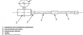
- Install a temporary pipeline line from the filling and pressing devices.
- The section being tested is disconnected from the remaining pipe divisions using plugs with shanks, and is disconnected from the apparatus and equipment. Important: it is prohibited to use the complete shut-off valves of the wire itself for these purposes.
- To test pipelines for strength and density, they are connected to hydraulics (compressors, pumping stations, presses or air networks), creating the pressure required for testing, at a distance of 2 valves.
Hydraulic tests are carried out only under the supervision of the manufacturer or under the guidance of a foreman, in strict accordance with the requirements of technical documentation, instructions and design papers. Gosgortekhnadzor regulations and safety regulations must be observed.
Please note: equipment and test devices (pressure gauges, etc.) undergo mandatory preliminary testing and sealing. The minimum accuracy class of pressure gauges is 1.5 (according to GOST 2405-63), the minimum body diameter is 1.5 cm, the nominal pressure scale is from 4/3 of the measured value. Requirements for the division price of the thermometers used are up to 0.1° C.
Hydraulic tests of water supply and heating pipelines are carried out to study their strength and density. The pressure value during test experiments is established by the design documentation in kgf/cm2:
- steel structures with an operating threshold of up to 4 kgf/cm2 and systems with an operating temperature of more than 400° - 1.5-2;
- steel structures with a working threshold of more than 5 kgf/cm2 - 1.25 (in special cases, the value is calculated using the formula: working load plus 3 kgf/cm2);
- glass, vinyl plastic, cast iron and polyethylene - from 2;
- faolitic – 0.5;
- from non-ferrous metal alloys – 1.
To pump the required loads into the system, mobile plunger, operational and manual (piston) pumps, hydraulic and driven gear presses are used.
Testing
The pipeline is tested for strength and tightness using hydraulics in several stages:
- Connect a hydraulic pump or press.
- Install pressure gauges and fill the structure with water. Important: to control the displacement of air from the pipes, the vents are left open. The water that appears in them indicates that there is no air left inside.
- When filling with water, the surfaces are inspected for leaks, cracks and the slightest flaws in the connecting elements and around the perimeter.
- The required pressure is injected, and the pipeline is tested under prolonged exposure.
- The load is then gradually reduced to standard operating values to re-examine the system state.
- The water is drained from the pipeline, the equipment is removed and disconnected.
Note: glass connections are checked under test loads for 20 minutes; for wires made of other materials, 5 minutes is enough.
During the secondary inspection of steel pipes, special attention is paid to welds and joints. They are carefully tapped with a rounded hammer up to 1.5 kg, retreating 15-20 mm. To test parts made of non-ferrous alloys, a wooden hammer up to 0.8 kg is used; pipelines made of other materials are not tapped to avoid mechanical damage. Hydrotesting of pipelines is considered successful if the pressure gauge did not show a drop in pressure during the tests, and no fogging or leaks were detected in the flange connections, seals and welds. If the results are unsatisfactory, the test is repeated after eliminating them. Note: sometimes for hydraulic tests at sub-zero temperatures, compounds that reduce the freezing point are added to the liquid, pipes are insulated, or the liquid is heated.
Report of hydrostatic or manometric leak test
| ___________________________________________________________________________ (name of the system) installed in ________________________________________________________________________ (name of the facility, ___________________________________________________________________________ building, workshop) _________________________ "__" _________________ 200_. Commission consisting of representatives: customer ___________________________________________________________________ (name of organization, position, initials, surname) general contractor _____________________________________________________ (name of organization , position, initials, surname) of the installation (construction) organization _________________________________________ (name of the organization, position, initials, surname) inspected and checked the quality of installation and drew up this report on the following: 1. Installation was carried out according to the project _______________________________________________ (name of the design organization and drawing numbers ) 2. The test was carried out by _____________________________________________________ (hydrostatic or manometric method) with a pressure of _________________ MPa (_________ kg/cm2) for ______________ min. 3. The pressure drop was __________________ MPa (__________________ kg/cm2) 4. Signs of rupture or violation of the strength of the connection of boilers and water heaters, drops in welds, threaded connections, heating devices, on the surface of pipes, fittings and water leakage through water fittings, flushing devices and so on. not found (cross out what is not needed). Commission decision: Installation was carried out in accordance with the design documentation, current technical specifications, standards, building codes and rules for the production and acceptance of work. The systems are recognized as having passed the pressure leak test. Representative of the customer ____________________________ (signature) Representative of the general contractor ____________________________ (signature) Representative of the installation (construction) organization ___________________________ (signature) |
EXAMPLE OF EXECUTION OF AN ACT FOR INSPECTION OF A HEAT SUPPLY SYSTEM
Certificate of inspection and testing of a heat supply system
| Built-in premises of a residential building at the address: SPCh-65, st. Savushkina , 140 , BS-3 (name of object and address) February 12, 2002 Commission consisting of representatives: Customer ____ JSC "Compatriot" technical supervision engineer Filippov S.V. _____ (name of organization, position, full name) General contractor (general subcontractor) ____ CJSC "Stroitelny Trest" ____ __________________ Deputy. Head of VET Vasilchenko E.I. _____________________ installation organization _______ Otdelstroy LLC plot Semenov P.A. ____ operating organization LLC “Otdelstroy”, head of OJE Odintsov V.A. __ inspected in situ and checked for the thermal effect of the water (steam) heating system performed by __________ Otdelstroy LLC _______________ (name of the installation organization) and drew up this report on the following: 1. Installation was carried out according to the design of __________ JSC LENNIIPROEKT NTO ________ ______________________________ 10188 / DOV 07.2001 ___________________________ (name of the design organization, code of drawings) 2. During the work process, the following deviations from the project were made _______ ___________________________________________________________________________ (list of deviations) agreed with ____________________________________________________________ (position, full name) 3. All heating devices (radiators, convectors, etc.) are evenly heated (to the touch) along the floors and branches of the system 4. The coolant parameters of the heating center at the outside air temperature are: a) coolant temperature in the supply line (primary water 62.2 °C b ) coolant temperature in the return line 28.6 ° C c) coolant temperature after the elevator 43.9 ° C d ) water pressure in the supply line 6.6 MPa . e) water pressure after the elevator is 4.0 MPa . f) water pressure in the return line 3.8 MPa (kgf/cm2) 5 Test duration - 7 hours . Commission decision. The heating system was installed in accordance with the project _____ ____________ JSC "LENNIIPROEKT" NTO 10188 / DOV 07.2001 ________________ ___________________________________________________________________________ Customer representative _____________ S. Filippov (signature) Representative of the general contractor ___________ E. Vasilchenko (signature) Representative of the installation (construction) organization ______________ P. Semenov (signature) Representative of the operating organization ______________ V. Odintsov (signature) |
EXAMPLE OF REGISTRATION OF A THERMAL TEST REPORT FOR A CENTRAL HEATING SYSTEM FOR THE EFFECT OF ACTION
Thermal test report of the central heating system for effect
| Saint Petersburg | "21" April 2003 |
| We, the undersigned: representative of the developer's technical supervision _______ engineer Karpov O.G. ______ work foreman _____ section manager of Otdelstroy LLC Sergin N.P. ___ representative of the operating organization ______________ R. Odintsov ___________ drew up this report stating that the central heating system was tested in building 32A on the street. (prospect) Construction and installation work quarter 81 for the effect of action. Moreover, they established: 1. At the outside air temperature tn = 12 °C, the water temperature in the boilers or control unit t = 105 °C, the temperature in the return line tc = 70 °C, the circulation pressure is 5 m of water. Art., i.e. corresponds to the project. 2. The air temperature in heated rooms, measured at a height of 1.5 m from the floor and at a distance of 1 m from the external walls, was 18 ° C, which corresponds to the standards established for this type of room. 3. All heating devices in the heating system heat up evenly. | |
| Author of the project or representative of the operating organization | ___________R. Odintsov (signature) |
| Representative of the developer's technical supervision | ____________O. Karpov (signature) |
| Producer of works | ___________N. Sergin (signature) |
Form of hydrostatic testing report for low-pressure boilers (water heaters, boiler auxiliary equipment, fuel oil pipelines)
Certificate of hydrostatic testing of low pressure boilers (water heaters, boiler auxiliary equipment, fuel oil pipeline)
| ___________________________________________________________________________ (name of object and address) _________________ "__" ____________ 200_ Commission consisting of representatives: customer __________________________________________________________________ (name of organization, position, full name) general contractor ___________________________________________________ (name of organization, position, full name) o.) installation organization ______________________________________________________________ (name of organization, position, full name) inspected and checked the quality of installation __________________________________ (characteristics and number of boilers, water heaters, ___________________________________________________________________________ equipment and pipelines) performed by _______________________________________________________________ (name of installation organization) and drew up an act as follows: 1. Installation was carried out according to the project _______________________________________________ ______________________________________________________________________________ (name of the design organization and number of drawings) 2. During the work process, the following deviations from the project ___________________________________________________________________________ (list of deviations) agreed with ____________________________________________________________ (position, full name) 3. Boilers (water heaters, boiler auxiliary equipment, pipelines) were tested by the hydrostatic method with a test pressure of _________ MPa (________ kgf/cm2) for 5 minutes. 4. During the time spent under test pressure, no pressure drop was observed. 5. During the time spent under the maximum operating pressure of __ MPa (___kgf/cm2), no signs of rupture or visible deformation of the boiler parts were detected; no drops or sweating were observed in the nipple and weld seams. Commission decision: Boilers (water heaters, boiler auxiliary equipment, pipelines) are recognized as having passed the hydrostatic test. Customer representative ___________________ ____________ (signature) (full name) Representative of the general contractor ________________ _______________ (signature) (full name) Representative of the installation organization _________________ ______________ (signature) (full name) |
Form of test report for internal sewerage and drainage systems (SNiP 3.05.01-85, Appendix 4)
Test report for internal sewerage and drainage systems
| ___________________________________________________________________________ (name of the system) installed in ________________________________________________________________________ (name of the facility, ___________________________________________________________________________ building, workshop) _________________________ “__” _________________ 200_ Commission consisting of representatives: customer ___________________________________________________________________ (name of organization, ___________________________________________________________________________ position, initials, surname) general contractor ___________________________________________________________________________ (name organization, ___________________________________________________________________________ position, initials, surname) of the installation (construction) organization _________________________________________ (name of the organization, ___________________________________________________________________________ position, initials, surname) inspected and checked the quality of installation performed by the installation department, and drew up this report on the following: 1. Installation was carried out according to the project _____________________________________________ (name of the design organization ___________________________________________________________________________ and numbers of drawings) 2. The test was carried out by spilling by simultaneously opening ____ sanitary fixtures connected to the tested area for _______ minutes, or by filling with water to the height of the floor (cross out unnecessary ones). 3. During inspection during testing, no leaks were found through the walls of the pipelines and joints. Commission decision: Installation was carried out in accordance with the design documentation, current technical specifications, standards, building codes and rules for the production and acceptance of work. The systems are recognized as having passed the pressure leak test. Representative of the customer ________________________ (signature) Representative of the general contractor ________________________ (signature) Representative of the installation (construction) organization ________________________ (signature) |
EXAMPLE OF EXECUTION OF A TESTING REPORT FOR INTERNAL SEWERAGE AND DRAINAGE SYSTEMS
Pneumatic testing
When it is necessary
Pneumatic testing of pipelines is also used to test their density and strength or only density (in this case, a hydraulic strength test is carried out first; ammonia and freon products are not hydraulically tested). It is used in cases where hydraulic studies are impossible for objective reasons:
- there is a requirement to use inert gases or air during testing;
- air temperature is negative;
- there is no water in the working area;
- There is too much stress in the pipeline and supporting structures due to the weight of the water.
To carry out pneumatic testing of pipelines according to SNiP, air or inert gas is used. Mobile compressors or a compressed air network are used. Requirements for the length of divisions and pressure in kgf/cm2 during testing:
- with a diameter of less than 2 cm - 20 (length of the internal segment - 100 m, external - up to 250 m);
- with a diameter of 2-5 cm - 12 (length of the internal segment - 75 m, external - 200 m);
- if the diameter exceeds 5 cm - 6, with the length of the internal segment - 50 m, external - 150 m.
In special cases, if the project requires it, the use of other values is allowed. Tests are also carried out in strict accordance with design documentation and safety instructions, developed individually.
Important: above-ground structures made of cast iron, glass and faolite pipelines do not pass pneumatic tests. If cast iron fittings are installed on steel systems (with the exception of parts made of ductile cast iron), testing with air and inert gas is allowed if the pressure is below 4 kgf/cm2. Pre-cast iron parts undergo mandatory strength tests using water (requirement GOST 356-59).
Work order
- Filling the pipeline with gas or air.
- Increasing pressure, inspecting the area being tested when it reaches 0.6 of the maximum test value - for structures with a working indicator up to 2 kgf/cm2, 0.3 and 0.6 - if the working indicator exceeds 2 kgf/cm2. Important: during inspection, it is prohibited to increase the load or hit surfaces under load with a hammer.
- The final inspection occurs under operating loads.
The tightness of joints, welds, seals and flanges is measured by applying a soap solution. To test systems that transport poisonous, flammable and toxic substances at temperatures above their boiling point, a pipeline leak test requires an additional tightness test. To do this, in parallel with the main indicators, the pressure drop is studied. All equipment connected to the system for transporting the listed types of substances is also checked. If the pressure on the pressure gauge did not decrease during testing, and no leaks or sweating were detected in the connecting seams and seals, the result is considered satisfactory.
Only qualified employees who have undergone instructions and have the appropriate skills are allowed to test pipelines and evaluate its results. A timely and thorough check of communications will protect you from accidents, breakdowns and losses.
Source
How to draw up a pressure test report for a precision air conditioning system?
Hydraulic tests are carried out to check the tightness of the system by test pressure, including all elements. Before performing pressure testing, the line is evacuated in order to get rid of excess moisture in the system.
After evacuation, high-purity nitrogen (additionally purified from carbon-containing compounds) is loaded into the system, and the pressure is set according to the formula:
Maximum permissible pressure x 1.25 bar= …..
In the report, the obtained indicator is recorded as pressure testing. It should be taken into account that the pressure for the strength test depends on the category of the pipe and the maximum permissible pressure indicated on the equipment nameplate.
This process is maintained for a day. If the pressure difference does not exceed 1 bar, then there are no leaks in the system.
The test results are recorded in the equipment passport, and a hydrostatic or manometric leak test report is drawn up.
The main points that the act must contain:
- When was the act drawn up (date and time)
- The organization that carried out the installation and crimping work
- Composition of the commission from the customer
- Crimping pressure
Below is a sample act
HYDROSTATIC OR MANOMETRIC TEST REPORT
FOR TIGHTNESS No.___
Moscow "__" ______ 202_g.
Data center cooling system _____________________________________________________________________________________________________ (system name)
_____________________________________________________________________________________________________ (name of object, building, workshop)
Commission consisting of:
- Company, position, full name
- Company, position, full name
inspected the work performed
______________________________________________________________________________________________ (name of construction and installation organization)
and drew up this act as follows:
1._________________________________________________________________________
(pressure test results with detailed description)
2. Test carried out: _____________________________________________________
(hydrostatic or manometric method)
Pressure __ MPa (__ kgf/cm)
within__ hours
The pressure drop was: _ MPa (__kgf/cm)
Commission decision: __________________________________________________________________________________________
_____________________________________________________________________________________________________
(The system is recognized as having passed the pressure leak test or not)
The act was drawn up in 2 copies
Representatives:
_______________________________________________________________________________________________
(position, surname, initials, signature)
_______________________________________________________________________________________________
(position, surname, initials, signature)
Pressure testing (pressure testing) of heating and water supply system pipes.
Reproduction of articles, as well as their individual parts, is prohibited. We want to reserve the right to exclusive placement of this material on our website. Here we share the knowledge and experience gained by our team over the years of work in the field of design and installation of engineering systems.
Introduction What is crimp testing (pressure testing) of pipelines and connections Description of the general procedure for crimping pipes Uponor Methodology for PEx cross-linked polyethylene pipes. Water test Uponor method for PEx-Al-PEx metal-plastic pipes. Water test Uponor procedure for PEx and PEx-Al-PEx pipes. Air test Uponor notes for testing underfloor heating pipes (underfloor heating) Rehau method for testing heating pipes, underfloor heating and water supply HERZ recommendations (DIN 4725) for hydraulic testing of underfloor heating systems KAN method for testing heating pipes (including water underfloor heating) ) and water supply system for tightness STB 2038-2010. Methodology for testing a heating system for tightness using the hydrostatic method (pressure testing with water) STB 2038-2010. Methodology for testing a heating system for tightness using the manometric method (air pressure testing) STB 2001-2010. Methodology for testing water supply systems for tightness using the hydrostatic method (pressure testing with water) STB 2001-2010. Methodology for testing a water supply system for tightness using the manometric method (air pressure testing) Conclusion
Introduction. up
The purpose of this article is to describe the procedures for pressure testing (pressure testing) of installed pipes and connections of the heating and water supply system to check the quality of the work performed. The general principles of the hydrostatic (water pressure testing) and manometric (air pressure testing) methods are described. Specific recommendations from leading manufacturers of polymer pipelines, which are often used in the installation of heating and water supply in private homes, are considered: Uponor, Rehau, Herz, Kan. Sets out local codes and regulations regarding pressure testing.