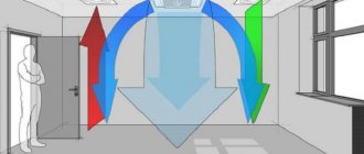
Why do they measure air speed?
For ventilation and air conditioning systems, one of the most important factors is the condition of the supplied air. That is, its characteristics.
The main air flow parameters include:
- air temperature;
- air humidity;
- air flow rate;
- flow rate;
- duct pressure;
- other factors (pollution, dust...).
SNiPs and GOSTs describe standardized indicators for each of the parameters. Depending on the project, the values of these indicators may vary within acceptable standards.
The speed in the air duct is not strictly regulated by regulatory documents, but in the designer's reference books you can find the recommended value of this parameter. You can find out how to calculate the speed in an air duct and become familiar with its permissible values by reading this article.
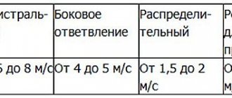
For example, for civil buildings the recommended speed of air movement through the main ventilation ducts is within 5-6 m/s. A correctly performed aerodynamic calculation will solve the problem of supplying air at the required speed.
But in order to constantly maintain this speed regime, you need to control the speed of air movement from time to time. Why? After some time, air ducts and ventilation channels become dirty, equipment may malfunction, and air duct connections become depressurized. Also, measurements must be carried out during routine inspections, cleanings, repairs, and in general, during ventilation maintenance. In addition, the speed of movement of flue gases, etc., is also measured.
What device measures air speed?
All devices of this type are compact and easy to use, although they have their own subtleties.
A device for measuring air speed is called an anemometer
Instruments for measuring air speed:
- Vane anemometers
- Temperature anemometers
- Ultrasonic anemometers
- Pitot tube anemometers
- Differential pressure gauges
- Balometers
Vane anemometers are one of the simplest devices in design. The flow rate is determined by the rotation speed of the device impeller.
Temperature anemometers have a temperature sensor. When heated, it is placed in the air duct and as it cools, the air flow rate is determined.
Ultrasonic anemometers mainly measure wind speed. They work on the principle of determining the difference in sound frequency at selected control points of the air flow.
Pitot tube anemometers are equipped with a special small diameter tube. It is placed in the middle of the duct, thereby measuring the difference in total and static pressure. These are one of the most popular devices for measuring air in an air duct, but they have the disadvantage of being unable to be used in high dust concentrations.
Differential pressure gauges can measure not only speed, but also air flow. Complete with a pitot tube , this device can measure air flows up to 100 m/s.
Balometers are most effective when measuring air velocity at the outlet of ventilation grilles and diffusers. They have a bell that captures all the air coming out of the ventilation grille, thereby reducing measurement error to a minimum.
Everything you need to know about mass air flow sensors
A mass air flow sensor is necessary for the engine, or more precisely the electronic engine control unit, to correctly calculate the amount of fuel injected. Let us immediately note that mass air flow sensors have long been used on all gasoline engines with electronic injection, as well as on later diesel engines meeting environmental standards Euro-4 and higher. But the tasks performed are different. Diesels need a mass air flow sensor primarily so that the ECU can correctly calculate the volume of recirculated exhaust gases supplied.
For gasoline engines, a mass air flow sensor is extremely necessary to maintain a stoichiometric mixture. Let us recall that for successful and complete combustion of a mixture of air and gasoline, their proportion by weight should be 14.7 to 1. That is 14.7 kg should account for 1 kg of fuel. With this proportion, all combustion products generated by the engine are neutralized by the catalyst.
If the fuel mixture is rich, then the exhaust gases will contain a lot of both unburned fuel (hydrocarbons) and carbon monoxide (CO, carbon monoxide).
If the fuel mixture is lean, then excess oxygen, which is not involved in fuel oxidation, combines with nitrogen. Let us remember that the air we breathe and which enters the cylinders consists of 78% nitrogen. Under combustion chamber conditions, oxygen oxidizes nitrogen, resulting in the formation of nitrogen oxides, which cause a lot of harm to the environment.
Let's make a small lyrical digression and note that the engine control unit does not adhere to the stoichiometric mixture in all modes. For example, during acceleration, the control unit deliberately “riches” the mixture a little to ensure a sufficient volume of fuel vapor. Let us add that during acceleration, readings from lambda probes are also not taken into account. Also, during warm-up, to compensate for poor fuel evaporation, the engine runs on a rich mixture without taking into account lambda regulation.
On our YouTube channel you can watch a video review about mass fuel flow sensors.
You can select and buy a mass air flow sensor (MAF sensor) for the car model you are interested in in our used spare parts catalog.
A LITTLE ABOUT DAD
Absolute pressure sensors are also used to measure air flow. They are installed in the intake manifold and work in conjunction with an air temperature sensor. On naturally aspirated engines, based on the vacuum in the intake manifold, these sensors measure the amount of air actually entering the cylinders. Alone, i.e. without mass air flow sensor, they are used on simple gasoline engines and, by the way, provide faster throttle response, because located close to the intake valves.
In combination with mass air flow sensors, absolute pressure sensors are necessarily used on turbocharged engines. They are simple and very reliable; they can only suffer from soot and oil deposits, but are easy to clean.
You can select and buy an absolute pressure sensor (MAP, MAP sensor) for the car model you are interested in in our catalog of used spare parts.
MAIN TYPES OF FLOW METERS
So, to measure the mass of air entering the engine, a mass air flow sensor is used. There are two main types of “flow meters” used on motors. These are sensors with a thread and a film sensitive element. They work according to approximately the same scheme: they measure the volume of air passing through a heated element.
In a mass air flow sensor with a thread, the sensitive element is a thin wire (thread) made of platinum. It is located in the intake tract after the air filter and before the throttle valve in the air flow. The current heats the thread, the air cools it. The thread temperature is always maintained at 120°...150° above the temperature of the passing air. How does a heated wire measure the mass of passing air?
Everything is very simple. The electrical resistance of the thread depends on its temperature, and the temperature is “knocked down” by the air flow. Consequently, by maintaining the temperature of the filament with an electric current, we can draw a conclusion about the volume of air passing through the intake tract. Actually, the readings from the mass air flow sensor with a heated filament are voltage values. The voltage readings are transmitted to the control unit in the form of output voltage. Next, the ECU, based on the values programmed in the program, recalculates the Volts into the volume of oxygen entering the combustion chambers.
The mass flow sensor with a filament has been replaced by a film sensor, also known as a hot-wire sensor. It appeared in the early 1990s as a more accurate air mass meter and is still used today. A sensing element with two thermistors and a heating resistor between them. It also has an air temperature sensor, which further increases its accuracy.
A film mass air flow sensor works very simply: the air flow passes along thermistors (each of which is evenly heated), cools the first thermistor, and the air reaches the second one already heated. As a result, the temperature difference between the thermistors and the associated difference in electrical resistance are recorded, which is recorded by the electronics. This measures the volume of air passing through. Because Since the film mass air flow sensor has two sensitive thermistors, they are capable of measuring both forward and reverse air flow.
PROS AND CONS OF DMRV OF TWO TYPES
A mass air flow sensor with a heated filament is simple, unpretentious, but inaccurate. The accuracy of air mass measurement is not very high; it also does not take into account the reverse air flow, which is why a lean fuel assembly is formed in some modes. Engines with such a sensor do not meet Euro-4 and even Euro-3 environmental standards. But nothing happens to such a sensor; it is not even afraid of contamination.
To maintain heat transfer, when the ignition is turned off, a high voltage is applied to the filament, heating the filament to 500 degrees for several seconds. At the same time, all the dust and soot that settles on it burns. If such self-cleaning is not enough, the MAF filament can be perfectly cleaned with special means.
Film mass air flow sensors are capable of measuring reverse air flow, which is almost constantly present during engine operation. Backflow occurs when air is reflected from closed intake valves. Reverse flow is measured simply: when the sensing elements are cooled in the opposite direction, i.e. from the engine to the filter. However, with the reverse flow towards the mass air flow sensor, soot, oil vapors and other dirt produced by the engine fly. There are cases of debris and even insects getting onto the sensitive element through an old or poor-quality air filter.
SYMPTOMS OF A FAULTY MAF
A film mass air flow sensor with a sensitive element covered in dirt begins to lie. The problem with contamination is very serious and it cannot be cleaned.
If the sensor is lying, then the engine control unit selects an inadequate amount of fuel and sets the incorrect ignition timing. As a result, engine operation is disrupted. The car stalls, pours a lot of fuel or does not start at all due to fuel overflow.
The engine will operate relatively normally with a completely faulty or disconnected mass air flow sensor. If there is no signal from the flow meter, then the engine control unit uses a calculated air mass model, which is used precisely in the event of a complete malfunction of the mass air flow sensor.
HOW TO CHECK DMRV?
Let us mention once again that a mass air flow sensor with a thread, as long as it is intact, usually does not cause any problems and, in extreme cases, can be easily cleaned with non-contact cleaning agents. A working mass air flow sensor with the ignition on and the engine not running produces a voltage of 1 Volt. This voltage can be measured with a multimeter between the two signal wires. Typically these are wires 3 and 5 (on Bosch sensors) or 3 and 4 on Denso sensors. If the voltage is above 1.03 Volts, then it is already lying, but most likely, cleaning the thread can restore the accuracy of its readings.
In the same way, you can check the removed sensor without the car. You just need to apply 12 volts to it to power it through the appropriate wires.
Capricious film mass air flow sensors can be checked with a multimeter. The manufacturer itself, Bosch, recommends checking the quiescent voltage with the engine off and the ignition on: the voltage should be exactly 1 Volt. The difference can be up to 0.02 Volts. If the voltage on the mass air flow sensor is less than 0.98 Volts, then it definitely needs to be replaced. If the voltage is more than 1.02 Volts, then the mass air flow sensor most likely needs to be changed. The fact is, as practice shows, a mass air flow sensor with a voltage of up to 1.3 Volts can turn out to be serviceable, and at the same time, with a voltage of the correct 1 Volt, it can be faulty.
This check must be combined with the second method. The second method involves measuring the peak voltage. But there are nuances here. If the engine is equipped with a cable-operated throttle valve, you must manually open the throttle sharply with the engine idling. In this case, on a working mass air flow sensor, the voltage will jump to 4 Volts or more. If the voltage is less than 4 Volts, then the mass air flow sensor is definitely faulty. True, this method is not suitable for diagnosing turbo engines, where the acceleration of the air flow occurs with a noticeable delay and may not increase to peak values when the vehicle is on the gas while the vehicle is stationary.
On motors with an electronic throttle, the check is performed in the same way, but there are two nuances. Firstly, you can only open the throttle by pressing the accelerator. Secondly, you need to know exactly the peak voltage of a particular working mass air flow sensor during such a test. This value can be lower than 4 Volts. Those. the actual value must be measured with some correct value that you know from practice or from the recommendations of the car manufacturer.
The most modern film flow meters (type HFM6) supply a digital frequency signal to the ECU. It is impossible to assess the performance of such a flow meter by checking the voltage. True, such sensors are well diagnosed by built-in tools, and errors appear indicating a weak signal from the flow meter.
Features of air speed measurements
There are some nuances of working with different types of anemometers. As already mentioned, pitot tube anemometers cannot be used at high concentrations of solid particles, otherwise the tube will quickly become clogged and the instrument will fail. Thermal anemometers do not work in conditions of measuring high air flow velocities - over 20 m/s. When measuring speed in heated air flows (for example, in gas ducts), it is recommended to use a tube made of stainless steel rather than plastic.
How measurements are taken
Air velocity measurements can be made in ducts, at duct outlets, at ventilation grilles or diffusers.
When the speed measurement is carried out directly in the air duct, the measurement location should be located after the flow passes through the filters. You should find a special hole on the air duct, which is intended for control and measuring operations (such holes are often closed with a pitometer plug). You can also use a cleaning hatch.
Organization of air flow measurements in the air duct
The process of measuring air speed using a probe.
Before you start measuring directly in the air duct, you must make sure that there is a working hole in the pipe wall intended for control and measuring operations. Its diameter must exactly match the diameter of the probe.
It is important to accurately select the location for measurements. In particular, the specified hole should be drilled on a straight section of the air duct, the length of which should be at least 5 pipe diameters. In this case, the hole itself must be positioned in such a way that the distance to it is equal to 3 diameters, and after it – 2 diameters of the air duct.
In contrast to measurements on the ventilation grille, when measuring air flow inside the duct, it is recommended to use vane anemometers with a small diameter impeller (16-25 mm). For this operation, hot-wire anemometers and differential pressure gauges equipped with a pneumometric tube are also used.
It should be noted here that differential pressure gauges are not suitable for taking measurements in air ducts through which an air mass passes at a deliberately low speed (less than 2 m/sec). In this case, it is necessary to use a hot-wire anemometer or a vane anemometer.
If the air duct is located quite high in the room (for example, under the ceiling of the room), it is recommended to use a probe with a telescopic handle or a probe extension. If a pneumometric tube is used for measurements, its length should be selected in advance, taking into account the height of the measurement point.
METHOD FOR SELECTING MEASUREMENT POINTS
1.1. To measure pressures and air velocities in air ducts (channels), areas must be selected with measuring sections located at distances of at least six hydraulic diameters D h, m behind the place of flow disturbance (bends, dampers, diaphragms, etc.) and at least two hydraulic diameters in front of it.
In the absence of straight sections of the required length, it is allowed to place the measuring section in a place dividing the section selected for measurement in a ratio of 3: 1 in the direction of air movement.
Note. The hydraulic diameter is determined by the formula
where F, m 2 and P, m, respectively, are the area and perimeter of the section.
1.2. It is allowed to place a measuring section directly at the point of sudden expansion or contraction of the flow. In this case, the size of the measuring section is taken to correspond to the smallest cross section of the channel.
1.3. The coordinates of pressure and velocity measurement points, as well as the number of points, are determined by the shape and dimensions of the measuring section according to the lines. 1 and 2. The maximum deviation of the coordinates of the measurement points from those indicated on the drawings should not exceed ±10%. The number of measurements at each point must be at least three.
Coordinates of pressure measurement points
and velocities in air ducts
Coordinates of pressure and velocity measurement points
in rectangular air ducts
1.4. When using anemometers, the measurement time at each point should be at least 10 s.
Measuring movement speed and calculating air flow (thrust) in channels
The places (points) for measuring the speed of air movement in the ventilation ducts are shown with green arrows - in the room , in the cross section of the entrance grille, as well as at the head (at the mouth) of the channel.
Measuring the speed of air movement, followed by calculating the flow rate of the removed air, is carried out for each ventilation channel in two points (clause 11.16.2 GOST 34060-2017):
- indoors, in the cross section of the entrance grille;
- at the head (at the mouth) of the canal.
The amount of air flow in the room, in the cross section of the entrance grille, is used to determine the effectiveness of natural ventilation.
Based on the difference in air flow rates in the room and at the head of the duct, the degree of tightness of the ventilation duct is assessed .
Requirements for methods (methods) of ventilation measurements (clause 10 of GOST 34060-2017)
All measurements should be performed in accordance with approved measurement procedures, as well as in accordance with the requirements of this standard.
The measuring instruments used must have certificates of approval of the type of measuring instruments and documents on their verification (calibration).
Determination of movement speed and air flow in ventilation ducts (clause 10.4 of GOST 34060-2017)
Measuring the speed of air movement in natural ventilation channels is carried out during cold or transitional periods of the year when the outside air temperature is not higher than 5 °C and the difference between the external (outdoors) and internal (indoors) temperatures is not less than 15 °C (clause 11.16.2 GOST 34060-2017).
Air speed in air ducts, channels and openings should be measured with electronic anemometers:
- hot-wire anemometer with a “heated string” probe for measuring velocity in ducts and air ducts ;
- impeller with an impeller probe for measuring the speed of air flow from air distribution and air intake devices .
In holes with an area of up to 1 m2, it is necessary to measure air speed with a slow, uniform movement of the anemometer across the entire cross-section of the hole.
At each measurement point, the velocity should be measured twice, and the difference between the measurement results should be no more than 5%, otherwise additional measurements should be performed, and the flow velocity should be determined as the arithmetic mean of all measurements taken.
Measurements of air flow velocity in open holes should be made in the plane of the air exit (for air distribution devices), and when air enters the hole - inside the channel (for air intake devices).
In openings covered with grilles , measurements of air flow velocity should be performed with an anemometer equipped with a special attachment. When taking measurements, the nozzle must be in close contact with the grid . A custom nozzle can be made from sheet steel or plastic.
When choosing an anemometer, it is desirable that it have a function for calculating volumetric flow, as well as averaging over time and the number of measurements. Such devices make work easier - they automate the process of calculating air flow parameter values. Otherwise, you will have to calculate these values yourself.
Measurements of the dimensions of ventilation ducts to calculate the cross-sectional area are performed with a tape measure.
Determination (calculation) of the air flow rate in the ventilation duct
Air flow L, m3/h, in open openings should be determined by the formula: L = 3600* V* F , where V is air speed, m/s; F is the area of open openings of air intake and air distribution devices with a constant direction of air movement, m2.
Air flow L, m3/h, in channel openings closed with grilles should be determined by the formula: L = 3600* V* fw , where V is the measured air speed, m/s; fw is the live section of the grille, the cross-section of the opening minus the area of the grille, m2.
The live cross-section can be found on the website of the grating manufacturer, if known. Or by measuring the size of the holes and then calculating their total cross-sectional area.
The calculated value of air flow in the channel is compared with the minimum permissible value of air flow in this channel, specified in the design documentation or in the ventilation passport of the house/apartment. Based on the comparison results, a conclusion is made about the suitability of the channel for operation in terms of air flow .
Measuring the volume flow at the air intake grille of the exhaust ventilation
To carry out measurements on the ventilation grille, an anemometer with a large diameter impeller D = 80-125 mm is used For such a device, the diameter of the impeller will be comparable to the dimensions of the grille.
Anemometer with a remote impeller with a diameter of 100 mm. The optional funnel set allows you to measure on ventilation grilles with maximum efficiency.
An anemometer with a large diameter impeller D=80-125 mm is the most suitable device, since the minimum number of measurements is carried out with it. This gives a more accurate result and a minimum of time spent.
Air moves through the grille from different directions. Not all air flows pass through an anemometer placed on the grid, which increases the measurement error.
To simplify measurements on the grid and reduce errors, a special attachment, a funnel, is used together with the anemometer.
Installing a funnel on the ventilation grille creates a uniform air flow in the anemometer measurement area.
After installing the funnel with an anemometer on the ventilation grille (diffuser), as shown in the figure, a uniform air flow will be directed directly at the sensitive element of the device, due to which the average speed will be measured.
When using a device with an impeller complete with a funnel, there is no need to take multiple measurements, which gives more accurate measurement results and saves time. Only one measurement is taken.
Measuring the air speed on the grate using a hot-wire anemometer or an anemometer with a small-diameter impeller (16-25 mm) can only be done using a special attachment - a funnel. Without a funnel, the accuracy of measurements with these devices is not ensured.
For measurements on air intake grilles of exhaust ventilation, the nozzle can be in the shape of a rectangular box . A custom nozzle can be made from sheet steel or plastic.
When taking measurements, the nozzle must be in close contact with the grid.
Anemometers with a volume flow calculation function display it automatically. It should be taken into account that each funnel has its own conversion factor , which must first be entered into the device.
In this video, a professional adjuster will show you how to properly check the efficiency of ventilation in a house or apartment.
Measuring the air flow rate at an open ventilation duct opening
To measure the speed of air flow at the open hole of the ventilation duct, anemometers are used:
- Thermal anemometer.
- Impeller with an impeller diameter of 16-25 mm.
Distribution of measurement points in rectangular and round sections of the air duct (channel) according to GOST 12.3.018-79.
First, it is necessary to measure the flow velocity at several points distributed across the channel cross-section, as shown in the figure. Next, calculate the average speed using the formula:
where Vi [m/s] is the speed value of one measurement, n is the number of measurements.
Then, calculate the volumetric flow rate using the formula:
L = Vav x F x 3600 [m3/h],
where Vav [m/s] is the average flow velocity, F [m2] is the cross-sectional area of the channel in the measured area.
When taking measurements , it is necessary that the sensitive element of the probe is directed strictly towards the air flow . When deviating from this axis, the measurement error increases, and the larger the deviation angle, the greater the error.
Checking the tightness of ventilation channels and air ducts
If the design documentation does not contain requirements for the tightness of air ducts and information about the tightness class, tightness should be ensured according to the permissible loss value (clause 7.3 of GOST 34060-2017).
Allowable losses or leaks of air in the system should not exceed 8% of the air flow of the air duct (clause 7.5 of GOST 34060-2017).
To check the tightness (isolation, density of masonry) of the natural ventilation channel, compare the results of determining the air flow at the beginning of the channel (in the room, in the cross section of the entrance grille) and at the end of the channel (at the head).
If the channel is sealed, then the air flow rate at the beginning and at the end of the channel will not exceed the permissible loss value: 8% (clause 7.3 of GOST 34060-2017).
Based on the comparison results, a conclusion is made about the suitability of the channel for operation according to the “channel tightness” indicator .
If the tightness of the canal does not meet the specified requirements, then the canal walls are examined along the entire length using a video camera. Detected defects are eliminated. After repair, the channel is again checked for leaks.
EQUIPMENT
2.1. For aerodynamic tests. ventilation systems must use the following equipment:
a) combined pressure receiver - for measuring dynamic flow pressures at air speeds of more than 5 m/s and static pressures in steady flows (Fig. 3);
b) total pressure receiver - for measuring total flow pressures at air speeds of more than 5 m/s (Fig. 4);
c) differential pressure gauges of accuracy class from 0.5 to 1.0 according to GOST 11161-71, GOST 18140-77 and draft meters according to GOST 2648-78 - for recording pressure differences;
d) anemometers in accordance with GOST 6376-74 and hot-wire anemometers - for measuring air velocities less than 5 m/s;
e) barometers with an accuracy class of at least 1.0 - for measuring pressure in the environment;
g) psychrometers with an accuracy class of at least 1.0 according to GOST 6353-52 and psychrometric thermometers according to GOST 15055-69 - for measuring air humidity.
The main dimensions of the receiving part of the combined
* Diameter d should not exceed 8% of the internal diameter of a round or width (according to internal measurement) of a rectangular duct.
2.2. The designs of instruments used to measure velocities and pressures of dust-laden flows must allow them to be cleaned from dust during operation.
2.3. To carry out aerodynamic tests in fire and explosion hazardous industries, instruments must be used that correspond to the category and group of production premises.
Main dimensions of the receiving part of the receiver
* Diameter d should not exceed 8% of the internal diameter of a round or width (according to internal measurement) of a rectangular duct.
PREPARATION FOR TESTS
3.1. Before testing, a test program must be drawn up indicating the purpose, operating modes of the equipment and test conditions.
3.2. Ventilation systems and their elements must be checked and any detected defects must be eliminated.
3.3. Indicating instruments (differential pressure gauges, psychrometers, barometers, etc.), as well as communications to them, should be located in such a way as to exclude the influence of air flows, vibrations, convective and radiant heat on them, which affect the instrument readings.
3.4. Preparation of devices for testing must be carried out in accordance with the passports of the devices and the current instructions for their operation.
PROCESSING OF MEASUREMENT RESULTS
5.1. Based on the values measured in accordance with the program, determine:
relative humidity of transported air j, %;
density of transported air p, kg/m 3 (kgf s 2 /m 4);
air velocity v, m/s;
air flow L, m 3 /s;
loss of total pressure in the ventilation network or in its individual elements D р, kPa (kgf/m2);
pressure loss coefficient of the ventilation network or its element z.
5.2. The relative humidity of the transported air is determined by the readings of dry and wet thermometers in accordance with the device data sheet.
5.3. The density of the transported air is determined by the formula
where p' is the static or total pressure of the flow, measured by a combined pressure receiver or a total pressure receiver at one of the points of the measuring section;
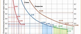
K j is a coefficient depending on the temperature and humidity of the air being moved. The value of K j is determined from the table. 1.
Dependence of the coefficient K j on the temperature and humidity of the transported air
Source
Operating principle of air flow meters
The operating principle of Vortex RNG and Vortex RWG/RWBG is similar to that of most vortex air flow meters. The device consists of an air flow measurement sensor and an electronic logic device. The sensor consists of two sensitive elements - a blimp body and a piezoelectric sensor, which are placed inside the pipeline. The bluff body is in the path of the air (gas) flow. Passing through it, the air flow forms a path of turbulence. The frequency of turbulence depends on the volumetric quantity and intensity of air flow. The flow meter is equipped with a piezosensor that responds to changes in air flow; installed behind the bluff body, it detects these turbulences and transmits a signal to the electronics. Next, the electronics perform mathematical operations and display the current air flow on the flow meter display.
The operating principle of the Hedland H-series 1500 PSI rotametric air flow indicator is quite simple. The device consists of a metal case containing a capsule with a measuring scale and an indicator float. The position of the float in the capsule depends on the volumetric air flow. Moving along the capsule with a scale and taking a certain position, the indicator informs the technical staff about the air flow value.