The importance of air exchange
Depending on the size of the room, the air exchange rate should be different.
The task of any ventilation is to ensure an optimal microclimate, humidity level and air temperature in the room. These indicators affect a person’s comfortable well-being during work and rest.
Poor ventilation leads to the proliferation of bacteria that cause respiratory tract infections. Food products begin to spoil quickly. Increased humidity levels provoke the appearance of fungus and mold on walls and furniture.
Fresh air can enter the room naturally, but compliance with all sanitary and hygienic indicators is possible only with a high-quality ventilation system. It must be calculated for each room separately, taking into account the composition and volume of air, design features.
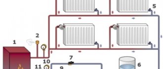
For small private houses and apartments, it is enough to equip shafts with natural circulation of air flows. But for industrial premises and large houses, additional equipment is required in the form of fans that provide forced circulation.
When planning a building for an enterprise or public institution, the following factors must be taken into account:
- high-quality ventilation should be in every room;
- it is necessary that the composition of the air complies with all approved standards;
- enterprises require the installation of additional equipment that will regulate the air speed in the air duct;
- For the kitchen and bedroom it is necessary to install different types of ventilation.
In order for the air exchange system to meet all requirements, it is necessary to calculate the air speed in the air duct. This will help you choose the right device.
Determination of air speed
The speed of air movement is determined by an ASO-3 anemometer, which allows you to measure the speed of air movement within the range of 0.3..5.0 m/s, or a ball catathermometer to measure low speeds of air movement.
The vane anemometer (Fig. 3) operates on the principle of air pressure acting on the impeller of anemometer 1; in this case, before the measurement, the arrester 7 is turned off and the initial position of the counter is recorded (on all scales 4, 5, 6) - K1; install the device in the air flow and achieve the greatest rotation of impeller 1; after 10...15 seconds, turn on the arrester 7 and the stopwatch for the time t of the experiment (50...100 sec); after the expiration of the experiment, arrester 7 is turned off and the readings of the counter – K2 – are recorded.
After this, determine the number of divisions (n) per unit of time using the formula:
,
Rice. 3. Vane anemometer ASO-3:
1 – impeller; 2 – handle; 3 – unit scale arrow; 4 – scale of units; 5 – thousand scale; 6 – hundreds scale; 7 – arrester
and using a calibration graph (Appendix 3) determine the speed of air movement.
Low air speeds are also determined using a catathermometer (Fig. 4). Before measurements, the lower reservoir of the device is heated in hot water at a temperature of 60...70 °C until two-thirds of its upper reservoir is filled. Then wipe the lower reservoir dry, hang the catathermometer at the research point and use a stopwatch to record the cooling time of the device from 38 to 35 °C. After this, the cooling force of the air (N) is found, expressed in millicalories per second using the formula:
,
where F is the factor of the device, indicated on its body; τ – cooling time of the device from 38 °C to 35 °C, sec.
Figure 4. Ball catathermometer:
1 – lower reservoir; 2 – instrument scale; 3 – upper reservoir.
Then calculate the difference between the average catathermometer temperature of 36 °C and the air temperature Q and find the H/Q ratio. The speed of air movement is determined using the table (Appendix 4). This device is not recommended for use at air temperatures above 29 °C and in the presence of thermal radiation near cooled surfaces.
You can measure air temperature using either a conventional mercury thermometer or a dry thermometer-psychrometer.
When studying meteorological conditions it is necessary:
a) measurements should be taken in the working area and at various points in the room (working area) at a level of 1 m from the floor - when working while sitting and at a level of 1.5 m - when working while standing;
b) take measurements at different times of the day (beginning, middle and end of the work shift) and at different times of the year;
c) measurements should be carried out at both permanent and non-permanent workplaces at their minimum and maximum distance from sources of local heat release, moisture release, cooling (heated equipment, windows, doors, gates, open containers with liquid, etc.);
d) at the time of measurement, note the features of the technological process, the state of the workroom and ventilation.
Control questions;
1. What is relative humidity?
2. What factors influence the microclimate of working premises?
3. What is effective temperature?
4. What is called equivalent effective temperature?
5. Comfort zone and line. The essence of these concepts.
6. What effect does air speed have on a person’s well-being;
7. What are the optimal microclimate parameters in the workroom, what do they depend on?
8. Explain the working principle of psychrometer and anemometer.
Annex 1
Classification of work by severity
1. Lungs 1 – energy consumption up to 150 kcal/h (174 W). Light work is divided into 2 categories: 1a and 1b.
Work of category 1a - performed while sitting, with minor physical stress (management, work with instruments).
Category 1b work – performed while sitting, standing or involving walking with slight physical exertion.
2. Moderate 2 – energy consumption 151...250 kcal/h (175...290 W). Moderate work is divided into 2 categories: 2a and 2b.
Work of category 2a - performed with constant walking, moving small products up to 1 kg in a standing or sitting position (professions in mechanical assembly shops, etc.).
Work of category 2b - performed while walking with moving and carrying weights up to 10 kg (professions of tractor drivers, combine operators, drivers, etc.).
3. Heavy 3 – energy consumption more than 250 kcal/h (more than 290 W). Heavy work is characterized by constant movement, carrying loads over 10 kg and requiring great physical effort.
Appendix 2
Rice. 1. Psychrometric chart
Appendix 3
Rice. 2. Calibration graphs (for vane anemometer):
a) for measuring air speed up to 1.0 m/s; b) for measuring air speed up to 5.0 m/s.
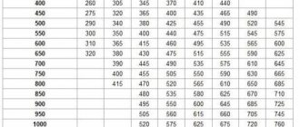
Appendix 4
Table 1
Table for determining air speed
by ball catathermometer
| H/Q ratio | Air speed, m/s | H/Q ratio | Air speed, m/s |
| 0,33 | 0,05 | 0,59 | 0,97 |
| 0,34 | 0,06 | 0,60 | 1.00 |
| 0,35 | 0,08 | 0,61 | 1,03 |
| 0,36 | 0,09 | 0.62 | 1,07 |
| 0,37 | 0,11 | 0,63 | 1.11 |
| 0,38 | 0,12 | 0,64 | 1,15 |
| 0,39 | 0,14 | 0,65 | 1,19 |
| 0,40 | 0,16 | 0,66 | 1,22 |
| 0,41 | 0,18 | 0,67 | 1,27 |
| 0,42 | 0,20 | 0,68 | 1,31 |
| 0,43 | 0.22 | 0.69 | 1,35 |
| 0,44 | 0,25 | 0,70 | 1,39 |
| 0,45 | 0.27 | 0.71 | 1,43 |
| 0,46 | 0.30 | 0,72 | 1,48 |
| 0,47 | 0,33 | 0,73 | 1,52 |
| 0,48 | 0,36 | 0.74 | 1,57 |
| 0,49 | 0,40 | 0,75 | 1,60 |
| 0,50 | 0,44 | 0.76 | 1,65 |
| 0,51 | 0,48 | 0.77 | 1,70 |
| 0,52 | 0,52 | 0,78 | 1,75 |
| 0.53 | 0,57 | 0.79 | 1,79 |
| 0,54 | 0,62 | 0,80 | 1,84 |
| 0,55 | 0,68 | 0,81 | 1.89 |
| 0,56 | 0,73 | 0.82 | 1,94 |
| 0,57 | 0,80 | 0,83 | 1,98 |
| 0,58 | 0,88 | 0,84 | 2,03 |
Rules for determining air speed in an air duct
As the diameter of the pipes increases, the air speed decreases and the pressure drops.
The air flow rate in the ventilation is directly related to the level of vibration and noise in the system. These indicators must be taken into account when calculating behavior. The movement of the air mass creates noise, the intensity of which depends on the number of pipe bends. Resistance also plays a big role: the higher it is, the lower the speed of movement of air masses will be.
Noise Level Standards
Based on sanitary standards, the maximum possible sound pressure levels in the premises are established.
Exceeding the listed parameters is possible only in exceptional cases when it is necessary to connect additional equipment to the system.
Vibration level
The level of noise and vibration depends on the inner surface of the pipe.
During operation of any ventilation device, vibration is produced. Its performance depends on the material from which the air duct is made.
Maximum vibration depends on several indicators:
- the quality of gaskets that are designed to reduce vibration levels;
- pipe manufacturing material;
- duct size;
- air flow speed.
General indicators cannot be higher than those established by sanitary standards.
Air exchange rate
Air masses are purified through air exchange; it is divided into forced and natural. In the second case, it is achieved by opening windows, vents, in the first through the installation of fans and air conditioners.
For an optimal microclimate, air changes should occur at least once an hour. The number of such cycles is called the air exchange rate. It must be determined in order to establish the speed of air movement in the ventilation duct.
The frequency rate is calculated using the formula N=V/W, where N is the frequency rate per hour; V is the volume of air that fills a cubic meter of room per hour; W is the volume of the room in cubic meters.
Calculation Rules
Noise and vibration are closely related to the speed of air masses in the ventilation duct. After all, the flow that passes through the pipes is capable of creating variable pressure that can exceed normal parameters if the number of turns and bends is greater than the optimal values. When the resistance in the channels is high, the air speed is significantly lower, and the efficiency of the fans is higher.
Many factors influence the vibration threshold, for example, pipe material
Standard noise levels
SNiP specifies certain standards that affect residential, public or industrial premises. All standards are indicated in tables. If the accepted standards are increased, it means that the ventilation system is not designed properly. In addition, exceeding the sound pressure norm is permissible, but only for a short time.
How efficiently fans operate depends on the level of vibration. The size of the duct, the quality of the gaskets, and the material from which the pipes are made all affect the vibration threshold.
If the maximum permissible values are exceeded, it means that the channel system was created with some shortcomings that must be corrected in the near future. Fan power can also influence vibration levels exceeded. The maximum air speed in the duct should not contribute to an increase in noise.
Principles of assessment
Various materials are used to make ventilation pipes, the most common of which are plastic and metal pipes. The shapes of air ducts have different sections, ranging from round and rectangular to ellipsoidal. SNiP can only indicate the dimensions of exhaust pipes, but cannot in any way standardize the volume of air masses, since the type and purpose of the premises may differ significantly. The prescribed standards are intended for social facilities - schools, preschool institutions, hospitals, etc.
All dimensions are calculated using certain formulas. There are no specific rules for calculating air speed in air ducts, but there are recommended standards for the necessary calculation, which can be seen in SNiPs. All data is used in the form of tables.
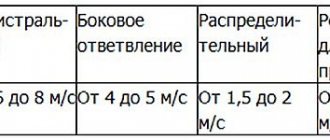
You can supplement the given data in this way: if the hood is natural, then the air speed should not exceed 2 m/s and be less than 0.2 m/s, otherwise the air flow in the room will be poorly renewed. If the ventilation is forced, then the maximum permissible value is 8-11 m/s for main air ducts. If this standard is higher, the pressure in the ventilation will be very high, which will lead to unacceptable vibration and noise.
Algorithm and formulas for calculating air speed
An option for calculating air speed in pipes of different diameters.
Calculation of air flow can be done independently, taking into account the conditions and technical parameters. To calculate, you need to know the volume of the room and the multiplicity rate. For example, for a room of 20 square meters, the minimum value is 6. Using the formula gives 120 m³. This is the volume that must move through the channels within an hour.
The speed in the duct is also calculated based on the cross-section diameter parameters. To do this, use the formula S=πr²=π/4*D², where
- S – cross-sectional area;
- r – radius;
- π – constant 3.14;
- D – diameter.
Once the cross-sectional area and air flow rate are known, its speed can be calculated. To do this, use the formula V=L/3600*S, where:
- V – speed m/s;
- L – flow rate m³/h;
- S – cross-sectional area.
The noise and vibration parameters depend on the speed in the air duct cross-section. If they exceed the permissible standards, you need to reduce the speed by increasing the cross-section. To do this, you can install pipes from a different material or make a curved channel straight.
Air flow calculation
It is important to correctly calculate the cross-sectional area of any shape, both round and rectangular. If the size is inappropriate, it will be impossible to ensure the desired air balance. An air duct that is too large will take up a lot of space. This will reduce the space in the room and cause discomfort to residents. If the calculation is incorrect and a very small channel size is chosen, strong drafts will be observed. This occurs due to a strong increase in air flow pressure.
Sectional calculation
When a round duct changes to a square one, the speed will change.
To calculate the speed at which air will flow through the pipe, you need to determine the cross-sectional area. The following formula is used for calculation: S=L/3600*V, where:
- S – cross-sectional area;
- L – air flow in cubic meters per hour;
- V – speed in meters per second.
For round air ducts, it is necessary to determine the diameter using the formula: D = 1000*√(4*S/π).
If the duct is rectangular rather than round, instead of the diameter, you need to determine its length and width. When installing such an air duct, the approximate cross-section is taken into account. It is calculated by the formula: a*b=S, (a – length, b – width).
There are approved standards according to which the ratio of width to length should not exceed 1:3. It is also recommended to use tables with standard dimensions offered by air duct manufacturers.
Round ducts have an advantage. They are characterized by a lower level of resistance, so during operation of the ventilation system the level of noise and vibration will be minimized.
Calculation algorithm
When designing, adjusting or modifying an existing ventilation system, air duct calculations must be performed. This is necessary in order to correctly determine its parameters, taking into account the optimal performance and noise characteristics under current conditions.
When performing calculations, the results of measuring the flow rate and speed of air movement in the air channel are of great importance.
Air flow is the volume of air mass entering the ventilation system per unit of time. As a rule, this indicator is measured in m³/h.
Movement speed is a value that shows how quickly air moves in the ventilation system. This indicator is measured in m/s.
If these two indicators are known, the area of circular and rectangular sections, as well as the pressure required to overcome local resistance or friction, can be calculated.
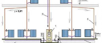
When drawing up a diagram, you need to choose a viewing angle from the façade of the building, which is located at the bottom of the layout. Ducts are shown as solid thick lines
The most commonly used calculation algorithm is:
- Drawing up an axonometric diagram that lists all the elements.
- Based on this scheme, the length of each channel is calculated.
- Air flow is measured.
- The flow rate and pressure in each section of the system are determined.
- Friction losses are calculated.
- Using the required coefficient, the pressure loss when overcoming local resistance is calculated.
When performing calculations on each section of the air distribution network, different results are obtained. All data must be equalized using diaphragms with the branch of the greatest resistance.
Calculation of cross-sectional area and diameter
Correct calculation of the area of round and rectangular sections is very important. An unsuitable cross-section size will not provide the desired air balance.
A duct that is too large will take up a lot of space and reduce the effective area of the room. If the channel size is too small, drafts will appear as the flow pressure increases.
In order to calculate the required cross-sectional area (S), you need to know the values of flow rate and air speed.
The following formula is used for calculations:
S = L/3600*V,
in this case L is the air flow rate (m³/h), and V is its speed (m/s);
Using the following formula, you can calculate the duct diameter (D):
D = 1000*√(4*S/π), where
S – cross-sectional area (m²);
π – 3.14.
If you plan to install rectangular rather than round air ducts, instead of the diameter, determine the required length/width of the air duct.
All obtained values are compared with GOST standards and products that are closest in diameter or cross-sectional area are selected
When choosing such an air duct, the approximate cross-section is taken into account. The principle is used: a*b ≈ S, where a is the length, b is the width, and S is the cross-sectional area.
According to regulations, the ratio of width to length should not be higher than 1:3. You should also use the standard size chart provided by the manufacturer.
The most common sizes of rectangular ducts are: minimum dimensions - 0.1 m x 0.15 m, maximum - 2 m x 2 m. The advantage of round air ducts is that they have less resistance and, accordingly, create less noise during operation.
Calculation of pressure loss due to resistance
As air moves along the line, resistance is created. To overcome it, the fan of the air handling unit creates pressure, which is measured in Pascals (Pa).
Pressure loss can be reduced by increasing the cross-section of the air duct. In this case, approximately the same flow rate in the network can be ensured
In order to select a suitable air handling unit with a fan of the required capacity, it is necessary to calculate the pressure loss to overcome local resistance.
This formula applies:
P=R*L+Ei*V2*Y/2, where
R – specific pressure loss due to friction in a certain section of the air duct;
L – section length (m);
Еi – total local loss coefficient;
V – air speed (m/s);
Y – air density (kg/m3).
R values are determined according to standards. This indicator can also be calculated.
If the duct cross-section is circular, the friction pressure loss (R) is calculated as follows:
R = (X*D/B) * (V*V*Y)/2g, where
X – coefficient. friction resistance;
L – length (m);
D – diameter (m);
V is the air speed (m/s), and Y is its density (kg/m³);
g – 9.8 m/s².
If the cross-section is not round, but rectangular, it is necessary to substitute an alternative diameter into the formula, equal to D = 2AB/(A + B), where A and B are sides.
Material and cross-sectional shape of air ducts
Round ducts are most often used in large enterprises. This is due to the fact that their installation requires many square meters of room space. Rectangular sections are most suitable for residential buildings; they are also used in clinics and kindergartens.
Steel is most often used to make pipes. For a round section it should be elastic and hard, for rectangular ones it should be softer. Pipes can be made of textile and polymer materials.
Choosing the right ventilation pipes
The air duct calculation is done taking into account the size of the room.
Before designing a ventilation system, all indicators of speed, noise and vibration must be taken into account. It is necessary to make calculations taking into account the area of the room to ensure high-quality air exchange. The material of manufacture also plays a big role in the choice.
Galvanized steel air ducts are considered the most universal. They can be operated at high temperatures and pressures. They can be used for any climate zones.
Air ducts made of black steel are most often used in industry. They are heat and fire resistant, but are subject to severe corrosion.
Aluminum corrugated air duct has a high degree of flexibility, strength and elasticity. The material is resistant to high temperatures. But such an air duct has a drawback. Due to the high aerodynamic resistance, there is a lot of noise during operation.
Plastic air ducts are distinguished by their high strength, long service life and ease of installation. They are popular due to their low cost and light weight. The downside is low resistance to high temperatures.
Polyisocyanurate pipes are often installed in residential buildings. They are characterized by high fire safety properties, long service life, and ease of installation.