Published lpunity at 11/12/2018
UUTE - what is it? The easiest way to say it is that this is a set of heat meters that monitor the condition of the building’s heating system. This formulation is quite acceptable, but does not fully explain the concept. UUTE (thermal energy metering unit) is a set of technical means installed on the pipeline to control the parameters of the coolant. The characteristics of liquid moving along highways are regularly measured, recorded and subjected to various calculations.
WHAT'S COOL?
The main thing is that Klimatic is the most inexpensive of the cool ones.
Or the coolest inexpensive one - whatever you like. It is easy to set up - large screen and clear menu.
It can work with wireless temperature sensors (radio communication). Moreover, one outdoor air temperature sensor can be used by several Climatics. This is in case you have several heating circuits.
It has 9 "factory" time programs such as "morning, evening and weekend". This saves a lot of time when setting up.
You can manually switch the Climate control to comfortable or economical mode at any time. And return it back to automatic.
The heating schedule can be adjusted (this is more for specialists).
The climate control system intelligently controls the pump and drive: if heat is not needed, the pump will turn off and the drive will close.
The climate control is always on guard! In any mode, frost protection is provided (if the coolant temperature drops below 10 degrees, the controller will turn on the pump and maintain 10 degrees).
Controls any three-position drives
Adjusting the heating system using pumps
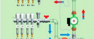
Among the well-known schemes for installing heating systems controlled from a weather-dependent automation unit, the optimal option for regulating the heating temperature of rooms is a scheme using circulation pumps. This scheme is more used for heat supply to district heating buildings, when additional pumps are installed at heating points to pump coolant from the main to a specific consumer. In this scheme, in addition to the pumps themselves, other equally important elements are used, for example, a heat accumulator and a hydraulic separator - a hydraulic arrow.
The essence of this method is to quickly increase the flow rate of coolant to the radiators by switching the pump operation. After receiving information from external and internal sensors, the control unit, according to the program, selects the operating mode of the circulation pump. By increasing or decreasing the coolant supply rate, the automation regulates the flow pumped into the radiators. To achieve the desired temperature, the automation opens, or vice versa, closes the three-way mixing valve and the liquid heated to the desired temperature, under the action of the pump, enters the battery circuit.
This option for controlling the heating system using pumps allows you to bring the room temperature to the desired value in a very short time without adjusting the burner of the heating boiler. It is simple and reliable, and heating boilers do not need to be constantly adjusted, setting the temperature to 40-45 degrees.
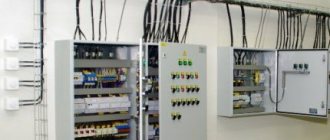
Automatic control unit
Purpose
The heating point contains the main components for controlling the heating system.
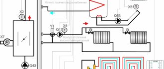
An automatic control unit is an individual heating point designed to control the parameters of the coolant circulating in the heating system, depending on the temperature in the room, outside, in the supply and return pipelines of the circuit.
In addition, the system allows for protection against emergency situations, switching of equipment operating modes, and GSM heating control. In the event of a breakdown or emergency situation, the module is able to notify all subscribers included in the mailing list using SMS messages.
Diagram of the control unit for a two-pipe heating system.
However, this is not a complete list of functions.
The control node can provide:
- Modes and parameters of operation of the heating system circulation pump, set coolant circulation speed;
- Monitoring the maintenance and implementation of the specified temperature schedule of the supply and return pipelines . This allows you to protect the system from overheating and hypothermia;
- Maintaining a given constant pressure difference at the supply and return inputs to the building , which allows all automation to operate normally in normal mode;
- Fine and coarse cleaning of coolant;
- Visual monitoring of all indicators of system operation : temperature in key areas, pressure difference at the inlet and outlet of the unit, specified operating mode, alarm signals;
- Remote heating control by phone and via the Internet;
- Remote control of premises, alarms, entrance doors and gates using additional sensors.
The GSM heating module provides remote communication and control.
Important! To install such a system, the boiler and other equipment must be adapted for electronic control. Old frames with mechanical latches will not work with this scheme.
Device and principle of operation
The photo shows a 3-D model of the control unit.
Any automatic control system includes the following components:
- Sensors and sensors that collect the necessary data in various places in the system;
- Controllers and processors that compare the data received from the sensors with the values dictated by the instruction (program) recorded on the memory card, make a decision and, based on it, issue commands to the execution mechanisms;
- Executing mechanisms that receive commands from controllers and perform simple actions - shut off taps and valves, increase the power of units, switch operating modes of heating equipment, and perform emergency shutdowns of broken components.
Logical diagram of the system operation.
The sensors are pressure and temperature sensors, as well as any additional sensors that allow you to control various processes. The most important are temperature sensors for the supply and return flow of coolant, indoor and outdoor temperature sensors, as well as pressure sensors at the system inlet.
Clip-on temperature sensor.
The role of the controller is played by a low-power computer that reads information from all sensors. A program is recorded on the computer memory card that determines temperature conditions.
The controller compares the received values with the specified ones, and, if necessary, makes a decision to make changes: increasing the coolant supply to one or another circuit, turning off the boiler or switching it to another operating mode, etc.
The controller is assembled without the use of hot cards.
Upon making a decision, the controller sends a control signal to one or another actuator: switching relay, valve or damper servomotor, switch or boiler electronics. Depending on the specified program, the GSM module for heating control can send messages to the owner about a particular event, and after waiting for a response, take certain measures.
Actuator ST 24B.
Heating control in a country house via GSM is carried out using a special module built into the computer.
This module includes the following elements:
- SIM card slot;
- Power supply and battery;
- GSM modem;
- Antenna connector;
- LAN port for connecting to an Internet provider;
- Microprocessor;
- Memory card;
- USB connector for setup and configuration;
- LED indicators or liquid crystal display;
- A contact group with inputs and outputs for collecting data and sending control signals.
Module design with GSM.
Important! Along with the GSM control module, software must be supplied for installation on the mobile phone operating system. The program will help organize remote communication between the controller and operator.
Principle of weather-compensated heating control
Let us explain how room temperature is maintained taking into account changes in outside temperature. When setting up the controller, a so-called temperature curve is established, reflecting the dependence of the temperature of the coolant in the heating circuit on changes in weather conditions outside. This curve is a line, one point of which corresponds to +20°C outside (in this case, the temperature of the coolant in the heating circuit is also +20°C, since it is believed that under such conditions there is no need for heating). The second point is the coolant temperature (say, 70°C), at which even on the coldest day of the heating season the temperature in the room will remain set (for example, 23°C). If the building is not insulated sufficiently, a slightly higher temperature of the coolant in the heating circuit will be required to compensate for heat loss. Accordingly, the slope of the curve will be steep. And vice versa, if everything is in order with the thermal insulation of the house. When making a controller, many similar curves are entered into the device’s memory so that you can then select from the entire family the appropriate line specifically for the conditions of your home.
As a rule, to create the maximum level of thermal comfort, as well as to save fuel, a single street sensor is not enough. Therefore, an additional sensor is often installed inside a heated room. The presence of two sensors at once, both indoor and outdoor, allows you to accurately monitor and quickly adjust the temperature in the premises of the house.
Typically, a room temperature sensor is installed in the so-called reference room - the temperature in it will correspond to your concept of a comfortable thermal background. This room should not be heated by direct sunlight or exposed to drafts. As a rule, children's and bedrooms are chosen as a standard. Installing a room sensor makes it possible to enable the self-adaptation mode, in which the heating curve is selected for the appropriate room automatically - by the microcomputer of the control panel itself. In addition, a room sensor is often integrated into a thermostat, with which you can set the desired temperature and its average level throughout the house. Local temperature control in a single room is achieved by installing thermostatic valves with thermal heads on radiators.
A very important aspect of using a thermostat is, again, fuel economy. Let us explain how it is carried out. Let’s say that guests gathered in the room where the sensor is installed and the temperature increased by 2°C due to the natural heat generation of people. The control panel detects these changes and gives a command to reduce the temperature of the coolant in this circuit, although the street sensor may require just the opposite. Reducing the heat consumption to heat this room naturally saves fuel. But there are also problems here. Flooding the fireplace in the room where the thermostat is set, or leaving a window open for too long, can change the temperature throughout the house. To take into account such factors, many systems provide the possibility of making amendments to the control algorithm by setting the coefficient of influence of the room sensor on the nature of the heating curve. But in general, experts simply do not recommend installing room temperature measuring devices near fireplaces, entrance doors, windows and other sources of heat or cold that can introduce an error in the measurement results.
It should also be noted that installing only a room thermostat, without an outside temperature sensor, significantly increases the inertia of the temperature control system. Changes in the thermal background will occur with a delay, since the automation will begin to operate only when the temperature in the house, for example, drops, and this will happen later than the actual cold snap outside
Modern controllers not only monitor the weather, but also have a fairly large number of functions, some of which are user, and some are service. If the former guard comfort, the latter monitor the condition of the system and ensure the correct and safe operation of the equipment.
Automation of the heating system - what are the problems, is it needed, when to use it
Do you need automation in your heating system, including one that responds to weather changes? Isn't this an unnecessary increase in price? Check out an independent opinion about automation in the heating system. This is not at all what sellers and installers will impose.
Many heating specialists are generally very skeptical about automatic means that control heating depending on the weather.
And there is a reason for it. Read more about what happens in practice with the automation of the heating system, in what cases it is needed, and what exactly is the matter.
How weather-compensating automation works
The principle of operation of automatic means that change the operation of heating depending on the weather is quite simple - if the temperature outside decreases, then the temperature of the coolant increases. And on the contrary, if it gets warmer outside, the temperature of the coolant decreases.
This prevents fluctuations in temperature inside the room - heat losses are compensated ahead of time, without changing the internal microclimate (as planned).
You can adjust settings, change leads and temperature. But it is not always as flexible and wide as we would like. The effectiveness of this system is not always evident. But rather the opposite - automation only causes inconvenience. Why?
How and when does lack of automatic control manifest itself?
There are many modern houses that have a very large internal heat capacity and are well insulated on the outside. Then the heavy walls are almost completely heat accumulators.
Some models of weather-dependent automation cannot effectively adapt to this state of affairs. A situation arises when daily temperature fluctuations are processed very poorly by automation. At least with control you can see that everything is working with a bang.
The temperature drops significantly in the evening - heating begins in accordance with the settings. But the building itself would not have cooled down until the morning - as a result, by morning it was a bit hot. Day comes, the heating turns off, and the house cools down at night so that it becomes chilly.
The automation is not adjusted to heat-intensive houses and, as a result, the temperature inside fluctuates at random. The situation is worse than if it were a simple reaction to the internal temperature of the home.
The situation is significantly aggravated if weather-dependent equipment also controls heated floors - the most heat-inertial system in the house. This is a serious mistake in heating installation.
As a result, owners, having lost faith in the settings, simply turn off the equipment so as not to interfere with their lives. The system operates as usual - based on the temperature of the coolant or air inside.
Thus, often weather-compensated automation can only respond normally to seasonal fluctuations - when the average daily temperature definitely changes.
But isn't it easier to independently adjust the heating according to the season? It won't be difficult.
What are the systems and how do they work?
Wall-mounted automated boilers often have programmed operating options depending on the weather. Then you just need to purchase an external sensor and connect it to the boiler, and the weather-dependent automation is ready. It is simple, inexpensive, accessible, and therefore used everywhere.
But with a floor-standing boiler, weather-dependent automation, although possible, will cost a pretty penny. It is provided with a whole range of additional expensive equipment.
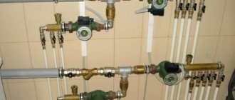
- Two mixing units included.
- Manifold for mounting these units.
- Shut-off valves and fittings for this installation.
- Controller
- Sensor with wires
Together with work and adjustment, all this pleasure reaches up to 2000 USD.
But that is not all. After all, equipment breaks down and needs to be serviced. The more complex the system, the greater the likelihood of failure. And here is electronics, the breakdowns of which cannot be repaired; the unit needs to be replaced. And all this happens in the middle of winter. At the same time, the heating does not work, it is awaiting repair of this equipment....
All this suggests that even for a person who does not want to delve into his boiler room and adjust something there in order to adjust the heating according to the season, such automation is not needed. It is better and safer to delve into the regulation and do it once every two months than to worry in this way.
Also, read more about whether a hydraulic arrow is needed in the heating system. But, nevertheless, the specified equipment is installed. In what cases is weather response equipment installed in the heating system?
When is weather automation used?
- It’s not uncommon for residents to simply love everything automatic. They like to figure it out and make adjustments. In general, the heating system control equipment in this case is, like a large car, an expensive pleasure that can be done in your free time (adjusting heating in the house is a new hobby).
- The second case is very complex heating systems with many circuits. If one boiler (group of boilers) powers several objects - a house, a cottage, a garage, a sauna, a greenhouse... then it is impossible to manage everything manually and you need to install a fully automatic complex. But at such facilities, as a rule, there is a full-time specialist for maintenance, and the owner does not delve into the nuances of heating operation.
- Another option is large heating areas, production workshops, with shifting operating modes, etc... With such volumes, even the slightest saving on heating is a lot of money. Therefore, everything is regulated automatically.
But in the vast majority of cases, an ordinary house up to 400 sq. m. does not require any weather-compensating automation. If residents can independently adjust the boiler when it gets cold (warming) outside, then this equipment loses all meaning.
Nuances of operation and conclusions on the automation of the heating system
The electronic controller in the heating system controls not only weather changes, but also other functions. In particular, the most important is the management of the hot water supply system. When the boiler heats up, the heating turns off - the rule of DHW priority in any system. This is done by an external controller with a floor-standing boiler, or this function is built into automated boilers.
If the equipment is abandoned, then the priority of the boiler must be ensured by some other means. And this can be done by installing a group of relays and other simple equipment in the circuit, which is an order of magnitude cheaper than “fencing off” the automation. Read more - how to connect a boiler to a non-automated boiler
If the issue of boiler operation with a solid fuel boiler is resolved, then you can completely abandon the automation. It remains to draw conclusions. Weather-compensating automation can be built into a wall-mounted boiler. Then you can easily put it into operation by purchasing an additional external temperature sensor - very simple and functional.
But if you have a non-automated boiler, then you don’t need to install a bunch of complex equipment in addition to it - it’s too expensive and ineffective. It is much easier and cheaper to adjust to the weather “manually”. The exception is very large houses and large heated farms, where automation simply cannot be done without.
It’s also interesting to find out how to make heating in a country house easier and cheaper
Weather-compensated heating control
At first glance, everything is logical, but I had a question about the advisability of constantly adjusting the temperature of the coolant in the heating system. There is an opinion that a one-time adjustment of the heating system over a period of time is sufficient in the event of a sudden change in outside air temperature. In this case, adjustment can be made manually using various remote control systems, while avoiding unnecessary “bells and whistles” in engineering systems and thereby simplifying their operation. In order to understand this, let's look at the second function that requires weather-dependent heating control - saving energy resources. I am sure that you don’t have to be an academic to answer the question of what type of coolant supply control will be the most energy efficient. Naturally, it's automatic. But the question immediately arises: by how much are the costs of generating thermal energy reduced if you use weather-dependent heating control, and how reasonable are the costs for it?
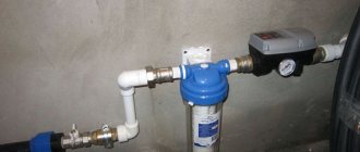
Sensors
The sensors are designed to monitor pressure and temperature indoors, outdoors and coolant in the pipelines of the heating system.
Temperature sensors are:
Submersible . Designed to take readings about water heating in pipes. Their installation is carried out in certain areas of the system. These sensors are bimetallic and alcohol
Remote . This type of sensor is installed outside the heating system. Recently, wireless models have become popular, which transmit information using auxiliary electronics, which makes it possible to install them almost anywhere - in a separate room or outdoors.
Pressure sensors can be mechanical - pressure switches (mechanical measurement of pressure difference and electrical conversion) and analog pressure sensors (conversion of pressure directly into an electrical signal, for example, using piezo elements).
Autonomous heating boilers - non-volatile automation.
Boilers equipped with non-volatile automation are protected from sudden power outages. As a rule, they operate without the use of forced coolant circulation, which means they can work autonomously. Such a heating device is controlled by boiler automation, the operation of which is based on the use of gases that can expand significantly under the influence of temperature.
A special sensor with such gas is installed at the top of the heat exchanger, where the temperature is highest. As the temperature of the coolant increases, it increases in volume and its pressure increases. The sensor, using a copper tube, communicates with the membrane, which, in turn, is mechanically connected to the valve that controls the fuel supply to the burners. With approximately the same type of action, a sensor is installed on Galan electrode boilers.
Using the controls, you can adjust the valve cut-off threshold, and thus control the water temperature in the heating circuit.
Non-volatile automation for boilers is installed, as a rule, in domestically produced parapet heating installations.
Modern control devices are electronic automation systems.
Modern automation devices for wall-mounted boilers operate on a different principle. They use a solenoid valve that is controlled by a microprocessor unit. This is explained by the fact that this control method makes it possible to more accurately regulate the operating mode and is more convenient for the consumer. The boiler is usually equipped with a display and buttons for controlling operating modes. Just a few clicks are enough to set the required mode, and then the smart electronic system itself will maintain optimal operating parameters.
Technically, the electronics in such boilers control a three-way valve and a circulation pump. A three-way valve with an electric drive allows you to switch the flow of coolant to provide hot heating of DHW water or to completely turn off the heating circuit. This is necessary, for example, in the summer when there is no need for heating. If the boiler operates only in the DHW supply mode, and there is no water flow, then the automation stops the circulation pump and turns off the burner.
Main menu
Hello! Thermal energy metering unit is a measuring complex that is designed to control the amount of heat consumed from the main heating network. As a rule, the metering unit is installed in ITP (individual heating points) of apartment buildings and social and cultural buildings, on the pipelines of the heating supply network.
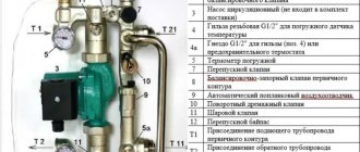
Metering unit device
A typical heat metering unit for an apartment building consists of several parts and units. It is mandatory to install metering units: on the heating inlet pipe (supply) and the heating outlet pipe (return).
Depending on the functional characteristics of the heat consumption of each specific house, there may be more or fewer metering units.
All these nodes are connected into one accounting system using cable routes leading from the devices to one common computer. The computer, located in the instrument cabinet, calculates the amount of heat consumed by recalculating instrument readings.
It can also be equipped with a GPRS transmitter, which, using a cellular network, transmits on request (or on a schedule) the readings of all devices of the organization - the hot water supplier, and, if the transmitter is appropriately configured, to the consumer. Typically, these readings are verified using a transmitter once a day. This form of data transfer is called dispatching. The consumer can independently check the readings at any time by opening the instrument cabinet and looking at the electronic display of the computer.
Let's take a closer look at the device of the metering unit. The heat metering device is installed at the input of the heating network into the building in the ITP.
Two control pressure gauges are installed in front of the flow meters (on the supply and return) of the metering unit and after them (or, at a minimum, fittings for pressure gauges must be installed). Next, after the inlet pressure gauge, there is a device - a flow meter. It is designed to take into account the amount of water that passes through a given pipe.
A temperature sensor is installed after the flow meter. Typically, the electronic sensor is not equipped with a control panel or an analogue temperature indicator arrow, so another control thermometer is installed next to it, which can be used to check the temperature visually.
In principle, these are all devices that are involved in measuring water consumption. Cable routes go from the flow meter and temperature sensor to the computer, which, knowing the amount of water consumed and its temperature, will calculate the amount of heat consumed in gigacalories. It is advisable to install the temperature sensor after the flow meter.
All pipeline fittings that are designed to discharge water or take it into non-residential buildings for utility premises must be located after the metering station. No bypasses, tie-ins or other systems that allow water to be taken bypassing the metering unit are allowed. For example, after the metering unit, a drain valve and a safety valve are usually installed. In case of dangerous excess pressure, the safety valve is activated and excess water is discharged into the sewer.
Calculator operation
Readings from all individual metering units are transmitted to the computer. As already mentioned, for each individual metering unit, the amount of heat passing through each pipe is calculated by checking the temperature of the water that flows through it from the temperature sensor, and the readings of the flow meter, which counts the amount of water passing at each moment of time.
For a two-wire heating system, which is most common, the amount of heat consumed is determined by the difference in the readings of the input and output pipes. In this case, the computer determines the amount of heat received through the input pipe and subtracts from it the amount of heat transferred back to the central heating network through the output pipe. As you can see, there is no need to overpay for the amount of thermal energy that is sent back to the central network.
For example, in the cold season, when more heat is required to heat the premises, the amount of heat consumed from the central heating network will be greater. Accordingly, the difference between the temperature of the inlet and outlet pipes increases, and this is all taken into account by the calculator when calculating the amount of heat consumed. In warm weather, on the contrary, the difference between the temperature of the inlet and outlet pipes is smaller, and, accordingly, the calculator will calculate a smaller amount of heat consumption.
The procedure for servicing the thermal energy metering unit. Access and security
It is definitely necessary that metering units are serviced by people who have special education and have undergone the necessary training. To service such a unit, it is desirable not only to have an instrument mechanic at the vocational school level. It is best to conclude an agreement for the maintenance of heat energy metering units with a specialized organization. Typically, the management company or homeowners association does this and enters into an agreement for servicing the metering unit with a specialized company. Sometimes the services for installation, adjustment and maintenance of the metering unit are undertaken by the organization - the hot water supplier.
The metering unit is an economically important element in calculating heat consumption in housing and communal services. Therefore, all work to control it must be carried out with the knowledge of the organization supplying the coolant to the house in order to prevent abuse and basic theft.
Devices must have the necessary seals. First of all, the calculator is sealed. Seals are also placed on all fitting connections between the elements of the metering unit. Seals are also placed on temperature sensors and on the flow meter.
Automation equipment for boiler rooms
Automation technical means:
- sensors of technological process parameters;
- actuators that move regulatory bodies according to commands in the desired direction;
- control equipment that processes information from sensors in accordance with the algorithms and programs embedded in it and generates commands for actuators;
- devices for selecting control modes and for remote control of actuators;
- means of displaying and presenting information to operational personnel;
- devices for documenting and archiving technological information;
- means of collective presentation of information.
All this technology has undergone revolutionary changes over the second half of the last century, not least thanks to the achievements of Soviet science. For example, pressure gauge instruments, widely used in measuring pressure, flow, speed and level of liquids and gases, as well as in measuring force and mass, have changed the physical principle of the sensing element.
Instead of a membrane that bends under the influence of force and moves the rod of an electromechanical transducer, they began to use a strain gauge method. Its essence is that some materials, when subjected to mechanical action, change their electrical parameters. A sensitive measuring circuit detects these changes, and a computing device built into the device converts them into a process parameter value.
Boiler automation diagram
Devices have become more compact, more reliable, and more accurate. And more technologically advanced in production. Modern actuators don't just accept "on" and "off" commands, as they did for many years. They can accept commands in digital code, independently decipher them, execute them and report on their actions and their condition. Control technology has evolved from tube regulators and relay-contact circuits to microprocessor-based control, logic and demonstration controllers.
Abroad, the use of such controllers in automation systems for various objects began a little earlier. A microprocessor controller is a computing device designed specifically to control a technological object located in its immediate vicinity.
The controller consists of the following blocks and devices:
- power unit;
- calculator;
- block for input of analog signals of different ratings with galvanic separation;
- device for inputting discrete active (in the form of voltage) and passive (in the form of a dry contact) signals;
- block for outputting analog signals of different ratings with galvanic separation;
- device for outputting discrete active and passive signals;
- an interface communication device for connecting the controller to the system information field.
Signal input and output blocks - blocks of the ICD group (communication devices with the object) - are all multi-channel, have from 8 to 16 channels. The controller is assembled for a specific task using the design layout method. The composition and number of USO blocks is selected based on the number of corresponding signals in the system. The computer block contains a processor, random access memory (RAM) and read-only memory (ROM). A library of algorithms is stored in ROM. Its composition covers almost all control tasks used in such systems - regulation, arithmetic calculations, dynamic transformations, logical actions.
Home automation
Programming of controllers is carried out using the technological programming method. For modern controller models, this method is an assembly of a functional diagram of a control task on the monitor screen.
After a simple check for errors, the program circuit is loaded into the controller’s RAM. The intuitive accessibility of the method for traditional machine gunners contributed to the rapid and widespread spread of RemiKonts.
Algorithms and characteristics of controllers
For heating points, MZTA offers a library of algorithms. If it does not contain suitable algorithms, you can develop them yourself. The development of algorithms is carried out in a special CONGRAF environment, and then, using the CONSOLE software tool, they are loaded into a programmable controller.
TYPICAL PROJECTS for automation of heating points
A typical heating substation control loop based on a programmable controller usually includes the following functional controls:
- sensors (recommended for typical projects are indicated in brackets): temperature (immersion temperature sensor, Pt1000, 200 mm, Regeltechnik, TF65T),
- pressure (DanfossMBS 1700, MBS 3000),
- unauthorized access, optional (IO-102-14 (SMK-14, reed switch) magnetic contact security detector, Komplektstroyservis);
- low-power (valve actuators, recommended DanfossEV210A, EV220A, EV310A, EV210B, EV220B, etc.);
The feasibility of using a programmable controller, the need to supplement it with expansion modules or the configuration of Master/Slave programmable controllers, depends on:
- functional control elements used in the technical solution;
- characteristics of the heating object: heated area,
- number of storeys,
- spatial configuration of the location of pipelines and radiators in the heating system of the facility;
- the presence of special zones with special thermal conditions.
Table 1 shows the outputs of programmable controllers, and Table 2 shows the outputs of expansion modules, which are used as automation for heating points to control actuators in the control loop.
Table 1. Outputs of programmable controllers for heating points and units
| Programmable controller | Output type | Qty | Galvanic isolation from controller circuits | Limit load characteristics |
| MC8 | Discrete, “Electronic key” (open collector – MC8-301), | 8 | No | 24V (48V – max), 0.15 A (DC) |
| Discrete, “Electronic key” (optocoupler triac - MS8-302) | 8 | Eat | ~24V (48V – max), 0.8 A (AC) | |
| Analog: — Current source — Voltage source | 2 | No | 0 A – 0.02 A 0 V – 10 V | |
| RS485 port | 1 | Eat | Modbus RTU protocol | |
| MC12 | Dry contact (relay) | 8 | Eat | Up to ~250 V Up to 3A AC current |
| Analog: — Current source — Voltage source | 4 | No | 0 A – 0.02 A 0 V – 10 V | |
| RS485 port | 1 | Eat | Modbus RTU protocol | |
| MC6 | Dry contact (relay) | 3 | Eat | Up to ~250 V Up to 3A AC current |
| Discrete, “Electronic key” (optocoupler triac) | 2 | Eat | Up to ~ 380 V, 0.8 A AC current | |
| Analog: — Current source — Voltage source | 5 | No | 0 A – 0.02 A 0 V – 10 V | |
| ML9 | Discrete, “Electronic key” (open collector) | 6 | No | PWM, 24V (48V – max), from 0.01 A to 10A (DC) |
| 2 | No | 24V (48V – max), from 0.01 A to 10A (DC), | ||
| MA8 | “Electronic key” (optocoupler triac) | 2 | Eat | 24V(36V – max), 0.1 A (AC) |
| Analog: — Current source — Voltage source | 2 | No | 0 A – 0.02 A 0 V – 10 V |
Table 2. Outputs of programmable controller expansion modules
| Expansion module | Output type | Qty | Galvanic isolation from controller circuits | Limit load characteristics |
| МR20 | Discrete, “Electronic key” (open collector) | 20 | Eat | 24V (48V – max), 0.5A (DC) |
| MA8 | Discrete, “Electronic key” (optocoupler triac) | 2 | Up to ~36 V - max 0.1A | |
| Analog: — Current source — Voltage source | 2 | No | 0 A – 0.02 A 0 V – 10 V | |
| МR8 | Dry contact (relay) | 2 /4* | Eat | Up to ~250 V Up to 3A AC current |
| ME16 | 4 | Up to ~250 V Up to 3A AC current |
*depending on version
All outputs of programmable controllers, as well as expansion modules, are equipped with built-in spark-extinguishing circuits. This reduces the risk of failure of the output circuits of the controllers in cases, and also reduces induced noise in the controller if there are no spark-extinguishing circuits in the connected circuit with a reactive load, for example, in the relay winding circuit.
Additional components of spark arresting circuits intended for installation on the connected load are included in the installation kit of the supplied Kontar programmable controllers.
Depending on the features of a particular solution, control signals to actuators can be supplied through:
- analog output 0 V – 10 V;
- discrete output: connected directly to the actuator;
- connected to a power switch, which in turn controls the power device;
Control influences of automation of thermal units, which can be used when creating control algorithms:
- Defined in the real-time scheduler (built into the programmable controller)
- Manual control signals (built-in or plug-in toggle switches, buttons)
- Sensor signals are logical (presence sensor, temperature sensor)
- Sensor signals are analog (temperature, pressure)
- Command from the control center
- Command from the Master controller
Ports and inputs of programmable controllers that can be involved in control algorithms for a heating substation are shown in Table 3, similar ports and inputs of expansion modules are shown in Table 4. The configuration of the ports of programmable controllers is determined by the WebLinker interface submodules installed on them.
Table 3. Ports and inputs of programmable controllers
| Ports/Inputs | Programmable controller | ||||||
| MC8 MS12 | MS6 | ML9 | |||||
| Number of places for connecting submodules | 1 | ||||||
| WebLinker EM submodule ports | Ethernet + RS232 | ||||||
| WebLinker USB Submodule Ports | Ethernet + USB | ||||||
| WebLinker Modem submodule ports | RS232, allows you to connect a modem | ||||||
| RS485 port for intra-system communication via KontarBus protocol, number of ports (there is galvanic isolation from the controller circuits) | 1 | ||||||
| RS485 port for interaction with peripheral devices , both via the standard Modbus RTU protocol and using manufacturers’ own protocols (there is galvanic isolation from the controller circuits) | 1 | ||||||
| Universal analog input: Limit maximum value of the measured parameter at the universal analog input for: | |||||||
| - active sensors, with an output signal in the form of direct current | up to 50 mA | ||||||
| - active sensors, with an output signal in the form of constant voltage | up to 10V | ||||||
| — passive temperature sensors with internal resistance | 50 Ohm ÷ 10 kOhm; | ||||||
| /number of inputs | 8 | 8 | 5 | — | |||
| Analog input for connecting sensors with constant voltage input signal 0 ÷ 10 V, no. | — | — | — | 2 | |||
| Analog input for connecting sensors with internal resistance 50 ÷ 1000 Ohm , count | — | — | — | 3 | |||
| Discrete input (optoelectronic pair) / number of inputs / (There is galvanic isolation from the controller circuits) | 4 | ||||||
| *Manual switch (Push button) | 4 | — | |||||
*When the controller is equipped with a built-in (MD8.102) or external (MD8.3) control panel.
Table 4 Ports and inputs of programmable controller expansion modules.
| Expansion module | Input type | Qty | Limit load characteristics |
| ME20 | Discrete, in the form of: “dry contact” (relay contact), electronic key (open transistor, triac); (There is galvanic isolation from the controller circuits) | 20 | 0; ~220 V. (for ME20M.3, configurable) |
| 24V (36V – max), 10 mA (DC) | |||
| ME16 | 16 | ||
| МR8 | 8 | ||
| MA8 | 4 |
The discrete inputs of programmable controllers and expansion modules are designed to connect to them sensors with discrete outputs in the form of a key (relay, open collector, optocoupler triac, etc.). This solution makes it possible to simplify the coordination of programmer inputs with most types of sensors that transmit information about the measured parameter in discrete form.
The binary inputs are galvanically separated from the controller/expansion module circuits.
The measuring function embedded in programmable controllers and expansion modules allows you to measure an analog signal depending on the type of sensor/single:
| by voltage | – 0,1% – 0,2% |
| by current | – 0,1% – 0,3% |
| by resistance | – 0,3% |
| by temperature (for temperature sensors) | – 0.5°С – 1.0°С |
To correctly connect the sensor to the analog input of a programmable controller or expansion module, a configurator is provided at each input in the form of a contact group on which jumpers are installed. The configurator is located under the cover of the device housing. The locations and number of jumpers to be installed are determined by the type of sensor and its electrical characteristics. Jumpers are included in the delivery package.
Depending on the scale of the task of automating the control of a heating point, the following can be implemented:
- Local control of a heating point in configurations: autonomous controller;
- controller network: Master - Slave.
- single controller;
An autonomous controller can be implemented on the basis of any programmable controller, and if the algorithm is simple enough, then on the basis of ME16 and MR8 expansion modules capable of performing the functions of programmable relays.
The Master or Slave roles in the configuration can be performed by programmable controllers.
To organize stationary local control of a heating point, special control panels equipped with indicators, control buttons and a liquid crystal display can be used:
- MD8.102 – built-in, installed on the housing of the MC8/MC12 programmable controller;
- MD8.3 – remote, usually installed on the door of the automation cabinet.
MD8.1-01 Control panel for controller MC6.1, with housing cover, display, 4 buttons, 8 LEDs Price 9`100 rub.
Buy in the MZTA online store
MD8.3External control panel. Price 20`300 rub.
Buy in the MZTA online store
The most convenient organization of local control of a heating point can be implemented on the basis of an external operator console. We recommend external WEINTEK touch screen controls for installation.
If adjustments to algorithms are rarely made, and there are few maintenance specialists, then the use of external control panels can be completely abandoned. Their role can be played by a portable laptop, tablet or smartphone connected to the controller directly at the location of the heating point via an access point or via a wired interface (USB, Ethernet, RS232). To provide this capability, there are special submodules.
WeintekTouch operator consoles Price from on request
Buy in the MZTA online store
Dispatch of thermal energy metering units or remote access to a facility can be organized both on the basis of wired solutions (Ethernet, Internet) and on the basis of wireless radio communication technologies, for example, via a GSM modem.
Programmable controllers, in accordance with a given list of critical parameters and events, transmit the corresponding data to the dispatch system and/or store them in their internal memory.
KontarBus protocol used for intra-system communication, incl. and with a web server, is encrypted and is a reliable means of protecting the automation control system from unauthorized access.
Disadvantages of weather-sensitive automation
Here, oddly enough, there are much more significant positions
- Price if we are talking about a floor-standing boiler.
- The main disadvantage of external weather-compensating automation that is not built into the boiler is the difficulty of maintenance. Often, people call repairmen without even knowing the model of their controller. There are a lot of controllers, so they don’t carry them with them, except in cases where they know exactly for what purpose and model of boiler they are going. The controller cannot be repaired on site. You have to pull out the wires that are connected to the controller and connect them directly. This is the worst case scenario. At best, they take the controller away, check it, and buy a new one. The result is unnecessary spending and worry. In contrast to the lack of weather-compensated automation. As a rule, nothing breaks there due to regular maintenance.
- With automation, which is connected to a large number of electronic devices, there are problems and it is impossible to eliminate them, you just need to change them.
Installation Features
Weather-compensated automation has a number of installation features. The main ones are the choice of installation location for the external and internal temperature sensor.
The external sensor is mounted so that it is protected from direct sunlight. It should also not be blocked from the wind by any building structures. Most often, the north-eastern side of the building is chosen, at a height of approximately a meter and a half from the ground. The sensor must be removed from the wall of the house so that heat loss does not affect its readings.
The internal sensor is installed in the so-called reference room. It should have the average temperature in the house, and its fluctuations should be minimal. There should not be many people in the room; it is not advisable to use the fireplace. It should not be in direct sunlight or near the front door. A bedroom or children's room is best suited for these conditions.
The indoor sensor must be mounted in a reference room
If in private houses the system directly controls the boiler power, then in large apartment or public buildings the system controls the operation of the return valve, which releases a larger or smaller part of the waste coolant back into the heating circuit.
Operating principle
When setting up the controller, a “curve” is specified. With its help, the program calculates the need to heat the room. The initial position of the curve is the point at which the temperatures of the coolant and the environment are equal. Typically this is 20 degrees Celsius. After calibration, the device independently monitors the need for temperature changes.
Manufacturers specify several curves in the PA so that setup does not take extra time. Having selected the program, the specialist starts the system. Further, it functions independently.
For better synchronization, it is necessary to install two sensors - one outside, the second inside.
By checking the readings, the system will not produce additional heating at a comfortable room temperature.
For this reason, it is necessary to correctly select the room in which the sensor will be installed.
Warming up or cooling the coolant takes time, so the heating cannot adapt sharply to temperature changes.
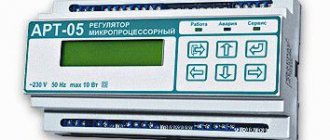
Controller
The controller is the core of the hardware device. It monitors sensor readings and sets the room temperature. The factory functions of the device are responsible for heating, and also inform the owner about problems. Custom settings are designed to maintain maximum comfort.
ACU dispatching
Additionally, it is possible to organize cabinet dispatch using the OwenCloud cloud service. OwenCloud is a cloud service from the OWEN company, used for remote monitoring, management and storage of data archives for OWEN devices used in automation systems. The service is accessed using a web browser or mobile application via the Internet.
The service provides users with the following basic functionality:
- Collect data from connected devices.
- Storage of read data for 90 days.
- Display data in the form of graphs and tables.
- Displaying devices on the map.
- Remote device management.
- Emergency notifications via email and Telegram, push notifications for the mobile application.
- Integration with SCADA systems using the free ARIES OPC server.
- Open API for integration with other software.
The basic functionality of the OwenCloud service is provided free of charge.
To integrate OwenCloud into the ACU, the OWEN PM210 GSM modem was installed.
WEATHER DEPENDENT - HOW IS IT?
Heating system designers design systems for the coldest days of the year (the coldest five-day period). And it is on these days that the boiler must produce the calculated coolant temperature - as a rule, the maximum it is capable of. If we maintain this temperature all year, we will overheat the premises. What should I do?
It is necessary to somehow change the boiler temperature. Scientists have long carried out observations and found that the best solution is to measure the air temperature “overboard” and change the temperature “in the supply” according to the “heating schedule”.
Observations were carried out on a variety of buildings, and it turned out that the graph is almost the same for any building, be it stone or frame. And this graph depends only on the difference in air temperatures inside and outside - this difference is also called temperature pressure.
What automatic settings are there?
Currently, the market offers consumers a wide selection of control devices. Therefore, you need to know what automation systems for home heating systems generally exist, and what to give preference to.
Room thermostat
According to installation criteria, there are:
- Wired thermostats. The advantage of this type is the ability to supply power up to approximately 50 meters via wires.
- Wireless thermostats. The advantage is that it is not necessary to create holes for the wires. However, they have a significant drawback - reinforced concrete walls reduce the signal power.
According to functionality they are distinguished:
- Simple thermostats. They retain the desired level of warmth.
- Programmable thermostats. Such devices are capable of setting a certain number of degrees for a whole week in advance (the period depends on the model) with maximum accuracy down to seconds. The advantages also include cost savings due to weekly programming.
Thermostats are also distinguished:
- Electronic thermostats. The kit contains three components: temperature sensor, signal transmitter, relay. The main advantage of the device is the maximum accuracy of the equipment. Don't forget ease of use.
- Mechanical thermostats. The basis of the devices is the ability to change properties under the influence of temperature levels. Due to temperature changes in the gas membrane, a circuit is closed or opened, causing certain mechanisms to work.
- Electromechanical thermostats. The mechanism of the device is much simpler than an electronic one. The main element is the relay. The node looks like a tube, which is filled with a special substance that reacts to temperature. If the boiler heats up, the substance expands; similarly, when the boiler cools, the substance contracts. And the drive, dependent on the substance, regulates the temperature thanks to an electrical circuit.
Connection can be made to:
- Kotlu;
- To the pump;
- Servo drive;
Thermal head
This is a thermostatic element that, under the influence of the external environment, slightly opens or closes the radiator. An inexpensive type of automation for heating a home. A significant advantage is that the thermal head is very convenient for local heating, and there are also significant cost savings. Of the minuses: firstly, the adjustment occurs according to standards consisting of abstract numbers, not degrees. Secondly, the sensor measures the degree of heat around the installation, but not the room, which reduces the accuracy of the device.
Weather-compensated automation
The design of weather-dependent automation for heating a house is simple: as the weather outside decreases, the temperature of the coolant increases. However, a weather-dependent installation has a very significant drawback - the system sometimes does not have time to adapt to the temperature, and, therefore, the effect is delayed. The especially mentioned disadvantage manifests itself if an addition is connected - heated floors. The disadvantages include the fact that the devices do not operate entirely correctly, approximately, so the change is noticeable only during seasonal climate changes. It is worth noting that the prices for the unit are relatively high. But the units will be very convenient in production, large-scale houses (over 500 square meters).