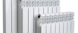
Elevator unit of the heating system: dimensions
There are several categories of these devices; as a rule, they are designated by numbers. The category depends on the diameter of the elevator neck, its dimensions and the diameter of the nozzle.
| Number | Coolant flow | Neck diameter | Weight | Dimensions | |||||
| L | l1 | l2 | h | Flange 1 | Flange 2 | ||||
| 0.1-0.4 t/hour | 10mm | 6.4kg | 256mm | 85mm | 81mm | 140mm | 25mm | 32mm | |
| 1 | 0.5-1 t/hour | 15mm | 8.1kg | 425mm | 110mm | 90mm | 110mm | 40mm | 50mm |
| 2 | 1-2 t/hour | 20mm | 8.1kg | 425mm | 100mm | 90mm | 110mm | 40mm | 50mm |
| 3 | 1-3 t/hour | 25mm | 12.5kg | 625mm | 145mm | 135mm | 155mm | 50mm | 80mm |
| 4 | 3-5 t/hour | 30mm | 12.5kg | 625mm | 135mm | 135mm | 155mm | 50mm | 80mm |
| 5 | 5-10 t/hour | 35mm | 13kg | 625mm | 125mm | 135mm | 155mm | 50mm | 80mm |
| 6 | 10-15 t/hour | 47mm | 18kg | 720mm | 175mm | 180mm | 175mm | 80mm | 100mm |
| 7 | 15-25 t/hour | 59mm | 18.5kg | 720mm | 155mm | 180mm | 175mm | 80mm | 100mm |
Other options for thermal units
Improved mixing unit
Based on the basic principle of operation of the elevator unit of the heating system, alternative methods have been developed to maintain the desired temperature level in the pipes for users. Their difference from the traditional scheme lies in the presence of a complex electronic control system.
The first thing the developers of this unit paid attention to was the optimal flow of hot water. Therefore, a thermal energy meter must be installed at the inlet pipe
It makes it possible not only to see the volume of coolant entering the home system, but can also automatically calculate its cost and transmit the data to the management company.
The installed pumps allow you to control the speed of passage of the coolant through the pipes. This is necessary to reduce the error when mixing fluid flows in the nozzle. To do this, temperature sensors are mounted on the inlet and return pipes. If the water heating level is less than the set one, the return pump stops working. To increase the volume of hot coolant, the corresponding pumping equipment is activated.
- Dependency on power supply. The emergency source of electricity can only work for a short time. To protect against voltage surges, it is necessary to install a condensing rectifier;
- As the complexity of a system increases, the likelihood of system failure increases. It is enough for one of the sensors to fail - the optimal mixing parameters will change.
Despite these factors, the popularity of new systems is associated with their ease of use and significant savings on heating costs. This is why improved elevator units for central heating systems will be in demand.
As for the initial costs for the purchase of equipment and installation, these investments are returned in the form of savings on heating costs within 3-5 years. But provided that the design and installation are carried out by professional and honest companies.
An example of integrating an elevator heating unit in conjunction with a heat meter:
Adjustable elevator VARS, AVARS
The VARS and AVARS devices differ from elevators of the above types in that a regulating actuator mechanism (RIM) is installed on a commercially produced unregulated elevator (Fig. 1 and 2). The RIM design ensures high reliability of the heating system operation both with manual (VARS) and automatic (AVARS) regulation. It is simple in design, does not require metal, and is reliable in operation. The design of the RIM ensures high stability of the heating system even at low flow rates of network water.
| Fig.2 This is how VARS works with manual temperature control of the heating system |
More than 1,800 VARS and AVARS devices were installed and operated from 2000 to 2015. in 86 cities of Russia. The simplicity and reliability of the design ensures their long and trouble-free operation. There have been no complaints from any organization regarding their low energy efficiency or failure.
Reviews of the work of VARS and AVARS confirm their economic efficiency ranging from 10 to 45% of the costs before upgrading the heating system.
The cost of installing VARS/AVARS pays off in 2 months/one heating season, and then brings net profit to its owners for many years.
Installing VARS and AVARS instead of an unregulated elevator allows you to reconstruct the transformer substations with a minimum of time and money all year round.
We have a GOST R Certificate of Conformity, catalog sheets and technical specifications for the equipment we produce.
Installation features and testing
Installation of the elevator unit
It is worth immediately noting that installation and testing of the operation of the elevator unit and heating system is the prerogative of representatives of the service company. Residents of the house are strictly prohibited from doing this. However, knowledge of the layout of the elevator units of the central heating system is recommended.
When designing and installing, the characteristics of the incoming coolant are taken into account
The branching of the network in the house, the number of heating devices and the operating temperature are also taken into account. Any automatic elevator unit for heating consists of two parts
- Adjusting the intensity of the flow of incoming hot water, as well as measuring its technical indicators - temperature and pressure;
- Directly the mixing unit itself.
The main characteristic is the mixing coefficient. This is the ratio of the volumes of hot and cold water. This parameter is the result of precise calculations. It cannot be a constant, since it depends on external factors. The installation must be carried out strictly according to the diagram of the elevator unit of the heating system. After this, fine tuning is done. To reduce errors, a maximum load is recommended. This way the water temperature in the return pipe will be minimal. This is a prerequisite for precise control of the automatic valve.
After a certain period of time, scheduled checks of the operation of the elevator unit and the heating system as a whole are necessary. The exact procedure depends on the specific scheme. However, you can draw up a general plan that includes the following mandatory procedures:
- Checking the integrity of pipes, shut-off valves and devices, as well as compliance of their parameters with passport data;
- Adjustment of temperature and pressure sensors;
- Determination of pressure loss during coolant passage through the nozzle;
- Calculation of the displacement coefficient. Even for the most accurate heating scheme for an elevator unit, equipment and pipelines wear out over time. This amendment must be taken into account when setting up.
After this work has been completed, the automatic central heating elevator unit must be sealed to prevent tampering.
You cannot use homemade schemes of elevator units for central heating systems. They often do not take into account the most important characteristics, which can not only reduce operational efficiency, but also cause an emergency.
Elevator unit of the heating system - operating principle
Dependent circuit with two-way valve and pumps in the supply line
Such situations will be avoided by installing metering devices.
At the same time, consumers withdraw water from the circuit as needed. May consist of one or more blocks. Project documents containing all the necessary approvals. Deyneko Individual heating point IHP is the most important component of heat supply systems for buildings. Often, heat from the domestic hot water system is used by consumers for partial heating of premises, for example bathrooms in multi-apartment residential buildings. Cooled network water enters the heating system.
But any system also has disadvantages, the collector unit is no exception: Separate calculations are required for each element of the elevator. Schematic diagram of the ITP for two heating systems with dependent connection to the heating network and a hot water supply system with direct water supply. Changing the lumen changes the speed of water movement. The essence of the heat supply scheme for Moscow
How does an elevator unit work?
Before understanding the structure of the elevator unit, we note that this mechanism is intended to connect end-users of heat to heating networks. By design, the thermal elevator unit is a kind of pump that is included in the heating system along with shut-off elements and pressure meters.
The elevator heating unit performs several functions. First of all, it redistributes the pressure inside the heating system so that water is supplied to the end consumers in the radiators at the specified temperature. When passing through pipelines from the boiler room to apartments, the amount of coolant in the circuit almost doubles. This is only possible if there is a supply of water in a separate sealed container.
As a rule, coolant is supplied from the boiler room, the temperature of which reaches 105-150 ℃. Such high rates are unacceptable for domestic purposes from a safety point of view. According to regulatory documents, the maximum water temperature in the circuit cannot exceed 95 ℃.
It is noteworthy that SanPin currently sets the coolant temperature standard within 60 ℃. However, in order to save resources, a proposal to reduce this standard to 50 ℃ is being actively discussed. According to an expert opinion, the difference will not be noticeable to the consumer, and in order to disinfect the coolant, it will need to be heated to 70 ℃ every day. However, these changes to SanPin have not yet been adopted, since there is no clear opinion about the rationality and effectiveness of such a decision.
The diagram of the elevator heating unit allows you to bring the temperature of the coolant in the system to standard values.
This node allows you to avoid the following consequences:
Batteries that are too hot can cause skin burns if handled carelessly; not all heating pipes are designed for prolonged exposure to high temperatures under pressure - such extreme conditions can lead to premature failure; if the wiring is made of metal-plastic or polypropylene pipes, it is not designed for the circulation of hot coolant.
Elevator unit of the heating system: what is it?
Three modes of operation of main heating networks are measured in degrees, they look like this:
- 95/70.
- 130/70.
- 150/70.
The first value refers to the supply temperature, and the second corresponding to the return pipe. Since the distance to boiler rooms is often quite large, energy loss occurs, forcing adjustments to the numbers taking into account the weather outside the window. These three options have been designed to save fuel consumption.
Purpose of the elevator unit
This important element in the system is designed to reduce pressure and normalize the temperature of the coolant. The process occurs by adding colder water from the heating circuit to the pipeline.
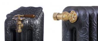
According to generally accepted sanitary standards, the liquid in radiators should not exceed 95 degrees; I will give a few obvious facts regarding this point:
- Extremely heated appliances in the apartment can harm a child after touching them.
- In this situation, cast iron radiators will become vulnerable to mechanical damage and fragile; aluminum radiators can fail.
- Plastic pipes used in room wiring are not designed to withstand very high temperatures and may lose their aesthetic appearance.
To prevent such excesses, an elevator is installed in the heating main; in apartment buildings it is impossible to do without such a part.
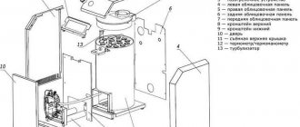
Device
Externally, this element looks like a kind of metal or cast iron structure with three holes, each of which has flanges for connecting the unit to the system. You should find out more about what the elevator unit consists of. The internal structure aroused much greater interest in me, initially I need to disassemble the components separately, it looks like this:
- Frame.
- Nozzle.
- Mixing chamber.
- Innings.
- Return line.
- Logout.
At the supply you can find the highest pressure, at the exit from the diffuser it is lower, and in the return system it is minimal; the same thing happens with the temperature of the liquid. The jumper, which is in a vertical position, cuts into the body at 90 degrees.
Schematic diagram of the elevator unit
A heating elevator will not be able to function productively without proper piping, although the device is quite simple and looks like a pump that supplies liquid under a certain pressure, but there are some nuances in this matter, I will analyze it more precisely.
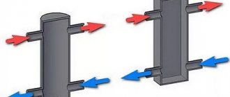
The maximum heated water enters the inlet pipe and moves forward due to pressure. Thanks to the nozzle, an injection effect is created, which forces the liquid entering the receiving chamber to create a vacuum zone.
As the pressure decreases, water is sucked in from the pipe, which, in turn, is connected to the return pipeline. Due to these manipulations, the coolant enters the neck of the elevator and mixing of hot and cold flow begins.
Water, normalized taking into account all safety standards, is returned to the system through a diffuser and distributed to radiators located in apartments; this is what the diagram of an elevator heating unit looks like.
The principle of operation of the unit in the heating system
I believe that the operating principle of a heating elevator can be compared to a water pump, which operates without any external resources.
The design is quite simple and inexpensive, which is why most heating units use this element in multi-apartment building systems. But each unit must be operated properly; without certain conditions, interruptions in operation cannot be avoided.
The heating elevator has three holes with flanges for fastening, one of which is connected to the supply pipeline, the second is responsible for supplying liquid to the radiators, and the third receives the return flow. For proper operation of the network, it is necessary that the pressure difference between the supply and return flow exceed the hydraulic resistance of the heating system.
Elevator with automatic adjustment
I do not consider this type of device to be the most practical due to its dependence on external factors, but the device is quite modern and deserves attention. The design involves changing the nozzle cross-section through automatic adjustment.
How the elevator unit works is that it is connected to a mechanism specially designed for this process, which is located inside the elevator body. It is this component that is responsible for moving the throttle needle back and forth, depending on the temperature of the liquid in the system.
The moving element in the nozzle affects the clearance, as a result of which the coolant supply and its flow rate change. Changes in fluid permeability not only regulate the temperature in the pipes, but also the speed of movement of water in the heating system. This is due to a change in the coefficient when mixing cold and hot flow. I told you how the heating elevator circuit changes the temperature in the main pipe.
An equally important factor is that using an irreplaceable element, you can also regulate the pressure in the pipes and radiators of apartments.
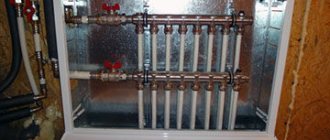
The device directs the flow, creating changes in the coolant in the heating circuit. The design of the device involves the circulation of liquid, so it often comes with such successful additions as distribution units. In apartment buildings, such devices are necessary only because several consumers live in them.
A collector or comb is responsible for the distribution of water; after entering this container, the coolant from the automatic elevator unit goes through the residents’ rooms through many exits. Such manipulation does not affect the pressure in the system; it remains the same.
Scheme development
At the initial stage, heating engineers work on the development of a heating scheme, carry out a series of calculations and achieve the same efficiency indicators of the heating system on all floors of the building. They draw up an axonometric diagram of the heating system, which is subsequently used by installers. Calculations carried out correctly by specialists guarantee that the designed heating system will be characterized by optimal coolant pressure, which will not lead to water hammer and interruptions in operation.
Inclusion of an elevator unit in the heating scheme
The central heating scheme for an apartment building, prepared by heating engineers, assumes that the radiators located in the apartment will receive coolant at an acceptable temperature. However, at the exit from the boiler room, the water temperature can exceed 100 degrees. To achieve cooling of the coolant by mixing cold water, the return and supply lines are connected by an elevator unit.
A reasonable heating elevator design allows the unit to perform a number of functions. The main function of the unit is direct participation in the heat exchange process, since the hot coolant entering it is dosed and mixed with the injected coolant from the return. As a result, the unit allows you to achieve optimal results in matters of mixing hot coolant from the boiler room and cooled water from the return. After this, the prepared coolant at the optimal temperature is supplied to the apartments.
Design features of the circuit
An effective heating system in an apartment building, the design of which requires competent calculations, also implies the use of many other structural elements. Immediately after the elevator unit, special valves are integrated into the heating system to regulate the supply of coolant. They help control the heating process of the entire house and individual entrances, but only employees of service utility companies have access to these devices.
In the heating circuit, in addition to thermal valves, more sensitive devices are used to regulate and adjust the heating.
We are talking about devices that increase the performance of the heating system and allow for maximum automation of the home heating process. These are devices such as collectors, thermostats, automation, heat meters, etc.
Diagram of the elevator unit of the heating system
The elevator cannot operate independently. The elevator unit includes various elements:
- Gate valves (recently they have been replaced by ball valves, which are more convenient and reliable in operation).
- Mudmen.
- Pressure gauges.
- Thermometers.
- Connecting elements (flanges or adapters).
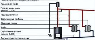
The schematic diagram of the elevator unit can be seen in the figure:
Elevator unit in the heating system: 1- shut-off valves (valve); 2 - mud trap; 3 — water jet elevator; 4 - pressure gauge; 5 - thermometer
The main elements are valves that allow you to adjust the parameters of forward and reverse flow. Mud collectors are devices that separate mechanical inclusions in the form of small debris or dirt. They are subject to periodic cleaning; filling the mud traps is dangerous and can damage elements located further along the flow path. The remaining elements - pressure gauges and thermometers - are control elements and allow you to monitor the current mode of the heating system.
Elevator with adjustable nozzle.
Now we just have to figure out how to more easily regulate the temperature at the elevator outlet
, and is it possible to save heat using an elevator?
It is possible to save heat using a water jet elevator, for example, by lowering the room temperature at night
, or during the day when most of us are at work.
Although this issue is also controversial, we lowered the temperature, the building cooled down, therefore, in order to reheat it, the heat consumption must be increased against the norm. There is only one benefit: at a cool temperature of 18-19 degrees, we sleep better
, our body feels more comfortable.
Wednesday is assumed to last. It is complete - if it is equipped with all the elements that allow it to function as intended. It is suitable for use - if it is technically and legally legal in the form of statements, approvals and permissions for use.
The tax authorities assume that installations, systems and equipment installed in buildings can be considered complete and fit for use if. Enable all structural components to function as intended; This does not mean, however, that they are capable of self-employment.
For heat saving purposes, a special water jet elevator with an adjustable nozzle
. Structurally, its design and, most importantly, the depth of quality adjustment can be different. Typically, the mixing coefficient of a water-jet elevator with an adjustable nozzle varies in the range from 2 to 5. As practice has shown, such adjustment limits are quite sufficient for all occasions. Danfoss offers a control range of up to 1 in 1000. Why this is used in a heating system is completely unclear to us. But the price ratio in favor of a water jet elevator with an adjustable nozzle relative to Danfoss regulators is approximately 1 to 3. True, we must pay tribute to Danfos, their products are more reliable, although not all of them; some varieties of inexpensive three-way valves do not work well on our water. Recommendation – you need to save wisely!
Basic elements of the elevator
They are not permanently connected to the building, i.e. they can be switched off without damaging the building structure or installations, systems and devices. To determine whether a particular item can be considered permanent or not, you must use the classification of fixed assets.
Advantages of water jet elevators
Of course, this does not mean that every installation, system or device installed in a building can be a self-contained environment. For this to happen, the component in question. He must be classified as a permanent agent in the CST and must not be presented at the same time as the clarification in the building equipment.
Fundamentally, all regulating elevators are designed in the same way. Their device is clearly visible in the figure.
. , you can see an animated image of the operation of the VARS control mechanism of a water-jet elevator.
And finally, a short comment - the use of water-jet elevators with an adjustable nozzle
especially
effective in public and industrial buildings
where it allows you to save up to 20-25% of heating costs by lowering the temperature in heated rooms at night and, especially, on weekends.
The opinion of the statistical office will be useful
It cannot be permanently connected to the building, i.e. it can be switched off without damaging the building, installation, system or equipment. Classification of durable means is a systematic collection of objects of durable properties. For accounting purposes, establish depreciation rates and statistical tests. The allocation of a given measure for the corresponding classification of fixed assets is determined by its purpose, design and equipment.
The authority authorized to do this is the statistical office. Therefore, the reader should contact the statistical office for assistance in classifying the asset. The statistical conclusion of the classification bureau will be important evidence before the tax authorities.
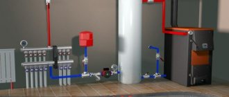
The elevator unit of the heating system is used to connect the house to an external heating network (heat supply source) if it is necessary to reduce the temperature of the coolant by mixing water from the return pipeline.
How the device works
The device is a fairly large container, as it includes a mixing chamber. Dirt traps and magnetic mesh filters are installed in front of the chamber: the quality of tap water in our cities is never high. The photo shows a diagram of a heating elevator.
Purified water enters the mixing chamber at high speed. Due to the vacuum, the return water is sucked in spontaneously and mixed with the superheated water. The coolant is supplied to the network through a nozzle. It is clear that the size of the hole in the nozzle determines the water temperature and pressure. Devices with an adjustable nozzle and a constant one are produced; their general operating principle is the same.
A certain ratio must be maintained between the pressure inside the supply pipe and the resistance of the heating elevator: 7 to 1. With other indicators, the operation of the device will be ineffective. The pressure in the supply pipe and return pipe is also important - it should be almost the same.
Heating elevator with adjustable nozzle
The operating principle of the device is exactly the same: mixing the coolant and distributing it throughout the network due to the resulting pressure difference. However, an adjustable nozzle allows you to set different temperatures for certain times of the day, for example, and thereby save heat.
- The diameter itself does not change, but an additional mechanism is installed in the adjustable nozzle. Depending on the value indicated on the sensor, the throttle needle moves along the nozzle, reducing or increasing its working cross-section, which will change the size of the hole. The mechanism requires power to operate. The photo shows a heating elevator with an adjustable nozzle.
Public institutions and industrial facilities receive the greatest benefit from the device, since for most of them heating rooms at night is not necessary - supporting the minimum mode is quite enough. The ability to set a lower temperature at night significantly reduces heat energy consumption. Savings can reach 20–25%.
In residential apartment buildings, a device with an adjustable nozzle is used much less frequently, and in vain: at night, a temperature of +17–18 C instead of 22–24 C is more comfortable. Reducing the temperature also allows you to reduce heating costs.
- Making an artificial fireplace with your own hands
- Step-by-step instructions for making a brick tandoor
- DIY decorative fireplace made of plasterboard
- How to choose a brick for laying a fireplace
Calculation
The operation of the elevator unit depends on the correctly selected dimensions and pressure difference between the discharge and return pipelines. To calculate the parameters of the elevator unit, heating engineers and programmers have created quite a lot of programs. They look like a regular screen form with a customized formula for calculations. After filling out all the rows of the table, the program calculates the parameters of the hot water supply scheme, the dimensions of the elevator and displays the results in the form of a diagram with plotted dimensions and in the form of a table with calculations. The option for displaying results is usually presented in the form of a table.
The calculation of the heating network and the choice of elevator is described in some detail in the Building Codes and Rules:
- SNiP 23-01-99 “Building climatology”, 2000;
- SNiP II-3-79 “Construction Heat Engineering”, 1998;
- SNiP 2.04.05-91 “Heating, ventilation and air conditioning”, 1987;
- Bogoslovsky V.N. “Internal sanitary installations”, 1990.
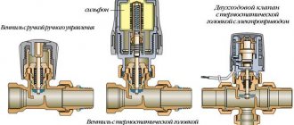
The mixing thermostat is an alternative to the standard elevator unit. It works in exactly the same way as an elevator - it mixes the hot water coming from the thermal power plant and the cooled water that returns from the radiators. Three channels are connected to the thermostat: one for hot water, the second for return, and the third for supplying the prepared mixture to the heating radiators. If the temperature of the water from the main pipeline is within acceptable limits, the cold flow is completely blocked. As soon as the temperature begins to rise, the valve gradually begins to open, a portion of cool water is added to the hot water, lowering the temperature of the mixture. The hotter the water, the larger the volume of cool water is added. A three-way mixing thermostat valve is necessary to control the proportion of cold and hot water in order to obtain the coolant at the optimal temperature. Advantages: small dimensions, no moving parts, easy temperature adjustment.
Elevator what is it
To understand and understand what this element is, it is best to go down to the basement of the building and see it with your own eyes. But if you have no desire to leave your home, then you can view the photo and video files in our gallery. In the basement, among the many gate valves, pipelines, pressure gauges and thermometers, you will definitely find this unit.
We suggest first understanding the principle of operation. Hot water is supplied to the building from the district boiler house, and cooled water is discharged.
This requires:
- Supply pipeline
– supplies hot coolant to the consumer; - Return pipeline
- performs the work of removing the cooled coolant and returning it to the district boiler room.
Several houses, and in some cases each one if the houses are large, are equipped with thermal chambers. They distribute coolant between houses, and also install shut-off valves that serve to cut off pipelines. Drainage devices can also be installed in the chambers, which are used to empty pipes, for example, for repair work. Further, the process depends on the temperature of the coolant.
In our country there are several main modes of operation of district boiler houses:
- Supply 150 and return 70 degrees Celsius;
- Respectively 130 and 70;
- 95 and 70.
The choice of mode depends on the latitude of residence. So, for example, for Moscow a 130/70 schedule will be sufficient, but for Irkutsk a 150/70 schedule will be needed. The names of these modes have the numbers of the maximum load of the pipelines. But depending on the air temperature outside the window, the boiler room can operate at temperatures of 70/54.
This is done to prevent overheating in the rooms and to make them comfortable to stay in. This adjustment is performed at the boiler room and is a representative of the central type of adjustment. An interesting fact is that in European countries a different type of regulation is performed - local. That is, adjustment takes place at the heat supply facility itself.
In this case, heating networks and boiler houses operate at maximum capacity. It is worth saying that the highest performance of boiler units is achieved precisely at maximum loads. comes to the consumer and is locally regulated by special mechanisms.
These mechanisms consist of:
- Outdoor and indoor temperature sensors;
- Servo drive;
- Actuator with valve.
Such systems are equipped with individual devices for metering thermal energy, thereby achieving great savings in monetary resources. Compared to elevators, such systems are less reliable and durable.
So, if the coolant has a temperature of no more than 95 degrees, then the main task is the high-quality physical distribution of heat throughout the system. To achieve these goals, manifolds and balancing valves are used.
But in the case when the temperature is above 95 degrees, it needs to be reduced a little. This is what elevators do in the heating system; they add chilled water from the return line to the supply pipeline.
Features and Specifications
As we have already figured out, the elevator of the heating system is responsible for cooling the superheated water to a given value. This prepared water then enters.
This element improves the quality of operation of the entire building system and, when properly installed and selected, performs two functions:
- Mixing;
- Circulation.
Advantages of the elevator heating system:
- Simplicity of design;
- High efficiency;
- No electrical connection required.
Flaws:
- We need accurate and high-quality calculation and selection of a heating elevator;
- There is no way to regulate the outlet temperature;
- It is necessary to maintain a pressure difference between supply and return of around 0.8-2 bar.
Nowadays, such elements have become widespread in heating networks. This is due to their advantages, such as resistance to changes in hydraulic and temperature conditions. In addition, they do not require constant human presence.
Design
The elevator consists of:
- Vacuum chambers;
- Nozzles;
- Jet elevator.
Among heating engineers there is a concept called piping an elevator unit. It consists of installing the necessary shut-off valves, pressure gauges and thermometers. All this is assembled and is a unit.
What is an elevator unit of a heating system
Trunk heating networks operate in three main modes:
- 95°/70°
- 130°/70°
- 150°/70°
The first number indicates the temperature of the coolant in the forward pipeline, the second – in the return. The coolant is transported over considerable distances, so the temperature is set taking into account the loss of thermal energy during movement and adjusted for climatic or weather conditions. Hence there are three options for supplying coolant - if you constantly heat water to the maximum value, fuel consumption will increase, so heating modes change depending on external conditions.
According to sanitary standards and technical characteristics of household heating equipment, the upper limit of coolant temperature should not exceed 95°. If the water is heated to 130° or 150°, it must be cooled to the set value. There are several reasons for this:
- Most heating devices are not able to work with overheated water - cast iron radiators become brittle, aluminum radiators may fail or cease to maintain system pressure.
- The pipelines used to supply coolant in apartments also have a temperature limit; for example, for plastic pipes a temperature threshold of 90° is set.
- Heating appliances that are too hot are dangerous for people, especially children.
Superheated water does not turn into steam only because there is no such possibility inside the pipelines. It requires the absence of pressure and the presence of free space, which cannot exist in a pipe. Temperature losses during transportation somewhat change the thermal regime of the coolant, but the need to cool it to operating values remains. The issue is resolved by mixing cooled water from the return line until a set temperature is obtained, suitable for use in heating appliances. Mixing of water occurs in special mechanical devices - elevators. They operate in an environment of related elements called the elevator environment, and the entire mixing unit is called the elevator unit.
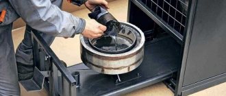
Common failures of the elevator unit
The main malfunctions of the heating system elevator can be caused by failure of the device itself due to clogging or an increase in the internal diameter of the nozzle. Also, the cause of the breakdown may be a clogged mud trap. breakdown of shut-off valves and failure of regulator settings.
The breakdown of the elevator unit of the heating system can be determined by the temperature difference before and after the device. If a strong difference is detected, it can be stated that the elevator is broken due to clogging or an increase in the diameter of the nozzle. But regardless of the breakdown, diagnostics are carried out by certified specialists. If the elevator unit is clogged, it is cleaned.
If the original diameter has increased due to corrosion, then the entire heating system will be completely unbalanced. In this case, the radiators in the rooms on the top floor will not receive thermal energy in full, and the radiators in the lower apartments will overheat greatly. To eliminate the problem, the nozzle is replaced with a new analogue with the required diameter.
Clogging of the mud traps in the elevator heating unit can be detected by changing the readings of pressure sensors located immediately before and after the device. To remove contaminants in the thermal system, they are discharged using a tap located in the lower part of the sump. If such actions do not give positive results, then the device is dismantled and mechanically cleaned.
How to adjust the elevator unit to increase the temperature in the house
One of the frequently asked questions is how to adjust the elevator unit in a central heating system in order to adjust the temperature in the house.
To do this, it is necessary to supply a larger amount of high-temperature coolant to the mixing chamber of the elevator. How can this be achieved?
To do this, the building maintenance service drills out the diameter of the nozzle or simply replaces the nozzle with a larger size.
Recently, the heat supply organization - MOEK - began to control the excessive consumption of heat in buildings and for this, during the period of pressure testing, require the Management Companies (ZhEK, REU) to hang a tag with the number of the elevator and nozzle on the elevator unit.
To do this, in the presence of an inspector, a CC mechanic must open the elevator and measure the diameter of the elevator nozzle.
All this is done with the aim of saving heat in those buildings where the elevated temperature of the return line from the house is returned to the central heating station.
But besides the positive aspects, the elevator also has negative ones.
Which ones exactly?
In the mixing chamber of the elevator, two media are mixed - the house coolant with the external coolant from the heating network. This is called - it works according to a dependent scheme, that is, the operation of the elevator depends on the “state” of the external coolant in the route.
That is, any pressure surges in the pipeline immediately affect the operation of the elevator and the heat supply to the house as a whole.
How do pressure surges in the external heating main affect the operation of the elevator unit?
Despite its simplicity, the elevator unit works well if constant pressure drops in the supply and return lines are observed.
As soon as the pressure in the supply line of the heating network drops, the pressure in the supply line of the building automatically drops.
A decrease in pressure in the supply line of the building, in turn, leads to insufficient circulation in the heating system of the house, and this leads to the fact that the last floors of the house begin to warm up poorly.
Complaints from residents about the low temperature in their apartments automatically begin to pour in. This mainly applies to houses above 5 floors.
That is, during pressure surges in the heating network, the lower floors up to and including the 5th floor do not feel anything, but the floors above begin to freeze.
But as a rule, the decrease in pressure does not last long, so within a day or two the pressure in the network returns to normal and, as a result, the temperature in the house on the upper floors normalizes.
What is a mud trap in the elevator unit of a central heating system? We will talk about this in the next article.
What is it and what is it used for
Working device in the basement
The easiest way to find out what an elevator unit is is to visit the basement of an ordinary multi-story building.
Among the many parts of the heating system, it will not be difficult to find this important component.
Let's look at a simple diagram. How does heat enter the house? There are two pipelines: supply and return. The first is to supply hot water to the house. With the help of the second, cold water from the system enters the boiler room.
The thermal chamber supplies hot water to the basement of the house
Please note that shut-off valves must be installed at the entrance
This can be a simple gate valve, or steel ball valves. The temperature of the coolant determines how it will continue to work. There are three main heat levels:
If the coolant temperature is not higher than 95° C, then all that remains is to distribute the heat throughout the entire heating system. This is where a manifold with balancing valves comes in handy.
However, everything becomes not so simple if the temperature of the coolant goes beyond the norm of 95 ° C. Such water cannot be put into the heating structure, so the heating must be reduced. This is precisely the important function of the elevator unit.
Main menu
Hello, friends! The dependent connection scheme for an internal heating system with elevator mixing in IHP is very common in the countries of the former USSR. The water-jet mechanical elevator used in this scheme is a cheap, simple and reliable device to operate. It is designed to draw in chilled water to mix with high-temperature water and transfer some of the pressure generated by the network pump at the heating plant to the heating system to circulate the water. The widespread use of such elevators was completely justified at one time.
But at the same time, a mechanical elevator has significant drawbacks. I wrote about this in this article. Perhaps the main disadvantage of the elevator is the constancy of the mixing coefficient, which excludes local regulation. That is, as the diameter of the elevator nozzle is set, it will work throughout the entire heating season, both in frost and thaw, in the same mode. And this is a very significant drawback, especially manifested at the beginning and end of the heating season, when so-called seasonal overheating occurs. Therefore, my attitude towards mechanical elevators is unequivocal - they need to be changed. As they say: “Cut without waiting for peritonitis.”
Well, what about electronic elevators with an adjustable nozzle? In them, this disadvantage (constancy of the mixing coefficient) is largely leveled out. Such elevators make it possible, within certain limits, to change the mixing coefficient to obtain water at the temperature required for the internal heating system, that is, to carry out qualitative and quantitative regulation.
In this case, the regulating body (a needle inside the nozzle), when closed, reduces the flow of network water, and at the same time causes a change in the mixing coefficient of the elevator. This can be said to be an intermediate option between a circuit with a mechanical elevator and a circuit with a circulation pump and a two or three-way valve. Of course, if finances allow, it is better to use circuits with a pump and valve. But if finance sings romances, then an acceptable option is an elevator with an adjustable nozzle.
The connection diagram with an electronic elevator certainly has the right to life. The capital costs of implementing this connection scheme are lower than those with a circulation pump.
And the savings in consumed heat energy and the reduction in monetary costs for heating with such a connection scheme are significant, and according to my observations, they are slightly inferior to schemes with a circulation pump. I have weather-sensitive elevators installed at four sites, and I must say, I am satisfied with their work. I especially like the ability to set nighttime temperature reduction modes for the heating system. It is also possible to set a decrease in the temperature of the coolant against the temperature schedule in the autumn - spring period, when there are still or no longer stable subzero temperatures outside. During this autumn-spring period, a mechanical elevator operates with great overheating and overheating.
A little about how the connection diagram with an electronic elevator is designed and works. The operation of the elevator is controlled by a controller.
It analyzes four temperatures: the outside temperature, the indoor temperature and the flow and return temperatures of your home's heating system. And in accordance with this, it sends commands to the elevator, which, with the help of a regulating needle, either increases or decreases the flow of coolant into the internal heating system. In principle, everything is simple and clear. Yes, you also definitely need a timer (it is usually sold together with the controller, or its functions are already provided in the controller).
The timer will allow you to set the hours and days when you want to set the coolant temperature to decrease against the heating supply temperature schedule.
In conclusion, we can say that the connection diagram with an electronic elevator is a good, economical option for automating ITP.
Most recently, I wrote and published the book “Design of ITP (heating points) of buildings.” In it, using specific examples, I examined various ITP schemes, namely an ITP scheme without an elevator, a heating unit diagram with an elevator, and finally, a heating unit diagram with a circulation pump and an adjustable valve. The book is based on my practical experience, I tried to write it as clearly and accessible as possible.
Here is the content of the book:
1. Introduction
2. ITP device, diagram without elevator
3. ITP device, elevator circuit
4. ITP device, circuit with a circulation pump and an adjustable valve.
5. Conclusion
You can view the book using the link below:
Installation of ITP (heating points) of buildings.
Master Class. An example of installing a heating radiator with your own hands
Let's consider the algorithm of actions when connecting a battery to a heating system.
Step 1. First, prepare and assemble the heating radiator itself. Clean all threaded holes from factory grease, for which you can use a special cleaning agent and a brush.
Radiator preparation
Step 2. When finished, remove any remaining cleaning product with a paper towel.
It is important that the holes are as clean and dry as possible.
The hole is wiped dry
Step 3. Install adapters (in our example these are ½ and ¾ inches).
Adapter
Step 4. Install the “American” faucet onto the adapter that you installed in advance. To tighten, use a special key for “American women”. As a result, you will equip a pair of holes - inlet and outlet (in the example they are located diagonally).
The “American” is installed. The key for “American” is used. The key for “American” is used.
Step 5. Install plugs on any unnecessary holes that need to be closed.
Installing the plug
Step 6. Prepare the shanks (these are special thin tubes) and cut them. Remove the internal chamfer in the shanks
Then feel the internal parts - it is important that you do not feel any burrs there
The tube (shank) is being prepared. A device for removing the internal chamfer
Step 7. Place the nut, brass spacer and rubber band on the tube (in that order). Then expand the tube using a special device, inserting it inside until it stops. After expansion, the tube will no longer be able to jump out of its place under the influence of pressure during operation of the heating system.
Pipe expansion
Step 8. Move the elastic and other parts to the extended edge, attach the adapter.
Step 9. Mark the place where the radiator will be installed on the wall, in accordance with the requirements described above. To begin, determine the center of the window sill, measure down 10 cm - the battery mounts will be located exactly at this level.
Marking
Step 10. Draw a line for installing the holders parallel to the window sill at a distance of 10 cm. The holders themselves will be attached to dowels.
Drawing a line for installing holders
Step 11. Another fastener will be located 12 cm from the floor surface along the vertical center line.
Installing the Bottom Mount
Step 12. Place the battery on the mounts and level it.
Heating radiator installation
Step 13. Mark on the wall the places where the grooves will be located (in our example, the pipes will be laid inside the wall). Do this in all places where pipes will be connected to the radiator.
Marking for future wall grooves
Step 14. Perform grooves on the previously planned areas. Remove the battery to make it easier to carry out work.
Grooving
Step 15: Prepare the tubes. Make a mark where they will be cut, as shown in the picture below.
Preparing pipes for connecting the radiator
Step 16. Connect the battery and faucet to the soft line laid in the wall. Tighten all connections tightly. The input should be located at the top, and the output, accordingly, at the bottom.
Pipe connection
Video - How to install a heating radiator
If you choose a suitable scheme and familiarize yourself with all the nuances of the connection, then installing the radiator yourself will be quick and without any problems. You just need to act carefully and do everything efficiently. The quality of heating your home depends on how correctly you do everything!