Purpose of using SART
Have you already replaced windows and doors with energy-saving ones, insulated the façade, foundation and roof? Great! But did you know that even in this case, you can reduce heat consumption by at least another 20%? We obtained this data based on the results of an energy audit of budgetary facilities in the city of Perm and the Perm region.
However, the capabilities of a programmable hardware complex go far beyond energy saving as such. An automatic flow control system is not only energy saving, but also a powerful tool for achieving living comfort, as well as a means of extending the life of a home heating network.
What functions does the automatic heat control system perform?
When developing an individual project, LEADER-Engineering specialists proceed from the need to solve all or individual tasks according to the following list:
- Providing consumers with the opportunity to create the necessary indoor microclimate themselves
- Ensuring a stable temperature of the coolant in the intra-house network, regardless of weather changes and fluctuations in the operating mode of the generating company.
- Maintaining a constant hot water temperature.
- Possibility to program changes in heating intensity depending on the days of the week and time of day.
- Saving money by eliminating excessive heat consumption.
- Ensuring a safe hydraulic heating mode (limiting the coolant pressure in the intra-house network and protecting it from water hammer).
- Freeze protection of the steam-water heating circuit.
- Automatic notification of the owner of the object about the occurrence of an emergency situation.
Principle of operation
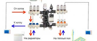
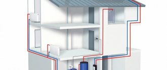
The automatic flow control system is a modular design that can be expanded depending on customer needs. Individual functions are performed by various subsystems that are part of the SART.
The key subsystem controls the flow of water or steam-water mixture depending on the task entered into the processor and 4 parameters. This is the coolant flow, the air temperature in the room, as well as the temperature of the coolant at the entrance to the heating circuit and at the exit from it, the temperature graph of the object. For feedback, parameters taken from outside air temperature sensors and on pipelines, both from the system itself and from the converters included in the heat energy meter, are used.
All subsystems are connected to a single processor unit, but each requires the installation of its own elements and connections. For example, to provide protection against freezing of the local network, an automatic system is installed to drain water from the home heating circuit. It is triggered when there is an immediate threat of freezing water in the pipes. This can happen when, at subzero temperatures, a heating plant or boiler room fails, or the circulation pump that ensures the passage of coolant through the heating circuit of the facility fails.
Saving heat, heating, heat supply.
How are savings achieved?
- The consumer himself decides when and how much heat to consume.
- Even distribution of heat throughout the house.
- Prevention of overheating and overheating in residential buildings and enterprises.
- No boiling of plate or shell-and-tube heat exchangers.
- Limiting the flow of excess coolant into the house.
- Increasing the service life of pipelines and heating systems.
- ITP control online, with notification of emergency situations.
- You don't pay for someone else's unused heating during the thaw.
Comfort of living.
- There is no need to use electric heaters.
- Drafts due to wide open windows and balcony doors are a thing of the past.
- The stuffiness in the apartment is not a nuisance.
- You no longer have cold batteries.
Automatic control system for heating and heat supply of the building.
The facility operates without permanent maintenance personnel, and information is displayed on the dispatch control panel or on a cell phone.
The remote control function allows you to change system settings from a distance and adjust its operation manually. See system parameters online.
Central heating points provide residents with heat year-round during the heating season. The main task of the ITP automated control system is round-the-clock monitoring and control of the supply of coolant with constant pressure, maintaining the set temperature in the room. For efficient service, information from actuators and sensors is collected and transmitted to a single dispatch console via wired (cable Internet) and wireless (cellular) communications. This allows you to monitor the operation of the ACS equipment of a heating point in real time and, if necessary, adjust the operating parameters of the equipment.
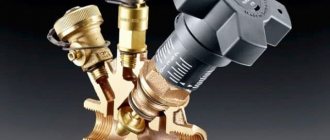
Heat, heating, heat supply regulators.
The regulators are designed to automatically change the coolant flow in the heating system at central and individual heating points, as well as to automatically regulate the temperature in supply ventilation systems by acting on an electrically driven valve. The devices provide for regulation of the difference in water temperatures in the supply and return pipelines of heating systems or the temperature of water in the supply pipeline according to the schedule of heating systems, depending on the outside air temperature. Moreover, the regulator, at a certain value of the outside air temperature and its further decrease, maintains a constant value of the regulated parameter of the coolant, excluding misadjustment of heating networks operating according to a schedule with an upper cut-off. The regulator provides for correction of the heat supply schedule when the internal air temperature deviates from the set value.
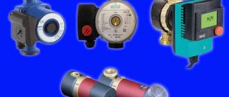
Circulation and correction pumps.
Pumps in the automation system perform a very important function:
- They maintain the calculated coolant circulation in the heating system for the duration of the closure of the control valve.
- They increase the circulation rate of the coolant in the heating system in cases where the heat supply organization does not provide the calculated heat supply parameters.
Autonomy of operation of the automatic heating and heat supply system.
Our systems use a special fail-safe scheme, which allows, in case of emergencies on heating networks, to automatically transfer the system to the previous operating mode (the old way). A power outage or communications failure will not affect the normal heat supply to the building’s heating system.
How to reduce heating bills?
Insulation of facades, roofs, doors, windows will raise the temperature of the room, but will not save money, because... residents will simply begin to release excess heat through the windows, although these measures are necessary to solve the complex problem of energy saving and increasing energy efficiency.
What to do?
Automatic adjustment of the heating system will help to avoid overheating of the premises after measures have been taken to increase the thermal resistance of the enclosing structures. The system will create conditions under which heat will be supplied within reasonable sufficiency, creating comfortable living for all residents.
Adjustment of batteries and heating radiators.
Separate apartment-by-apartment heating adjustment did not take place because... Residents who are at home during the day turn up the heating in their apartment, warming themselves at this time with heat radiated from the walls, floor, and ceiling of neighboring apartments. At the end of the month, the figures in heating bills vary greatly between apartments. Many residents find this unfair.
Manual adjustment of heat, heating system.
Principle: The colder it is outside, the more intensively the heating system should work and, conversely, when the air temperature in the house rises above the limit value, the temperature of the coolant in the heating devices should decrease.
The simplest way to regulate a heating system is to manually control the operation of the control unit - limiting the flow of coolant by shutting off shut-off valves (valves, ball valves, butterfly valves). The level to which the tap is pressed can be determined by the readings of the heat meter. On the heat meter, you must select the parameter display mode – instantaneous coolant flow.
Why didn't manual adjustment catch on?
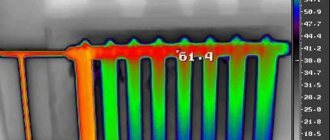
After pressing the valve, the coolant flow from the heating network drops, and the heating system of the house slows down. The circulation of water through the risers of the heating system slows down, the temperature difference between the supply and return increases. As a result of these processes, cooled coolant reaches the last batteries on the riser.
In houses with an overhead heating system , there will be excess heat on the upper floors, while the lower floors will freeze.
In houses with a lower heating system, the opposite is true - the upper floors freeze, the lower floors are forced to release excess heat to the street.
Disadvantages of Manual Heating Control:
- Coolant circulation is inhibited.
- The heating system becomes unbalanced.
- It's cold in one wing, hot in the other.
- If there is a sudden cold snap, the mechanic may not have time to open the valve.
- If the valve is closed excessively, the heat meter may generate an error.
- The shut-off valves wear out and are not intended for adjustment.
- The mechanic is tied to the heating unit.
- The need to personally respond to weather changes.
Find out more about manual adjustment!
Get a free consultation from a heating engineer!
Installation procedure and cost of the system
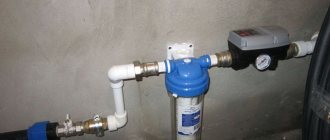
If a thermal energy meter is not installed in the building, then its installation becomes a necessary preparatory step.
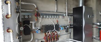
The automatic coolant flow control system is not mounted in a single housing. Its subsystems and individual elements are distributed at the input to the coolant supply unit at the heating point next to the heat meter. The only devices that are located outside this technical room are air temperature sensors in the heated room and outside.
The work is carried out within one to two weeks. To insert individual components, a temporary shutdown of the coolant supply to the facility is required. However, these operations are performed quickly, and therefore installation can be carried out during the heating season without causing significant inconvenience to consumers.
Installation is completed by carrying out adjustment work and signing an act of acceptance of the system into operation.
The price of the system is determined by the composition of components, as well as the cost of design and installation. According to the practice of our company, the total cost of SART starts from 42,000 rubles.
Regulation of thermal energy consumption. Automation of the heat consumption regulation process
A noticeable effect of saving thermal energy (up to 20-30%) in heat supply and heat consumption systems can be achieved through automatic regulation of heat consumption. In centralized heat supply systems, as a rule, high-quality regulation is carried out, that is, the temperature of the coolant changes depending on the temperature of the outside air at a relatively constant level of coolant flow. Regulation at the system level is carried out in accordance with the schedule for quality regulation of heating networks, usually twice a day, taking into account the air temperature forecast. This method of regulation cannot ensure a prompt change in the load at each heat consumption facility, taking into account its characteristics. Therefore, it is necessary to promptly regulate the load at the heat consumption facilities themselves. In this case, three main levels of regulation at facilities can be distinguished: regulation at the entrance to the facility, zonal regulation inside buildings and individual regulation in each room.
Automation tasks can be most fully and effectively implemented using individual heating points of buildings (IHP) with the ability to regulate heat consumption at the request of the consumer depending on the outside temperature, the purpose of the facility, etc. Savings when installing such IHP are achieved by compensating for the inertia of the central heating point or boiler room when the outside air temperature changes (weather compensation), as well as due to the possibility of automatically reducing the temperature inside the building at night and on weekends (for administrative buildings, educational buildings, etc.).
Requirements for equipping ITP are set out in SNiP 2.04.05-91 “Heating, ventilation and air conditioning” SNiP 2.04.07-86 “Heating networks” and SP 41-101-95 “Design of heating points”.
Automation of heating points of closed and open heat supply systems should ensure:
— maintaining the specified temperature of the water entering the hot water supply system;
— regulation of heat supply (heat flow) to heating systems depending on changes in outside air parameters in order to maintain a given air temperature in heated rooms;
— limiting the maximum water flow from the heating network to the heating point by closing the valve of the heat flow regulator for heating closed heat supply systems for individual residential and public buildings and neighborhoods with a maximum heat flow for ventilation of less than 15 %
maximum heat flow for heating or by closing the valve of the temperature regulator of water entering the hot water supply system in heating points of open heating systems and closed heat supply systems of industrial buildings, as well as residential neighborhoods and public buildings with a maximum heat flow for ventilation of more than 15% of the maximum heat flow for heating. It is possible to limit the maximum water flow from the heating network to the heating point by installing a special regulator with a valve on the supply pipeline.
— maintaining the required water pressure difference in the supply and return pipelines of heating networks at the entrance to the central heating substation or heating substation when the actual pressure difference exceeds the required one by more than 200 kPa;
— the minimum specified pressure in the return pipeline of the heating system with a possible decrease;
— maintaining the required difference in water pressure in the supply and return pipelines of heating systems in closed heat supply systems in the absence of heat flow regulators for heating, as well as installing correction pumps characterized by a change in pressure within more than 20% (in the range of operating flow rates) on the jumper between return and supply pipelines of the heating network;
— turning on and off make-up devices to maintain static pressure in heat consumption systems when they are independently connected;
— protection of heat consumption systems from an increase in pressure or temperature of water in the pipelines of these systems if the permissible parameters may be exceeded;
— maintaining a given water pressure in the hot water supply system;
— turning on and off correction pumps;
— blocking the activation of the backup pump when the working pump is turned off, protecting the heating system from emptying, stopping the supply of water to the storage tank or expansion tank when heating systems are independently connected when the upper level in the tank is reached, and turning on the make-up devices when the lower level is reached;
— turning on and off drainage pumps in underground heating points according to specified water levels in the drainage pit.