What is an elevator unit?
An elevator or thermal unit is a device that simultaneously performs the functions of an injection pump.
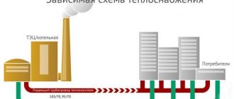
The main purpose of this design is to increase the pressure in heating networks and increase the pumping and volume of coolant in the main. The heating elevator allows you to transport coolant with a temperature of +150°C along the main line, which increases the energy efficiency of the heating system. If we compare the heat transfer of a certain volume of liquid with a temperature of +90°C with the same volume of liquid with a temperature of 150 degrees, then the amount of transported thermal energy in the second case will be significantly greater.
Describing the elevator unit of the heating system and what it is, it is worth noting that such devices allow you to quickly move coolant with a temperature above the boiling point along the main line without converting the liquid into steam. This is achieved due to the fact that high pressure is constantly maintained in the network.
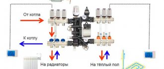
Scheme and principle of operation
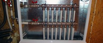
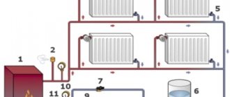
The layout of the elevator heating unit is quite simple. Externally, the design resembles a bulky tee made of metal pipes, each of which has a connecting flange at the end.
A typical diagram of an elevator heating unit looks like this:
- The left pipe resembles a nozzle, which tapers to the required design diameter.
- This is followed by the mixing chamber cylinder.
- At the bottom there is a pipe for connecting the return pipeline.
- There is another pipe on the right side. This is a special diffuser with an expansion that directs the heated coolant into the heating system.
Having examined the structure of the thermal unit elevator, it is worth understanding its connection. The supply line of the centralized heating network is connected to the left branch pipe. A return pipeline is connected to the lower branch pipe. Shut-off valves and coarse strainers are installed on both sides.
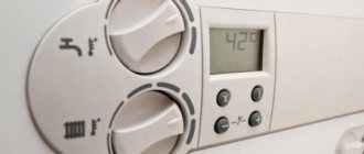
Important! The design of the heating unit must be supplemented with temperature sensors, pressure gauges and heat meters. If we consider a heating unit in an apartment building, the operating principle of the device is as follows:
If we consider a heating unit in an apartment building, the operating principle of the device is as follows:
- As the coolant passes through the pipe with the nozzle, its speed increases due to the increased fluid pressure in the line. This allows you to achieve the effect of an injection pump. Thanks to the nozzle, more efficient circulation of liquid in pipelines is ensured.
- When water enters the mixing chamber, the pressure decreases. As the jet passes through the diffuser in the mixing chamber, the medium becomes rarefied. Due to the injection effect, the high-pressure liquid carries with it water from the return line.
- Cooled and heated streams are mixed in the elevator chamber. As a result, when leaving the diffuser, the coolant has a temperature within 95 degrees.
Important! For efficient operation of the elevator unit, the pressure difference in the supply and return lines must be within certain limits in order to overcome the hydraulic resistance of the fluid
Pros and cons of a thermal unit
The elevator unit of the heating system has the following advantages:
- Reasonable cost and simplicity of design make the elevator in demand, despite its impressive age.
- This non-volatile device does not require power supply to operate.
- Thanks to the presence of a heating elevator, the cross-section of the main pipeline can be made smaller, which allows saving on its construction.
The disadvantages of this device are the impossibility of adjusting the temperature of the coolant. However, this drawback can be mitigated by using devices to adjust the nozzle diameter. In this case, control over the temperature is carried out by controlling the flow rate, which affects the degree of vacuum in the mixing chamber.
Possible problems
The heating system of a house is a complex mechanism. Some breakdowns and malfunctions are inevitable. But most often problems arise in the heating unit, namely, elevator failures. Reasons of a mechanical nature: defects in shut-off equipment, clogged filters. Because of this, a temperature difference occurs in the pipes before and after passing through the elevator. If the difference is not big, then the problem is not serious: you just need to clean the elevator. Otherwise, repairs are necessary.
Other problems with the heating unit include an increase in the permissible temperature of the measuring equipment and the occurrence of leaks in pipes. When the filters in the pipes become clogged, the pressure increases.
Important! In case of any problem, it is necessary to diagnose the entire heating system.
As already mentioned in the article, elevator units are an obsolete technology. Gradually, in apartment buildings they are being replaced by automatic heating units, which do not require constant human control and regulate all indicators themselves.
The disadvantage of such heating systems is their high cost and, like any automated device, it runs on electricity.
However, devices are built into the circuit of single-circuit units that make it possible to regulate the temperature and pressure in the incoming coolant. Thus, it allows people to save money when paying for utilities.
What is a thermal unit and how does it work?
Greetings to everyone who reads my blog! Today I want to offer you another article that is dedicated to heating. In this article I will tell you about a strange place in the basement of your house called a heating point (or heating unit). The article aims to give you a general idea of what a thermal unit is, how it works and why it is needed. Let's begin to understand these issues with the most fundamental of them.
How does an elevator work?
In simple terms, an elevator in a heating system is a water pump that does not require external energy. Thanks to this, and even its simple design and low cost, the element found its place in almost all heating points that were built in Soviet times. But for its reliable operation certain conditions are required, as will be discussed below.
To understand the structure of the heating system elevator, you should study the diagram presented in the figure above. The unit is somewhat reminiscent of a regular tee and is installed on the supply pipeline; with its side outlet it is connected to the return line. Only through a simple tee would water from the network pass directly into the return pipeline and directly into the heating system without reducing the temperature, which is unacceptable.
A standard elevator consists of a supply pipe (pre-chamber) with a built-in nozzle of the calculated diameter and a mixing chamber into which cooled coolant is supplied from the return. At the outlet of the assembly, the pipe expands, forming a diffuser. The unit operates as follows:
- coolant from the high-temperature network is directed to the nozzle;
- when passing through a hole of small diameter, the flow speed increases, which is why a rarefaction zone appears behind the nozzle;
- vacuum causes water to be sucked in from the return pipeline;
- the flows are mixed in the chamber and exit into the heating system through a diffuser.
How the described process occurs is clearly shown by the diagram of the elevator unit, where all flows are marked in different colors:
An indispensable condition for stable operation of the unit is that the pressure difference between the supply and return lines of the heating network is greater than the hydraulic resistance of the heating system.
Along with obvious advantages, this mixing unit has one significant drawback. The fact is that the operating principle of the heating elevator does not allow regulating the temperature of the mixture at the outlet. After all, what is needed for this? If necessary, change the amount of superheated coolant from the network and sucked water from the return. For example, in order to reduce the temperature, it is necessary to reduce the supply flow and increase the flow of coolant through the jumper. This can only be achieved by reducing the nozzle diameter, which is impossible.
Electric elevators help solve the problem of quality regulation. In them, by means of a mechanical drive rotated by an electric motor, the diameter of the nozzle increases or decreases. This is achieved through a cone-shaped throttle needle that enters the nozzle from the inside at a certain distance. Below is a diagram of a heating elevator with the ability to control the temperature of the mixture:
1 – nozzle; 2 – throttle needle; 3 – actuator housing with guides; 4 – shaft with gear drive.
Note. The drive shaft can be equipped with either a handle for manual control or an electric motor activated remotely.
The adjustable heating elevator, which appeared relatively recently, allows for the modernization of heating points without a radical replacement of equipment. Considering how many other similar units operate in the CIS, such units are becoming increasingly relevant.
Elevator what is it
To understand and understand what this element is, it is best to go down to the basement of the building and see it with your own eyes. But if you have no desire to leave your home, then you can view the photo and video files in our gallery. In the basement, among the many gate valves, pipelines, pressure gauges and thermometers, you will definitely find this unit.
We suggest first understanding the principle of operation. Hot water is supplied to the building from the district boiler house, and cooled water is discharged.
This requires:
- Supply pipeline
– supplies hot coolant to the consumer; - Return pipeline
- performs the work of removing the cooled coolant and returning it to the district boiler room.
Several houses, and in some cases each one if the houses are large, are equipped with thermal chambers. They distribute coolant between houses, and also install shut-off valves that serve to cut off pipelines. Drainage devices can also be installed in the chambers, which are used to empty pipes, for example, for repair work. Further, the process depends on the temperature of the coolant.
In our country there are several main modes of operation of district boiler houses:
- Supply 150 and return 70 degrees Celsius;
- Respectively 130 and 70;
- 95 and 70.
The choice of mode depends on the latitude of residence. So, for example, for Moscow a 130/70 schedule will be sufficient, but for Irkutsk a 150/70 schedule will be needed. The names of these modes have the numbers of the maximum load of the pipelines. But depending on the air temperature outside the window, the boiler room can operate at temperatures of 70/54.
This is done to prevent overheating in the rooms and to make them comfortable to stay in. This adjustment is performed at the boiler room and is a representative of the central type of adjustment. An interesting fact is that in European countries a different type of regulation is performed - local. That is, adjustment takes place at the heat supply facility itself.
In this case, heating networks and boiler houses operate at maximum capacity. It is worth saying that the highest performance of boiler units is achieved precisely at maximum loads. comes to the consumer and is locally regulated by special mechanisms.
These mechanisms consist of:
- Outdoor and indoor temperature sensors;
- Servo drive;
- Actuator with valve.
Such systems are equipped with individual devices for metering thermal energy, thereby achieving great savings in monetary resources. Compared to elevators, such systems are less reliable and durable.
So, if the coolant has a temperature of no more than 95 degrees, then the main task is the high-quality physical distribution of heat throughout the system. To achieve these goals, manifolds and balancing valves are used.
But in the case when the temperature is above 95 degrees, it needs to be reduced a little. This is what elevators do in the heating system; they add chilled water from the return line to the supply pipeline.
Features and Specifications
As we have already figured out, the elevator of the heating system is responsible for cooling the superheated water to a given value. This prepared water then enters.
This element improves the quality of operation of the entire building system and, when properly installed and selected, performs two functions:
- Mixing;
- Circulation.
Advantages of the elevator heating system:
- Simplicity of design;
- High efficiency;
- No electrical connection required.
Flaws:
- We need accurate and high-quality calculation and selection of a heating elevator;
- There is no way to regulate the outlet temperature;
- It is necessary to maintain a pressure difference between supply and return of around 0.8-2 bar.
Nowadays, such elements have become widespread in heating networks. This is due to their advantages, such as resistance to changes in hydraulic and temperature conditions. In addition, they do not require constant human presence.
Design
The elevator consists of:
- Vacuum chambers;
- Nozzles;
- Jet elevator.
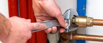
Among heating engineers there is a concept called piping an elevator unit. It consists of installing the necessary shut-off valves, pressure gauges and thermometers. All this is assembled and is a unit.
Thermal unit in an apartment building: principle of operation 2021
One of the key parts of the heating main is the thermal unit. The diagram of the heating unit, the structure and the principle of operation may seem somewhat incomprehensible to a beginner, but with minimal knowledge, you can fully understand these intricacies, which will help in the future to equip a highly efficient heating main. First of all, you should consider the basic points.
The heating point is located at the entrance of the heating main to the premises. Its main task is to change the operating parameters of the coolant fluid, and to be precise, to reduce the temperature and pressure of water before it enters the radiator or convector. This process is necessary not only to increase the safety of residents and prevent possible burning upon contact with the battery, but also to increase the service life of all equipment. The function is indispensable in cases where the building has polypropylene or metal-plastic pipes.
The relevant documentation indicates the regulated operating modes of such units. They indicate the upper and lower temperature thresholds to which the coolant can warm up. Also, according to modern standards, each unit must have a heat sensor that determines the current indicators of the liquid with which the heating unit operates.
The design, principle of operation and design of thermal equipment may depend on several features, including the design, which was created taking into account the individual requirements of customers. Among the existing types of thermal units, elevator-based models are in particular demand . This scheme is characterized by particular simplicity and accessibility, but with its help it is impossible to change the temperature of the liquid in the pipes, which causes a lot of inconvenience to the consumer. The main problem is the excessive consumption of thermal resources during temporary thaws during heating.
In a system of thermal units based on an elevator, there may be a reduced pressure reducer, which is located directly in front of the elevator. The elevator itself mixes the cooled liquid from the return pipe to the heated coolant that has reached the supply circuit.
The operating principle of the unit is based on creating a vacuum at the outlet, which significantly reduces the water pressure and starts the mixing process.
The design of a thermal unit involves a lot of components that are interdependent and function for one common purpose.
Among the main elements of the system:
- 1. Shut-off valves.
- 2. Heat meter.
- 3. Mud trap.
- 4. Coolant flow sensor.
- 5. Thermal sensor of the return pipeline.
- 6. Additional equipment.
Depending on the individual characteristics of the object, the system can be equipped with additional sensors and other components. As for installation, it must be carried out taking into account certain rules and requirements :
- 1. The installation of the scheme should take place directly at the boundaries of the balance sheet section.
- 2. Using coolant from a common communal system for individual needs is strictly prohibited.
- 3. To monitor average hourly and average daily indicators, it is necessary to take into account the operating properties of accounting equipment.
- 4. Any sensors and metering devices are fixed on the return pipeline.
There is another type of heating unit for a private house - based on a heat exchanger. In this case, a special heat exchanger is attached to the device, which separates the liquid from the heating main from the liquid in the room. This function is necessary for additional preparation of the coolant using various additives and filtering devices. The scheme expands the possibilities for regulating the pressure and temperature of the coolant inside the building. Thus, heating costs for the building are significantly reduced.
Thermostatic valves must be used to mix water at different temperatures. Such systems interact normally with aluminum radiators, but in order for the latter to last as long as possible, it is necessary to carefully select the coolant, abandoning low-quality raw materials. Of course, keeping track of the quality of the liquid is problematic, so it is better to abandon this material, giving preference to bimetallic or cast iron radiators.
The DHW connection diagram involves the use of a heat exchanger. This method provides many advantages, including :
- 1. Possibility of adjusting water temperature.
- 2. Possibility of changing the pressure of the hot coolant.
Unfortunately, many management companies do not monitor the coolant temperature, and sometimes even lower it by several degrees. The average consumer will hardly notice such changes, but on the scale of an entire home, this means saving impressive amounts of money.
In multi-apartment and multi-storey premises, administrative buildings and other objects with a large area, highly efficient thermal power plants or powerful boiler houses are used. In private cottages and small houses, simple autonomous systems are used that operate on an understandable principle.
However, even with such installations, certain problems arise that make it difficult to adjust or change operating parameters. And in large boiler houses or thermal power plants, the circuits of such equipment are much more complex and larger. A mass of branches diverge from the central pipe to each consumer. Moreover, in each of them there is a different pressure, and the volumes of heat consumed differ significantly. The length of the pipeline varies, so the system must be designed correctly so that the most distant point receives the required amount of thermal energy.
The coolant pressure difference is necessary for the normal movement of the coolant along the circuit, i.e. it is a natural alternative for pumping equipment. At the system design stage, it is necessary to adhere to the established scheme, otherwise the risk of imbalance will increase when the volume of heat consumed changes.
Moreover, strong branching of equipment should not interfere with the efficiency of heat supply. To ensure stable operation of the DSP (centralized heating system), it is necessary to equip each room with a personal elevator unit or a special automated control unit.
The designs are particularly convenient for all apartment buildings. And if someone thinks that it is possible not to use such a unit, replacing it with a natural supply of water with a slightly lower temperature, then this is a deep misconception, because in the absence of an elevator unit, it will be necessary to increase the diameter of the lines to supply a less hot coolant. If such a part is available, it will be possible to add a certain amount of coolant to the supply liquid from the return circuit, which has already cooled down sufficiently.
However, there is an opinion that the use of an elevator unit is an old method, because there are already more progressive solutions on the market, namely :
- 1. mixer with 3-way valve;
- 2. plate heat exchanger.
Unfortunately, even such a simple device as an elevator unit is subject to various failures and malfunctions. To determine the malfunction, it is necessary to analyze the readings of pressure gauges at control points.
One of the key reasons for damage to the elevator unit is a large accumulation of debris in the pipelines. Often this debris is dirt and solids in the water. If there is a sharp decrease in pressure in the heating system, a little further than the sump tank, it is necessary to clean this tank. Dirt is discharged using drainage channels, after which the grids and internal surfaces of the structure are serviced.
In the event of pressure surges, it is necessary to check the system for the presence of corrosion processes or debris. The problem may also be caused by the nozzle collapsing, causing the pressure level to become too high.
Even in the operation of elevator units, phenomena occur in which the pressure begins to increase at an incredible rate, and the pressure gauges before and after the mud tank display the same value. If this is the case, it is necessary to carry out a comprehensive cleaning of the return circuit sump. To do this, open the taps, clean the mesh and get rid of all the dirt inside.
If the nozzle dimensions have changed due to corrosion processes, a vertical misalignment of the heating circuit may have occurred. In this case, the lower radiators will warm up quite well, and the upper ones will remain cold. To eliminate the problem, you need to replace the nozzle.
Experienced engineers and heating engineers recommend using one of three operating modes of the boiler installation. Such recommendations were created taking into account theoretical data and mathematical calculations, and were also confirmed by many years of practical experience. Each of the selected modes guarantees highly efficient heat transfer with low losses. At the same time, even the large length of the highway does not affect the efficiency indicators.
This is interesting: Storage room on the landing: how to legalize it? 2021
These modes differ from each other in the different temperature ratios on the supply and return circuits:
- 1. 150/70 degrees Celsius.
- 2. 130/70 degrees Celsius.
- 3. 95/70 degrees Celsius.
When choosing the optimal ratio, it is important to take into account several factors, including regional characteristics and the average winter air temperature. If we are talking about heating a private house, it is better to refuse to use the first two modes, which involve heating the coolant to 150 and 130 degrees Celsius. At such temperatures, there is a risk of dangerous burns and other consequences from depressurization.
As is known, the liquid in the pipeline is heated to temperatures that exceed the boiling point. However, it never boils, which is due to the corresponding pressure. If it is necessary to select the optimal mode for a private building, you need to reduce the pressure and temperature, for which an elevator unit is used. The element itself is a special heating equipment, which is located at the distribution point.
Having understood the heating unit diagram, you can proceed directly to installation work. As you know, such installations are often used in multi-apartment premises that are connected to a common communal heating system.
Thermal units are designed for such tasks:
- 1. Checking and changing the operating properties of the coolant and thermal potential.
- 2. Monitoring the current state of heating systems.
- 3. Monitoring and recording the main indicators of the coolant - current temperature, pressure and volume.
- 4. Carrying out monetary calculations and drawing up an optimal energy expenditure plan.
When installing a heating system in a room, you need to understand that central heating requires certain costs. If we are talking about an apartment building, then all costs are divided among the residents. But sometimes they are unjustified due to the dishonest attitude of management companies and incorrect installation of system parts.
And in order to prevent significant financial damage, it is important to install in advance a highly efficient heating unit in a private home, which will automatically regulate any changes and select the optimal coolant temperature ratio. Only competent testing of equipment and proper maintenance will allow you to set up an effective heating system that will last for many years without failures.
In any building, including a private house, there are several life support systems. One of them is the heating system. In private houses, different systems can be used, which are selected depending on the size of the building, the number of floors, climate conditions and other factors. In this material we will analyze in detail what a thermal heating unit is, how it works and where it is used. If you already have an elevator unit, then it will be useful for you to learn about the defects and how to eliminate them.
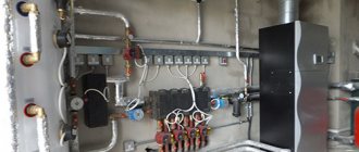
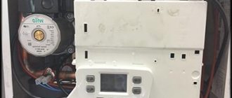
This is what a modern elevator unit looks like. The unit shown here is electrically driven. There are also other types of this product.
In simple words, a heating unit is a complex of elements that serve to connect the heating network and heat consumers. Surely readers have a question whether it is possible to install this unit yourself. Yes, you can if you know how to read diagrams. We will look at them, and one scheme will be analyzed in detail.
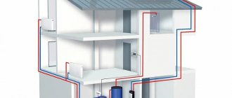
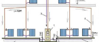
To understand how the node works, it is necessary to give an example. To do this, we will take a three-story house, since the elevator unit is used specifically in multi-story buildings. The main part of the equipment that belongs to this system is located in the basement. The diagram below will help us better understand the work. We see two pipelines:
- The server.
- Back.
Diagram of a heating unit for a multi-storey building.
Now you need to find on the diagram the thermal chamber through which water is sent to the basement. You can also notice shut-off valves, which must be installed at the entrance. The choice of fittings depends on the type of system. For the standard design, valves are used. But if we are talking about a complex system in a multi-story building, then the experts recommend using steel ball valves.
When connecting a thermal elevator unit, you must adhere to the standards. First of all, this concerns temperature conditions in boiler rooms. During operation, the following indicators are allowed:
- 150/70°C;
- 130/70°C;
- 95(90)/70°C.
When the liquid temperature is in the range of 70-95°C, it begins to be evenly distributed throughout the system due to the operation of the collector. If the temperature exceeds 95°C, the elevator unit begins to work to lower it, since hot water can damage equipment in the house, as well as shut-off valves. This is why this type of construction is used in multi-storey buildings - it controls the temperature automatically.
As you understand, the unit consists of filters, an elevator, instrumentation and fittings. If you plan to install this system yourself, then it’s worth understanding the diagram. A suitable example would be a high-rise building, in the basement of which there is always an elevator unit.
In the diagram, the system elements are marked with numbers:
1, 2 – these numbers indicate the supply and return pipelines that are installed in the heating plant.
3.4 – supply and return pipelines installed in the heating system of the building (in our case, this is a multi-storey building).
6 – this number indicates coarse filters, which are also known as mud filters.
The standard composition of this heating system includes control devices, mud traps, elevators and valves. Depending on the design and purpose, additional elements may be added to the unit.
It is worth saying that utilities become more expensive every year, and this also applies to private homes. In this regard, system manufacturers provide them with devices aimed at saving energy. For example, now the circuit may contain flow and pressure regulators, circulation pumps, pipe protection and water purification elements, as well as automation aimed at maintaining a comfortable mode.
Another variant of the thermal elevator unit diagram for a multi-storey building.
Also in modern systems a thermal energy metering unit can be installed. From the name you can understand that it is responsible for accounting for heat consumption in the house. If this device is missing, the savings will not be visible. Most owners of private houses and apartments strive to install meters for electricity and water, because they have to pay significantly less.
From the diagrams you can understand that the elevator in the system is needed to cool the overheated coolant. Some designs have an elevator, which can also heat water. This heating system is especially relevant in cold regions. The elevator in this system starts only when the cooled liquid is mixed with hot water coming from the supply pipe.
Scheme. The number “1” indicates the supply line of the heating network. 2 is the return line of the network. The number “3” indicates the elevator, 4—the flow regulator, and 5—the local heating system.
From this diagram you can understand that the unit significantly increases the efficiency of the entire heating system in the house. It works simultaneously as a circulation pump and mixer. As for the cost, the unit will be quite cheap, especially the option that operates without electricity.
But any system also has disadvantages, the collector unit is no exception:
- Separate calculations are required for each element of the elevator.
- Compression drops should not exceed 0.8-2 bar.
- Lack of ability to control high temperature.
Recently, elevators have appeared in the public utilities sector. Why did you choose this particular equipment? The answer is simple: elevators remain stable even when changes in hydraulic and thermal conditions occur in the networks. The elevator consists of several parts - a vacuum chamber, a jet device and a nozzle. You can also hear about “elevator piping” - we are talking about shut-off valves, as well as measuring instruments that allow you to maintain the normal operation of the entire system.
This is interesting: Replacement of elevators under the overhaul program in an apartment building in 2021
As mentioned above, elevators equipped with electric drives are used today. Due to the electric drive, the mechanism automatically controls the diameter of the nozzle, as a result, the temperature is maintained in the system. The use of such elevators helps reduce energy bills.
The image shows all the elements of the elevator.
The design is equipped with a mechanism that rotates due to an electric drive. Older versions use a toothed roller. The mechanism is designed so that the throttle needle can be moved in the longitudinal direction. In this way, the diameter of the nozzle changes, after which the coolant flow can be changed. Due to this mechanism, the consumption of network fluid can be reduced to a minimum or increased by 10-20%.
A common malfunction is mechanical failure of the elevator. This may occur due to an increase in the diameter of the nozzle, defects in shut-off valves, or clogged mud traps. It is quite simple to understand that the elevator is out of order - there are noticeable differences in the temperature of the coolant after and before passing through the elevator. If the temperature is low, the device is simply clogged. When there are large differences, elevator repair is required. In any case, when a malfunction occurs, diagnostics are required.
The elevator nozzle gets clogged quite often, especially in places where the water contains many additives. This element can be dismantled and cleaned. If the nozzle diameter has increased, adjustment or complete replacement of this element is necessary.
The photo shows the process of servicing the elevator heating system.
Other malfunctions include overheating of devices, leaks and other defects inherent in pipelines. As for the mud tank, the degree of its clogging can be determined by the readings of the pressure gauges. If the pressure increases after the mud filter, then the element needs to be checked. » alt=»»>
Central heat supply lines for apartment buildings are complex complexes. They transfer heat through pipelines from the supplier to the end consumer. Hot coolant is supplied through a distribution manifold and gradually fills the radiators inside the house. To equalize the temperature, a special device is used - an elevator unit.
Before understanding the diagram of the elevator heating unit, it must be said that by its design the elevator is a kind of circulation pump, which is located in the heating system along with pressure meters and shut-off valves.
Thermal elevator units perform a number of functions in their operation. To begin with, this electronic device distributes pressure in the heating system so that water is delivered to consumers into the heating radiators at a certain pressure and temperature. During circulation through pipes from the boiler room to multi-storey buildings, the volume of coolant in the circuit almost doubles. This can only happen if there is a supply of water in a separate sealed container.
From this video we will learn the principle of operation of the elevator heating unit:
It is also noteworthy that SNiP currently indicates the coolant temperature standard in the range of 65℃. But to save resources, there is active discussion about reducing this standard to 55℃. Taking into account the opinion of experts, the consumer will not feel a significant difference, and for disinfection, the thermal fluid will need to be heated to 75℃ once a day. However, these changes to SNiP have not yet been adopted, since there is no precise opinion regarding the effectiveness and appropriateness of this decision.
The diagram of the elevator unit of the heating system makes it possible to bring the temperature regime of the coolant to regulatory requirements.
This device allows you to prevent the following consequences:
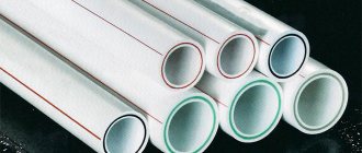
- if the wiring is made of propylene or plastic pipes, then it is not designed to supply hot thermal fluid;
- not all heating pipes are designed for prolonged exposure to elevated temperatures under high pressure - these conditions will lead to their rapid failure;
- Very hot heating radiators can cause burns if not handled carefully.
Many consumers say that the heating elevator design is irrational, and it is much easier to supply users with coolant at a lower temperature. In fact, this approach involves increasing the diameter of the central heating pipeline to circulate cooler coolant, which implies additional costs.
That is, a high-quality heating unit design allows you to use part of the cooled water from the return flow with the supply volume of coolant. Despite the fact that some elevator sources are outdated hydraulic devices, in fact, they are the most efficient in operation . There are also more modern devices that have replaced elevator unit systems.
This includes the following types of devices:
- mixer equipped with a three-way membrane;
- plate heat exchanger.
Considering the diagram of a heating elevator, one cannot help but note the similarity of the finished equipment with water pumps. Moreover, for operation there is no need to obtain energy from other systems.
In appearance, the main part of the device resembles a hydraulic tee, which is installed on the return circuit of the heating system. Through a regular tee, the coolant would easily flow into the return, bypassing the batteries. This thermal unit diagram would be inappropriate.
The standard heating elevator circuit contains the following elements :
- A preliminary chamber and a coolant supply pipe with a nozzle of a certain diameter installed at the end. Water from the return circuit circulates through it.
- A diffuser is installed at the outlet, which is designed to supply coolant to users.
Today you can find units in which the size of the nozzle is adjusted by an electric drive. Due to this, you can automatically adjust the required temperature of the circulating water.
The choice of a heating unit circuit with an electric drive is made taking into account the possibility of changing the mixing coefficient of the coolant in the range of 3-6 units. This cannot be done in elevators where the nozzle cross-section does not change. Thus, units with an adjustable nozzle can significantly reduce heating costs, which is important for multi-storey buildings with central meters.
If the heating system uses a heating unit diagram for an apartment building, then its high-quality operation can be organized only on the condition that the operating pressure between the return and supply circuits is higher than the calculated hydraulic resistance.
The operating diagram of the elevator in the thermal unit is as follows::
- hot coolant is supplied through a central pipeline to the nozzle;
- circulating through small-diameter pipes, the coolant begins to increase speed;
- and a discharged zone appears;
- the resulting vacuum “sucks” water from the return circuit;
- turbulent water flows through the diffuser to the outlet.
Despite the fact that the elevator unit has many advantages, it also has one significant drawback. It’s just that the elevator circuit does not provide for the possibility of adjusting the temperature of the outgoing coolant.
If the return water temperature indicates that it is very hot, you will need to reduce it. This problem can only be solved by reducing the size of the nozzle, but this cannot always be done due to the design features of the equipment.
In some cases, the heating unit is equipped with an electric drive, thanks to which the size of the nozzle can be adjusted. It moves the main structural element - the throttle cone needle. This needle moves a certain distance into the hole inside the nozzle. The depth of movement makes it possible to change the diameter of the nozzle and thereby regulate the temperature of the coolant.
This is interesting: Thermal energy for hot water supply in the receipt - what is it? 2021
Both a manual drive in the form of a handle and a remotely controlled electric motor can be installed on the shaft.
It must be said that the installation of this temperature regulator makes it possible to improve the overall heating system with a thermal unit without significant material costs.
Despite the reliability of the equipment, in some cases the elevator heating unit may malfunction. Hot coolant and increased pressure quickly find vulnerable areas and provoke failure of this device. This inevitably happens if individual elements are poorly assembled, the nozzle size is calculated incorrectly, or due to blockages.
Noise in the heating pipe . The elevator heating unit may create noise during operation. If this is noted, it means that unevenness or cracks have appeared at the nozzle outlet during operation.
The reason for the formation of these defects is the distortion of the nozzle, which is caused by the supply of hot water under high pressure. This can happen if excessive pressure is not throttled by the flow regulator.
The quality operation of the heating elevator can be questioned if the temperature on the input and output circuits differs significantly from the temperature graph. Most likely, the reason for this is the oversized nozzle.
A faulty throttle can lead to a change in coolant flow in contrast to the design indicator.
This violation can be easily determined by changing the temperature in the supply and return pipes. The problem can be solved by repairing the flow regulator.
If the connection diagram of the heating system to the external main is independent, then the cause of poor elevator operation can be caused by faulty water heating elements, circulation pumps, protective and shut-off valves, various leaks in equipment and pipes, and failure of regulators.
The main reasons that negatively affect the principle of operation and design of pumping equipment include the destruction of elastic membranes in the joints of the shafts of the electric motor and the pump, wear of bearings and failure of the seats under them, the appearance of cracks and irregularities in the housing, and leakage of seals. All of the above breakdowns can only be eliminated through repairs .
Poor operation of water heaters can be observed if the tightness of the pipeline is broken, sticking or destruction of the pipe assembly occurs. The problem can only be solved by replacing the pipes.
Blockages are one of the most common causes of poor-quality heat supply. Their appearance is caused by dirt getting into the heating system if the dirt filters do not cope with their task. Corrosion build-ups inside the pipeline can also increase the problem.
The level of filter contamination can be determined by the pressure gauges that are installed near the filter and behind it. A strong pressure drop can confirm or refute the assumption about the level of contamination. To clean the filters, it is necessary to remove dirt through the drain valves , which are located at the bottom of the housing.
Any malfunctions in the heating equipment and pipes system must be corrected immediately!
Any comments that do not affect the operation of the heating system must be recorded in special documentation ; it must be included in the plan for capital or routine repairs of equipment. Troubleshooting must be done in the summer before the heating season.
No one will argue that the heating system is one of the most important life support systems of any home, both a private house and an apartment. If we talk about apartments, centralized heating often predominates in them; in private houses, autonomous heating systems are most often found. In any case, the design of the heating system requires close attention. For example, in this article we will talk about such an important element as the elevator heating unit, the purpose of which is not known to everyone. Let's figure it out.
In order to clearly understand the structure and purpose of the elevator unit, you can go into an ordinary basement of a multi-story building. There, among the other elements of the thermal unit, you can find the required part.
Elevator heating unit
Let's consider a schematic diagram of the coolant supply to the heating system of a residential building. Hot water is supplied through pipelines to the house. It is worth noting that there are only two pipelines, of which:
- 1- supply (supplies hot water to the house);
- 2-reverse (removes the coolant that has released heat back to the boiler room);
Water heated to a certain temperature from the thermal chamber enters the basement of the building, where shut-off valves are installed on the pipelines at the entrance to the heating unit. Previously, gate valves were installed everywhere as shut-off valves; now they are gradually being replaced by ball valves made of steel. The further path of the coolant depends on its temperature.
In our country, boiler houses operate according to three main thermal regimes:
If the water in the supply pipeline is heated to no more than 95 0 C, then it is simply distributed throughout the heating system using a manifold equipped with control devices (balancing valves). If the temperature of the coolant is above 95 0 C, then according to current standards such water cannot be supplied to the heating system. You need to cool it down. This is where the elevator unit comes into play. It is worth noting that the elevator heating unit is the cheapest and simplest way to cool the coolant.
With the help of an elevator, the temperature of the superheated water drops to the calculated temperature, after which the prepared coolant is sent to the heating devices. The operating principle of the elevator unit is based on mixing superheated coolant from the supply pipeline with cooled water from the return pipe.
The diagram of the elevator assembly below clearly shows that the elevator performs 2 functions at once, which makes it possible to increase the overall efficiency of the heating system:
- Works as a circulation pump;
- Performs mixing function;
Elevator unit diagram
The advantage of the elevator is its simple design and, despite this, high efficiency. Its cost is low. It does not require an electrical connection to operate.
It is worth mentioning the disadvantages of this element:
- There is no possibility of regulating the outlet water temperature;
- The pressure difference between the supply and return pipelines should not fall outside the range of 0.8-2 Bar;
- Only accurate calculation of every detail of the elevator guarantees its efficient operation;
Today, elevators are still widely used in heating units of residential buildings, since the efficiency of their operation does not depend on changes in thermal and hydraulic conditions in heating networks. In addition, the elevator unit does not require constant supervision, and to adjust it, it is enough to select the correct nozzle diameter. It is worth remembering that the entire selection of elevator unit elements should be trusted only to specialists who have the appropriate permits.
Elevator diagram
In addition, the elevator unit includes the so-called “elevator piping”, consisting of control pressure gauges, thermometers, and shut-off valves. Recently, elevators have appeared equipped with an electric drive to regulate the diameter of the nozzle. Such an elevator allows you to automatically regulate the temperature of the coolant entering the heating system. However, such models are not yet widely used due to the low degree of reliability.
Technologies used in the public utilities sector are constantly evolving. Elevators are being replaced by thermal units with automatic temperature control of the supply and return coolant. They are more economical and compact, but their cost compared to an elevator is quite high. In addition, they require an electrical connection to operate.
»
Other
Removal of bulky waste: rules and features 2021
Read more
Great article 0
Advantages and disadvantages
The practicality of the heating elevator is due to the following advantages:
- simplicity of the device and, as a result, minimal maintenance;
- durability;
- low cost;
- energy independence (functions without electricity);
- independence of the mixing coefficient from the hydraulic regime in the external network;
- the presence of an additional function: the unit plays the role of a circulation pump.
The characteristic “disadvantages” of this technology are:
- lack of ability to regulate outlet temperature;
- the need for a pressure difference between the supply and return lines in the range of 0.8 - 2 atm;
- complexity and high accuracy of calculating the diameter of the cone nozzle and the dimensions of the mixing chamber.
Flaws
- The outlet temperature is not always adjustable. For example, at a low temperature of the coolant in the heating main, after mixing with cooled water (return), water will initially flow into the internal circuit pipes, the temperature of which is not sufficient to heat the room. This problem is currently being solved by installing adjustable units. Adjustment can be carried out manually (by rotating the valve) or automatically (adjustment occurs due to the movement of the rod installed inside the nozzle, the movement occurs due to the connection of a servo drive connected to sensors);
- For stable operation of a system with an elevator unit, precise selection of design is necessary;
- Some users consider one of the disadvantages to be the material investments required to purchase additional equipment and install elevator heating units. But with proper installation of high-quality equipment, even a system with automatic control of nozzle capacity pays for itself within 3-5 years (due to savings on heating fees).
How does an elevator unit work?
Before understanding the structure of the elevator unit, we note that this mechanism is intended to connect end-users of heat to heating networks. By design, the thermal elevator unit is a kind of pump that is included in the heating system along with shut-off elements and pressure meters.
The elevator heating unit performs several functions. First of all, it redistributes the pressure inside the heating system so that water is supplied to the end consumers in the radiators at the specified temperature. When passing through pipelines from the boiler room to apartments, the amount of coolant in the circuit almost doubles. This is only possible if there is a supply of water in a separate sealed container.
As a rule, coolant is supplied from the boiler room, the temperature of which reaches 105-150 ℃. Such high rates are unacceptable for domestic purposes from a safety point of view. According to regulatory documents, the maximum water temperature in the circuit cannot exceed 95 ℃.
It is noteworthy that SanPin currently sets the coolant temperature standard within 60 ℃. However, in order to save resources, a proposal to reduce this standard to 50 ℃ is being actively discussed. According to an expert opinion, the difference will not be noticeable to the consumer, and in order to disinfect the coolant, it will need to be heated to 70 ℃ every day. However, these changes to SanPin have not yet been adopted, since there is no clear opinion about the rationality and effectiveness of such a decision.
The diagram of the elevator heating unit allows you to bring the temperature of the coolant in the system to standard values.
This node allows you to avoid the following consequences:
Batteries that are too hot can cause skin burns if handled carelessly; not all heating pipes are designed for prolonged exposure to high temperatures under pressure - such extreme conditions can lead to premature failure; if the wiring is made of metal-plastic or polypropylene pipes, it is not designed for the circulation of hot coolant.
How is the thermal unit arranged?
In general, the technical structure of each heating point is designed separately depending on the specific requirements of the customer. There are several basic schemes for the design of heating points. Let's look at them one by one.
Thermal unit based on an elevator.
The scheme of a heating point based on an elevator unit is the simplest and cheapest. Its main drawback is the inability to regulate the temperature of the coolant in the pipes. This causes inconvenience for the end user and a large overconsumption of thermal energy in the event of thaws during the heating season. Let's look at the figure below and understand how this circuit works:
In addition to what is indicated above, the thermal unit may include a pressure reducer. It is installed on the feed in front of the elevator. The elevator is the main part of this scheme, in which the cooled coolant from the “return” is mixed with the hot coolant from the “supply”. The operating principle of the elevator is based on creating a vacuum at its output. As a result of this vacuum, the coolant pressure in the elevator is less than the coolant pressure in the “return” and mixing occurs.
Thermal unit based on a heat exchanger.
A heating point connected through a special heat exchanger allows you to separate the coolant from the heating main from the coolant inside the house. The separation of coolants allows for its preparation using special additives and filtration. With this scheme, there are ample opportunities to regulate the pressure and temperature of the coolant inside the house. This allows you to reduce heating costs. To have a clear idea of this design, look at the figure below.
The mixing of coolant in such systems is done using thermostatic valves. In such heating systems, in principle, aluminum radiators can be used, but they will last for a long time only if the coolant is of good quality. If the PH of the coolant goes beyond those approved by the manufacturer, then the service life of aluminum radiators may be greatly reduced. You cannot control the quality of the coolant, so it is better to play it safe and install bimetallic or cast iron radiators.
DHW can be connected in a similar way via a heat exchanger. This offers the same benefits in terms of hot water temperature and pressure control. It is worth saying that unscrupulous management companies can deceive consumers by lowering the hot water temperature by a couple of degrees. For the consumer, this is almost unnoticeable, but on a household scale it allows you to save tens of thousands of rubles per month.
Determining the value of the thermal unit
An elevator is a non-volatile independent device that performs the functions of water-jet pumping equipment. The heating unit lowers the pressure and temperature of the coolant by mixing in cooled water from the heating system.
The equipment is capable of transmitting coolant heated to the highest possible temperatures, which is beneficial from an economic point of view. A ton of water heated to +150 C has much greater thermal energy than a ton of coolant with a temperature of only +90 C.
Operating principles and detailed diagram of the thermal unit
To understand how the equipment works, you need to understand its structure. The layout of the elevator heating unit is not complicated. The device is a metal tee with connecting flanges at the ends.
The design features are:
- the left nozzle is a nozzle tapered towards the end to the design diameter;
- Behind the nozzle there is a cylindrical mixing chamber;
- the lower pipe is needed to connect the water return circulation pipeline;
- the right pipe is a diffuser with expansion that transports hot coolant into the network.
Despite the simple design of the thermal unit elevator, the operating principle of the unit is much more complex:
- The coolant heated to a high temperature moves through the pipe into the nozzle, then under pressure the transportation speed increases, and the water quickly flows through the nozzle into the chamber. The effect of a water jet pump maintains a given intensity of coolant flow in the system.
- As water passes through the chamber, the pressure decreases and the stream passes through the diffuser, providing a vacuum in the mixing chamber. Then, under high pressure, the coolant moves the liquid returned from the heating line through the jumper. The pressure is created by the ejection effect due to the vacuum, which maintains the flow of the supplied coolant.
- In the mixing chamber, the temperature regime of the flows decreases to +95 C, this is the optimal indicator for transportation through the home heating system.
Understanding what a heating unit is in an apartment building, the principle of operation of an elevator and its capabilities, it is important to maintain the recommended pressure difference in the supply and return pipelines. The difference is necessary to overcome the hydraulic resistance of the network in the house and the device itself
The elevator unit of the heating system is integrated into the network as follows:
- the left pipe is connected to the supply line;
- lower – to pipes with reverse transportation;
- shut-off valves are mounted on both sides and are supplemented with a dirt filter to prevent clogging of the unit.
The entire circuit is equipped with pressure gauges, heat consumption meters, and thermometers. For better flow resistance, the jumper is cut into the return pipeline at an angle of 45 degrees.
Advantages and disadvantages of thermal units
A non-volatile heating elevator is inexpensive, does not need to be connected to a power supply, and works flawlessly with any type of coolant. These properties ensured the demand for equipment in houses with central heating, where a high degree of heating coolant is supplied.
Disadvantages of use:
- Maintaining the differential water pressure in the return and supply pipelines.
- Each line requires specific calculations and parameters of the heating unit. At the slightest change in liquid temperature, you will have to adjust the nozzle holes and install a new nozzle.
- There is no way to smoothly regulate the intensity and heating of the transported coolant.
Units with adjustable flow area by manual or electric drive of a gear transmission located in the antechamber are offered for sale. But in this case, the device loses its energy independence.
Construction of a thermal heating unit
The heating point of a heating system is the place where the hot water supplier's main line is connected to the heating system of a residential building, and the consumed thermal energy is also calculated.
Main types of heating points
The nodes connecting the system to a source of thermal energy are of two types:
- Single-circuit;
- Dual-circuit.
A single-circuit heating point is the most common type of consumer connection to a source of thermal energy. In this case, a direct connection to the hot water supply line is used for the heating system of the house.
A single-circuit heating point has one characteristic detail - its design includes a pipeline connecting the direct and return lines, which is called an elevator. The purpose of the elevator in the heating system is worth considering in more detail.
Boiler heating systems have three standard operating modes, differing in coolant temperature (direct/return):
- 150/70;
- 130/70;
- 90–95/70.
The use of superheated steam as a coolant for the heating system of a residential building is not permitted. Therefore, if, due to weather conditions, the boiler room supplies hot water at a temperature of 150 °C, it must be cooled before being supplied to the heating risers of a residential building. For this purpose, an elevator is used, through which the “return” enters the direct line.
The elevator opens manually or electrically (automatically). An additional circulation pump can be included in its line, but usually this device is made of a special shape - with a section of sharp narrowing of the line, after which there is a cone-shaped expansion. Due to this, it works like an injection pump, pumping water from the return line.
Double-circuit heating point
In this case, the coolants of the two circuits of the system do not mix. To transfer heat from one circuit to another, a heat exchanger, usually a plate one, is used. The diagram of a double-circuit heating point is shown below.
A plate heat exchanger is a device consisting of a number of hollow plates, through some of which the heating liquid is pumped, and through the others - the heated liquid. They have a very high efficiency, they are reliable and unpretentious. The amount of heat removed is regulated by changing the number of plates interacting with each other, so taking cooled water from the return line is not required.
How to equip a heating point
h3_2
To organize heat supply to a residential building, heating points are equipped with the following additional equipment:
- Valves and valves;
- Dirt filters;
- Control and accounting devices - thermometers, pressure gauges, flow meters;
- Auxiliary pumps.
The composition of the equipment of a single-circuit heating point is shown in the figure.
The numbers here indicate the following nodes and elements:
- 1 - three-way valve;
- 2 - valve;
- 3 - plug valve;
- 4, 12 — mud collectors;
- 5 - check valve;
- 6 — throttle washer;
- 7 — V—fitting for thermometer;
- 8 — thermometer;
- 9 — pressure gauge;
- 10 — elevator;
- 11 — heat meter;
- 13 - water meter;
- 14 — water flow regulator;
- 15 — sub-steam regulator;
- 16 - valves;
- 17 - bypass line.
Installation of heat metering devices
Thermal metering equipment includes:
- Thermal sensors (installed in the forward and return lines);
- Flow meters;
- Heat calculator.
Heat metering devices are installed as close as possible to the departmental border so that the supplier company does not calculate heat loss using incorrect methods. It is best that thermal units and flow meters have gate valves or valves at their inputs and outputs, then their repair and maintenance will not cause difficulties.
Advice! There must be a section of the pipeline in front of the flow meter without changing the diameters, additional inserts and devices to reduce flow turbulence. This will increase the measurement accuracy and simplify the operation of the unit.
The thermal computer, which receives data from temperature sensors and flow meters, is installed in a separate locked cabinet. Modern models of this device are equipped with modems and can connect via Wi-Fi and Bluetooth to a local network, providing the opportunity to receive data remotely, without a personal visit to heat metering centers.
domotopim.ru
Thermal distribution point of the building
Heating engineers recommend using one of three temperature modes for boiler operation. These modes were initially calculated theoretically and underwent many years of practical application. They ensure heat transfer with minimal losses over long distances with maximum efficiency.
Thermal conditions of a boiler room can be defined as the ratio of the supply temperature to the return temperature:
- 150/70 – supply temperature is 150 degrees, and return temperature is 70 degrees.
- 130/70 - water temperature 130 degrees, return temperature 70 degrees;
- 95/70 - water temperature 95 degrees, return temperature - 70 degrees.
In real conditions, the mode is selected for each specific region based on the winter air temperature. It should be noted that high temperatures, especially 150 and 130 degrees, cannot be used for heating premises in order to avoid burns and serious consequences in case of depressurization.
The temperature of the water exceeds the boiling point and it does not boil in the pipelines due to the high pressure. This means that it is necessary to reduce the temperature and pressure and ensure the necessary heat extraction for a particular building. This task is assigned to the elevator unit of the heating system - special heating equipment located in the heat distribution point.
Structure and principle of operation
To understand how the elevator unit performs its functions, you need to understand its structure and the specifics of its operation. Structurally, the device consists of five main elements:
Construction of the elevator unit of the heating system
- Inlet pipe – supplies hot coolant at the initial temperature.
- Return pipe - supplies cooled coolant from the return circuit of the system for subsequent mixing with the hot flow.
- Nozzle - receives hot coolant, transfers it under pressure into the chamber and creates a vacuum there, as a result of which the cooled coolant is sucked in.
- Receiving chamber – ensures mixing of coolants with different temperatures.
- Outlet pipe - takes the mixed coolant of the required temperature and directs it into the pipeline for further transportation to the heating radiators.
The coolant leaves the nozzle under high pressure, so it quickly mixes and is immediately evenly distributed throughout the risers. As a result, all radiators have the same heating temperature, no matter how far they are from the elevator.
Important! To improve the quality of operation, the elevator must be equipped with dirt traps - they are necessary to clean the incoming coolant and prevent clogging of the heating system pipes.
Principle and scheme of operation
Scheme and principle of operation
The elevator helps cool superheated water to a temperature that corresponds to the norm.
The coolant then supplies it to the residential heating system. At the moment when hot water in the elevator from the supply heat pipe is mixed with cooled water from the return pipe, cooling occurs.
The layout of the elevator allows you to become more familiar with its functionality. It is not difficult to understand that it is this part of the heating system that ensures the efficiency of its operation.
It works simultaneously as 2 devices:
- Circulation pump
- Mixer
The design of the elevator is quite simple, but effective. It has a reasonable price. No electrical current is required for it to work.
However, there are some disadvantages that need to be taken into account:
- The pressure in the forward and reverse transmission pipelines must be maintained within 0.8-2 Bar;
- The outlet temperature cannot be adjusted;
- Each element of the elevator must be precisely calculated.
It is safe to say that the devices are widely used in the municipal heating system.
Elevator schematic diagram
The efficiency of their operation is not affected by fluctuations in thermal and hydraulic conditions in heating networks. In addition, the devices do not require constant monitoring. By selecting the correct nozzle diameter, all adjustments are made.
Basic elements of the elevator
Basic elements of a node
The main components of the device are:
- Jet elevator
- Nozzle
- Vacuum chamber
The elevator heating unit consists of shut-off valves, control thermometers, and pressure gauges. It is also called “elevator harness”.
New technical ideas and inventions are rapidly being introduced into our lives. District heating is no exception.
The usual elevator units are being replaced by devices that regulate the coolant automatically.
Their cost is much higher, but at the same time, these devices are more economical and energy efficient. In addition, they require power to operate. Sometimes more power is needed. Reliability on the one hand and technical progress on the other.
What will ultimately turn out to be more important, we will find out over time.
How does a heating unit with an elevator mixing unit work?
Elevator mixing units are installed in heating points of buildings that are connected to a heating network operating in a mode with high-quality regulation on “superheated” water.
Qualitative regulation involves changing the temperature of the water entering the heating system depending on the temperature of the outside air, with a constant flow of water circulating in it.
"Overheated"
water is considered if it comes from the heating network at a temperature higher than that required for supply to the heating system.
For example, a heating network can operate on a schedule of 150/70, 130/70 or 110/70, and a heating system is designed on a schedule of 95/70. The temperature graph 150/70 assumes that at the design temperature of the outside air (for Kiev this is -22°C), the temperature at the entrance of the heating networks into the house should be equal to 150°C, and it should go into the heating network at a temperature of 70°C, while This water should enter a house designed for a 95/70 schedule at a temperature of 95°C.
The elevator unit mixes the water flow from the heating network supply with a temperature of 150°C and the water flow leaving the heating system with a temperature of 70°C; as a result of mixing, a flow with a temperature of 95°C is obtained at the elevator outlet, which is supplied to the heating system.
How does mixing occur?
In the mixing chamber of the elevator unit there is a “nozzle/cone” confuser that accelerates the flow of superheated water. As the flow speed increases, the pressure in it decreases (this property is described by Bernoulli's law) so much that it becomes slightly lower than the pressure in the return pipeline. The pressure difference between the mixing chamber and the return pipeline leads to the flow of coolant through the “elevator boot” jumper from the return to the supply.
In the mixing chamber, a mixture of two streams is formed with the required temperature, but the pressure is lower than the pressure of the return pipeline. The mixture enters the elevator diffuser, in which the flow rate decreases and the pressure increases above the return pipeline pressure. The pressure increase is no more than 1.5 m.w.c., which imposes restrictions on elevator units for use in heating systems with high hydraulic resistance.
1 Cheap and easy
2 Maintenance free
3 Does not depend on the electrical network
Disadvantages of elevator mixing units
1 Not compatible with automatic regulators, therefore their joint installation is prohibited by law.
2 Creates an available pressure at the input to the heating system of no more than 1.5 m of water column, which excludes the installation of elevator heating units in buildings whose heating systems are equipped with radiator thermostatic valves.
3 The elevator unit has a constant mixing coefficient, which does not allow supplying coolant of the required temperature to the heating system if the heating network is underheated.
4 Too high sensitivity to the available pressure at the input of the heating network. A decrease in the available pressure relative to the calculated value leads to a decrease in the volumetric flow rate of water circulating in the heating system, which in turn leads to an imbalance of the system and stopping of distant risers/branches.
5 For the elevator to operate, the pressure difference between the supply and return pipelines must exceed 15 m.w.c.
Where are heating points with elevator units installed?
Almost all heating systems put into operation before 2000 are equipped with heating points with elevator units.
Where can elevator ITPs be used?
Currently, for all designed and reconstructed residential and administrative buildings, the use of automatic control at the heating point is mandatory. The use of elevator units in conjunction with automatic regulators is prohibited by regulation.
Elevator units can be installed only in facilities where there is no need for automatic control of the heating system, the available pressure (pressure difference between the supply and return pipelines) at the inlet is stable and exceeds 15 m.w.st., for the operation of the connected heating system, the pressure difference between the supply and return is sufficient return to 1.5 m.water column, and the heating system operates with a constant flow rate and is not equipped with automatic regulators.
What is an elevator unit of a heating system
Trunk heating networks operate in three main modes:
- 95°/70°
- 130°/70°
- 150°/70°
The first number indicates the temperature of the coolant in the forward pipeline, the second – in the return. The coolant is transported over considerable distances, so the temperature is set taking into account the loss of thermal energy during movement and adjusted for climatic or weather conditions. Hence there are three options for supplying coolant - if you constantly heat water to the maximum value, fuel consumption will increase, so heating modes change depending on external conditions.
According to sanitary standards and technical characteristics of household heating equipment, the upper limit of coolant temperature should not exceed 95°. If the water is heated to 130° or 150°, it must be cooled to the set value. There are several reasons for this:
- Most heating devices are not able to work with overheated water - cast iron radiators become brittle, aluminum radiators may fail or cease to maintain system pressure.
- The pipelines used to supply coolant in apartments also have a temperature limit; for example, for plastic pipes a temperature threshold of 90° is set.
- Heating appliances that are too hot are dangerous for people, especially children.
Superheated water does not turn into steam only because there is no such possibility inside the pipelines. It requires the absence of pressure and the presence of free space, which cannot exist in a pipe. Temperature losses during transportation somewhat change the thermal regime of the coolant, but the need to cool it to operating values remains. The issue is resolved by mixing cooled water from the return line until a set temperature is obtained, suitable for use in heating appliances. Mixing of water occurs in special mechanical devices - elevators. They operate in an environment of related elements called the elevator environment, and the entire mixing unit is called the elevator unit.
Operating principle of the elevator unit
The operating principle of a thermal elevator unit and a water-jet elevator. In the previous article, we found out the main purpose of the thermal elevator unit and the operating features of water-jet or, as they are also called, injection elevators. In short, the main purpose of the elevator is to lower the water temperature and at the same time increase the volume of pumped water in the internal heating system of a residential building.
Now let’s look at how a water jet elevator actually works and how it increases the pumping of coolant through the radiators in the apartment.
The coolant enters the house at a temperature corresponding to the temperature schedule of the boiler room. The temperature graph is the relationship between the temperature outside and the temperature that the boiler house or thermal power plant must supply to the heating network, and accordingly, with small losses, to your heating point (water, moving through pipes over long distances, cools down a little). The colder it is outside, the higher the temperature the boiler room produces.
For example, with a temperature chart of 130/70:
- at +8 degrees outside, the heating supply pipe should be 42 degrees;
- at 0 degrees 76 degrees;
- at -22 degrees 115 degrees;
If anyone is interested in more detailed figures, you can download temperature graphs for various heating systems here.