Introduction
Currently, industrial electric heating systems have become widespread for heating process facilities in the oil and gas industry. Many specialists of various specialties are involved in the implementation and subsequent operation of these systems, but this issue is not sufficiently covered in the technical literature, to put it mildly.
In this article we will not try to cover all types of heating elements used to build electric heating systems, but will focus on the features of the use of self-regulating heating cables (tapes), as the most rapidly developing and currently popular sources of thermal energy. All available information about self-regulating heating cables is often obtained by specialists from design and operating organizations only from manufacturers of this type of cable, who unanimously say: “Our products are of excellent quality and are practically free of drawbacks, with the possible exception of a slightly high cost in relation to other types of heating elements! Let's try to figure out whether this is really so, and what disadvantages are inherent in self-regulating heating cables.
Considering the importance of the operation of electrical heating systems of industrial facilities in the overall infrastructure of the enterprise, the question of understanding the main technical features of the use and operation of self-regulating heating cables will allow responsible operation specialists and design organizations:
- As a result of design and construction, obtain a technically sound, safe and uninterruptedly operating electric heating system.
- Reduce the cost of purchasing cables and auxiliary products.
- Reduce costs for subsequent operation of the system.
- Reduce energy costs as part of the facility's energy conservation program.
Design features and principle of operation of self-regulating heating cables
The most important step in the development of electric heating systems was the invention and start of production of heating cables based on the self-regulation effect. This invention was made while studying the properties of conductive carbon-filled plastics. The released power of such cables is significantly lower than that of resistive tapes, but thanks to the advent of effective thermal insulation materials, this power is sufficient to solve a wide range of heating issues of technological objects.
This diagram schematically shows the areas of application of various types of cables depending on the temperature of the heating object and the length of the cable line.
Due to the fact that the main advantages and disadvantages of self-regulating heating cables arise from their design features, we will consider this issue in more detail.
According to the heat dissipation scheme, these cables belong to the following type - self-regulating cables (ribbons) with heat dissipation in a conductive polymer matrix or conductive plastic elements.
Self-regulating cables are usually oval in shape and have the following typical design: two parallel conductive cores coated with a layer of semiconducting carbon-filled polymer, the so-called matrix. Layers of electrical insulation, shielding braiding and a protective shell are laid on top of the matrix.
A semiconducting matrix can be conventionally represented as a very large number of resistances connected in parallel to conductive wires. When voltage is applied to the conductive cores, a current arises in the semiconducting matrix, causing the generation of heat. Due to the release of heat, the matrix material expands and the contact bonds between individual carbon particles are broken. The matrix resistance increases, the current decreases. After some time, the current and temperature stabilize. The matrix resistance, normalized to one meter of cable, is usually several hundred Ohms.
Thanks to these properties, self-regulating heating cables have the following unique properties:
- They can be used when connecting to full voltage with any length from the minimum (tens of centimeters) to the maximum permissible. This property is especially valuable when the length of the heated pipeline is not known in advance.
- Capable of changing their heat release locally. If the temperature of a heated object in any zone rises, then the heat emission of the cable in this zone decreases. This property significantly increases the safety of the heating system and simplifies the installation process, since cables are allowed to approach and cross each other.
These positive characteristics are advertised by almost all manufacturers and suppliers. We will, however, try to understand certain shortcomings and features of this product. To do this, we will consider the main technical characteristics of self-regulating tapes, their relationship with each other, their impact on reliability and other important characteristics of the electric heating system design.
Characteristics of self-regulating heating cable
Supply voltage, Volt
Some manufacturers simply indicate the supply voltage range, for example: 220 - 275 Volts, without additional comments and a table of conversion factors for the allocated power depending on the supply voltage. The fact is that the rated power indicated in the documentation and advertising brochures of manufacturers is standardized at a supply voltage of not 220, but 230 or 240 Volts. This voltage must be confirmed with the manufacturer.
Moment one. Variations in supply voltage must be taken into account to estimate the power delivered by a self-regulating cable. Manufacturers offer special tables with coefficients for recalculating the allocated power depending on the deviation of the supply voltage from 230/240 Volts. For example, for some cable models this coefficient is 0.9. Accordingly, at a supply voltage of 220 Volts, the linear power of this cable will decrease by 10%. This fact must be taken into account at the time of design.
Second moment. For each brand of self-regulating cable, there are restrictions on the supply voltage. For example, for cables designed for a voltage of 230 Volts, a supply voltage exceeding 275 Volts is unacceptable. An increase in the supply voltage (for example, due to installation errors, sometimes a voltage of 380 Volts is supplied to the heating section) causes increased heat generation in the matrix and its rapid degradation and complete cessation of heating, i.e., cable failure.
Rated power per linear meter of cable, W/m at the indicated temperature in degrees Celsius
Due to the fact that this is the main technical characteristic of this product, we will dwell on it in more detail.
The significant dependence of heat generation power on temperature dictates certain rules for rationing and measuring thermal power. The power of a self-regulating tape is rated under the following standard conditions - a piece of cable being measured is installed on a metal pipe with a diameter of at least 50 mm. so as to ensure good thermal contact. Coolant is pumped through the pipe at a temperature of 10 ± 0.5 °C. (in some cases, measurements are carried out at 5 °C). The pipe with the cable is covered with thermal insulation with a thickness of at least 20 mm. The rated power indicated in manufacturers' catalogs is the power measured under standard conditions. To remove the dependence of power on temperature, it is necessary to set and maintain the appropriate pipeline temperature.
The dependence of power on temperature is measured in such an installation for at least three pipeline temperatures. The power curves of specific brands of cables versus temperature, given in the catalogs of supplier companies, show the dependence of the heat release power on the temperature of the pipe, and not on the temperature of the cable. This is a very significant point that should be taken into account when using self-regulating tapes. The following figure shows a similar relationship for the BTV2-CT cable from Tyco - Raychem.
Under other conditions, such as poor contact with the heated object, the power generated by the self-regulating cable will not correspond to the reference curve. If a self-regulating cable is suspended freely in the air, then due to the deterioration of heat transfer conditions, the measured power will be approximately 30% less than the normalized one.
Conclusion: It is important to ensure proper control over installation work on site to ensure the required quality of work. Otherwise, the electric heating system based on self-regulating cables will operate with a drop in power relative to the design one, and this fact will lead to a significant overconsumption of electricity.
Starting current of the heating cable, Ampere
Self-regulating cables, in addition to the rated power and the dependence of power on the temperature of the pipe, are characterized by the value of the specific starting current depending on the temperature at the moment of switching on. This is the current value, normalized to one meter of cable, that occurs at the moment the power is turned on. The inrush current mostly drops off within the first minute, but complete stabilization takes approximately 5 minutes. The maximum absolute value of the inrush current is determined by the length of the heating cable, the temperature of the object and the design of the particular heating cable.
The primary area of application of self-regulating cables is heating of pipelines and tanks operated at subzero ambient temperatures. As a rule, systems are started when both pipes and thermal insulation are cold. For the purposes of designing and calculating the characteristics of a heating system at the time of start-up and operation, it is necessary to know the properties of self-regulating tapes at low temperatures. Based on their design, we can conclude that the lower the temperature, the lower the resistance of the cable heating matrix and the higher the inrush/starting current.
Due to the fact that the technical characteristics of circuit breakers against short circuits, overcurrents, earth leakage protection, the cross-section of power cables, and therefore their price directly depend on the magnitude of the starting current, design organizations and end customers should pay attention at this time close attention.
Below in the text are presented the results of studies of three brands of cables in the range from +10 to – 40 °C. The 23FSLe2-ST cable is mainly installed on pipelines with a diameter of up to 100 mm. The 31FSR2-ST cable is used for heating larger pipelines. Both cables operate stably under voltage at temperatures not exceeding 65 °C. When switched off, they can withstand up to 85°C. The medium-temperature cable 55FSS2-SF has a heat-resistant matrix, and the insulation and sheath are made of fluoropolymers.
Brief characteristics of the studied cables are given in the following table.
Studies of the dependence of characteristics on temperature were carried out in a climate chamber. At the same time, such air circulation in the chamber and other experimental conditions were ensured under which the power values measured in the chamber were close to the results obtained in a standardized installation. Measurements were carried out at temperatures: +10; +3; 0; -10; -20; -thirty; -40°C. Each cable brand was represented by three samples. Upon reaching the specified temperature, the sample was kept in the chamber for 1 hour. Then the rated voltage was applied to the sample. The starting current and its decrease as the cable warmed up were recorded. A typical table of measured values is shown below.
The following figure shows graphs for reducing the inrush current of the 23FSLe2-ST cable, constructed according to the data in this table. As the temperature decreases, both the starting and steady-state current increases. There is also a slight increase in the starting current coefficient.
In addition to the steady-state power values, inrush current coefficients have been determined for all cables, knowledge of which will help in the design of heating systems using self-regulating cables. The average values of starting and steady-state currents and the values of Kpt (starting current coefficient) are given in the following table.
Main conclusions from these studies:
- The lower the temperature, the higher the starting current.
- For some cable types, the inrush current can be more than six times the steady-state current.
- As the temperature decreases, the value of the steady-state current increases.
From the accompanying table it can be concluded that the starting current at -20° Celsius is much greater than the operating current at the maintained temperature. The fact is that self-regulating cables are characterized by high inrush current coefficients. For normal operation of the power subsystem, C series machines must be used, and the length of the section should not be more than permissible for the given cold start temperature. Relevant recommendations are given in the technical descriptions.
To reduce the values of inrush currents and simultaneously reduce the ratings of circuit breakers and cross-sections of supply power cables, it is recommended to use specialized control devices for the electrical heating system.
Cross-section of current-carrying conductor, square millimeters
The length of the heating section directly depends on the cross-sectional area of the current-carrying conductor. The use of a cable with a large cross-section of the current-carrying core will make it possible to increase the length of the heating section, reduce the number of heating sections for heating pipelines of significant length and, accordingly, reduce the number of auxiliary electrical installation products (junction boxes, power cables, etc.), i.e. save on materials and installation work.
Maximum operating temperature, degrees Celsius
This temperature should not be confused with the heating temperature of the cable during the process of somoregulation. The fact is that the self-regulating cable:
- Firstly, it heats up unevenly along the entire length, depending on the unevenness of the transfer of thermal energy to the heated surface;
- Secondly, the temperature distribution in the semiconducting matrix itself is very uneven. A diagram of this process is presented in the following figure.
Accordingly, the maximum operating temperature of a self-regulating cable is the maximum possible temperature of the technological process, or otherwise of the heated surface, which the consumer should not allow to be exceeded during operation. If, for example, the maximum operating temperature of the cable is 200 °C, then the design of the heating control subsystem must ensure that the heated surface temperature does not exceed the specified temperature when the cable is in the on state. When switched off, the cable may be briefly exposed to temperatures of 250 °C. However, this exposure in total should not exceed 1,000 hours.
Exceeding the specified values will lead to rapid degradation of the semiconducting matrix and a partial (sometimes complete) reduction in the heat-generating capacity of the cable, resulting in inefficient operation of the entire electrical heating system and excessive energy consumption.
Minimum ambient temperature, degrees Celsius
The minimum ambient temperature is the minimum temperature at which the product can still be used. Considering this technical characteristic of a self-regulating cable, you can notice a very interesting point. In technical documentation, and sometimes in certificates of conformity, this temperature is not indicated by manufacturers. Or -40 °C is indicated, which is completely insufficient for projects located in Siberia and the far north. For a small number of manufacturers, the minimum ambient temperature is the required -55/-60 °C, but the tables for calculating the maximum length of the heated circuit are compiled for a minimum temperature of -40 °C. Particular attention should be paid to this point when choosing a manufacturer, model of a self-regulating heating cable and control subsystem.
Power window – deviation of the released power from the nominal value, expressed in %
Self-regulating cables are produced with some deviation in power from the nominal value. This spread can be up to +/-30% of the nominal value. For obvious reasons, many manufacturers do not indicate this technical specification in their documentation. For the consumer, the use of a cable with a wide power window will mean either excessive consumption of the heating cable at the design stage, or excessive consumption of electricity at the operating stage of the electric heating system.
How to properly install a heating system?
There are two methods of installing a heating cable - internal and external. In the first, the cable is inserted into the pipeline, in the second, it is wound around the pipe or attached along its entire length.
Note! For internal installation, a cable of any cross-sectional shape is suitable. For external installation, it is better to prefer the tape (flattened) format of the product, which provides better contact with the surface of the pipe.
In addition to determining the laying method and cross-sectional shape, it is equally important to correctly select the power of the product. A self-regulating cable with power ratings from 10 to 60 W/linear meter is available for free sale.
We recommend that you read: How to choose a brass water-folding ball valve
For small household projects, when choosing, you can focus on the following rules:
- For internal installation, most often a cable with a power of 10 W/m will be sufficient.
- For pipelines with a diameter of ½ to ¾ inches, a self-regulating cable of 17 W/m is suitable.
- ¾ - 1 ½ inches - 27 W/m.
- Over 100 mm – 31 or more W/m.
Outdoor installation
The most common arrangement of a self-regulating cable with this installation option is in one line along the bottom of the pipeline. Firstly, this arrangement virtually eliminates the possibility of mechanical damage to the cable (when heavy objects fall from above, for example).
The second reason is that liquid media inside the pipeline accumulate mainly in the lower part, so it is this part that needs to be heated first. If the power of one cable is clearly not enough, you can do this in several ways:
- Lay around the pipeline in a spiral.
- Buy a higher power cable.
- Lay several strands of cable along the pipeline.
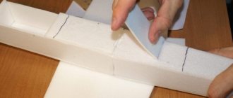
The method of fixing the cable largely depends on the material from which the pipes are made. For plastic, the best option is to secure it with aluminum tape. The adhesive tape is wrapped around the pipeline at equal distances, eliminating sagging of the heating cable. After this, the cable is additionally taped with the same tape along the entire length of the pipeline.
The cable is fixed on a metal pipeline using the ring method using heat-resistant adhesive tape or a plastic bandage.
Note! At pipeline bends, the self-regulating heating cable should be correctly positioned closer to the outer radius of the bend.
Massive components of the pipeline system (taps, fittings, flanges, etc.) require increased heating, so it is laid here according to a special scheme. The temperature sensor, on the contrary, should be installed in the coldest place in the system.
Internal installation
A special self-regulating cable with reinforced insulation is suitable for installation inside the pipeline. A tee is mounted at the cable entry point, at one end of which a seal sleeve is installed. It is worth remembering here that the prefabricated elements of the assembly must be strung on the cable until they are connected to the cold wire.
We recommend that you read: Features of cross-linked polyethylene for pipe production and their scope of application
After this, the self-regulating cable is carefully inserted into the pipeline to the required length, and the gland assembly is assembled and crimped to ensure the tightness of the entry point.
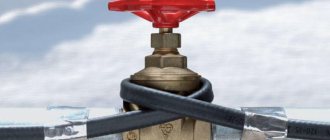
It is important! It is strictly forbidden to route the cable through shut-off valve elements (valves, gate valves, taps, etc.).
In this way, it is possible to ensure heating of only straight sections of the pipeline, or sections with a minimum number of bends. Among other disadvantages of internal installation, one can note the narrowing of the working space of the pipeline and the difficulty of its mechanical cleaning if necessary.
The influence of operating conditions on the stability of self-regulating cables
Sealing the cable during installation
Tests have shown that the self-regulating matrix is sensitive to the presence of moisture and to heating-cooling cycles. During these tests, a 3 meter long sample of 23FSLe2-ST cable with one unterminated end was immersed in water and then frozen in a cold chamber to a temperature of -5 °C. The power loss after each freezing cycle was 10%. This experiment showed how important it is to ensure reliable sealing of the ends of the self-regulating section.
Influence of thermal conductivity of heated objects on service life
Research results show that the low thermal conductivity of a plastic pipeline when heated with self-regulating cables has a very significant effect on the thermal regime of the heating cable and the pipeline itself. With constant pumping of water at a temperature of 8 °C, the temperature of the heating cable matrix installed on a plastic pipeline is 12.6 °C. exceeds the temperature of the matrix of the same cable heating a steel pipeline.
If the water flow stops, a cable installed on a steel pipeline reliably maintains the required temperature. The temperature of the matrix increases slightly due to deteriorated heat transfer, while the presence of liquid in the pipeline or its absence is practically not felt. The conducted studies show that when constructing heating systems for plastic pipelines, special attention should be paid to the technological cycle of the pipelines. If long stops in liquid pumping are expected, then it is necessary to calculate the possible loss of power of the self-regulating cable and take measures to improve heat transfer from the cable to the pipe, for example, through the use of metal foil winding and the use of heat-conducting pastes, and perhaps provide for the installation of a more powerful cable. During the period when liquid pumping through the plastic pipeline is stopped, temperature control must be strengthened. These measures should be carried out to reduce the temperature of the cable working matrix and its premature degradation.
What does degradation of the cable heating matrix mean? Degradation means a decrease in the heat-generating capacity (drop in power) of the heating cable. A cable with defects in the heating matrix may partially (or completely) lose its heat-generating properties in some sections of the cable, i.e. some sections of the cable will generate heat (heat up), and some will not. In this case, the heating system will operate with a drop in design power, which can lead, in the worst case, either to freezing of the heated equipment, or to a significant overconsumption of electricity.
Reliability of heating cables
Basically, when asked about reliability, sellers and manufacturers state the following:
- Our products are manufactured using the most modern equipment, under strict quality control.
- Some of our cables have been used without any problems for decades at certain facilities.
Is this information sufficient for the consumer?
Let us consider in more detail the issues of ensuring the reliability of cable heating elements. The reliability of cables is determined by their ability to perform their functions under given conditions for a given time. The main task of a particular cable product is determined by its purpose and design. Heating cables are designed to release a heat flux of a given specific power. Loss of performance of the tapes occurs when there are any failures. Typical types of failures of heating cables are: breakage of conductive elements, violation of the integrity of insulation and protective covers, an increase in conductor resistance above the maximum permissible standards, degradation of the heating semiconducting matrix and a corresponding decrease in heat-generating capacity.
Taking into account that a decrease in heat-generating capacity is a fundamental defect of a heating cable that affects the operation of an electric heating system, let us consider the following indicator of the reliability of heating tapes - the minimum operating time.
Minimum operating time
When applied to cables, this concept implies a period of time during which there should be no failures in the cable product. At the same time, the probability of random failures is extremely low and they are caused by design and technological flaws or violations of operating conditions. It is recommended to set the minimum operating time in the form of one of the values of the standardized series: a minimum of 500 hours and a maximum of more than 150,000 hours. It is possible to set the operating time in the form of a number of cycles - for example, on-off cycles.
For a self-regulating cable, the number of on-off cycles is a very important factor that determines the aging of the semiconducting heating matrix.
When developing new cable products, to assess their reliability, it is customary to conduct direct reliability tests to confirm a minimum operating time of 1000 hours. Specimens selected for testing are subjected to repeated test cycles. The sequence of actions in each test cycle and the number of cycles must be determined in the test program. The number of tested samples required to confirm the probability of failure-free operation of the product at the level of 0.9 with a reliability of 0.9 is 22 samples. With such a test setup, the expected number of failures (the so-called acceptance number) should be equal to zero. If one failure is allowed, the sample needs to be increased to 37 samples. Testing to obtain a greater probability of failure-free operation requires a significant increase in the number of samples, and therefore greater costs. Confirmation of operating time greater than 1000 hours significantly increases the complexity of testing.
To confirm the operating time of 1000 hours, it is recommended to request test results from the heating cable manufacturer to confirm the above reliability indicator.
The deceptive illusion of absolute reliability of cable products reduces consumer attention to such issues as facilitating operating conditions and constant monitoring of key parameters during the technological process. The main share of failures of cable products occurs when the products are operated in unacceptable modes, due to unacceptable influences that occurred during installation, or in the presence of manufacturing defects. Technological reliability, determined by the uniformity of product characteristics and the stability of technological processes, does not take into account the dynamics of changes in the characteristics of heating elements and other components of heating systems over time. With sufficiently intense heating of the tapes and simultaneous exposure to the external environment (temperature, moisture, vibrations and shocks, etc.), the polymer coatings age and the conductors oxidize. Periodically, subsequent heating and cooling cycles during operation can cause unwanted mechanical stress and degradation of the heating matrix.
Why doesn't the heating cable heat?
There are various reasons why such a system fails. First, check the thermostat and see how efficient it is. If everything is in order with this part of the structure, move on to studying the cable itself.
Integrity violation
Damage during construction and installation work often occurs if some of the main equipment is scattered nearby:
- Fastening accessories.
- Construction Materials.
- Tools to fix a self-adjusting element.
Walking along the cable in shoes with hard soles can also damage the structure.
Most often, such damage becomes especially noticeable during further installation of the system and its testing, when insulation is completed. That is, they usually find out about the problem after any finishing material has been used for the floor.
Often damage occurs due to drilling of the surface when one of the following problems needs to be solved:
- Install thresholds.
- Install plumbing fixtures.
- Installation of door stops.
To correct the problem, you need to use a special device called a megohmmeter. It measures the resistance of the insulating cable. The master records his indicator separately.
Small distances between cables, small bending radius
In this case, so-called local overheating often occurs due to the fact that adjacent turns are too close to each other. Therefore, it is so important to strictly observe the distances mentioned in the original documentation. To avoid shifting of the coils, it is enough to fix the components using polyurethane foam. This must be done when laying the floor covering.
Problems arise due to the bend radius - it can also be too small or large. Before installation, it is recommended to draw a diagram in advance showing the main components. The main thing is to take into account the technical requirements from the manufacturer.
The length of the heating wire has decreased
Sometimes the problems are due to the excess being cut off after installation. Many craftsmen do this, and then insulate the edges only with regular tape. The result is a decrease in the calculated resistance of the conductor and excessive heating of its part. The cable is working in a damaged condition.
The heating cores themselves are also often used incorrectly, which leads to violation of existing instructions. Especially when the conductors themselves are connected to the thermostat, this is strictly prohibited. If products are damaged, repair of defects should be entrusted only to experienced craftsmen.
Mistakes when arranging furniture
Some of the defects are associated with furniture that stands on the floor - with or without legs. It is not recommended to lay cables under cabinets and cabinets.
It is better to think in advance not only about the installation itself, but also about how the pieces of furniture will be arranged. Otherwise, there is a high probability that the hose or cord will be damaged.
The cable intersects with other objects of different conductivity
An example is installation in a room where a combined type of flooring is used. But most often they encounter another error.
The cable is laid under the tube, where the temperature sensor is located, which regulates the operation of the entire system. In such places, damage appears quite often.
Broken connection elements
In this case, it is recommended to start with the couplings, which are responsible for connecting to the “cold” end.
During operation, they oxidize due to the peculiarities of their structure. Especially when installation is carried out in an area subject to temperature fluctuations and exposure to large quantities of water.
Low temperature gasket
This often happens if the system is mounted:
- On the balconies.
- On the rooftops.
- With storm systems.
Manufacturers clearly indicate in their instructions that during installation the ambient temperature should be maintained within 50 degrees above zero. If this rule is violated, plastic shells lose their tightness and initial strength.
During installation there was immersion in the thermal insulation layer
Some craftsmen simply press the cables into the floor to avoid possible movement. Therefore, the heat exchange scheme initially thought out by the manufacturers is disrupted.
It is customary to connect the wire to the steel reinforcing screed using clamps. When necessary, they are raised with other heat insulators or special supports above extruded polystyrene foam.
Heterogeneous mortars
After laying tiles or pouring, it is not allowed to turn on the cable immediately after the work is completed.
With such heating, bubbles may appear inside the products, which in turn contribute to the formation of voids inside the glue or concrete. Due to such defects, the cable also deteriorates after some time.
It is important to observe the initial period of complete drying:
- Up to 10 days in the case of masonry mixtures and concrete floors.
- Up to 28 days when it comes to screed.
The thickness of the mixture is monitored separately so that the pipe and surrounding products do not deteriorate.
Defects in heating mixtures
Suppliers in this case must reimburse not only the cost of the material itself, but also the cost of replacement. Marriages are rare, but sometimes deliveries are associated with them. Then the heater is replaced.
Heating cable management systems
Almost all electric heating systems, except the most primitive ones, are equipped with a set of temperature, current, voltage sensors, control devices and information collection systems. The purpose of control subsystems (hereinafter referred to as control systems) is not only to support a given system operation algorithm, but also to provide maintenance personnel with information about its functioning.
Considering the currently available electric heating control systems, we can come to a paradoxical conclusion: customer enterprises use the most modern systems from leading manufacturers as process control systems, and the most primitive systems based on simple capillary thermostats are used as electric heating control systems. However, in the case of explosion-proof design, capillary thermostats are offered by manufacturers for very significant money.
Electric heating control systems using capillary thermostats
Let's consider a typical heating circuit control circuit based on a self-regulating heating cable using a capillary thermostat.
Block diagram elements:
- Power line.
- Automatic switch (protection against overcurrent and short circuit current).
- Residual current device/residual current device (RCD).
- Thermostat.
- Thermostat sensing element/temperature sensor.
- Heating section power cable.
- Connecting box.
- Heating cable.
- Heated pipeline.
Disadvantages of a control system using capillary thermostats:
- The need to install additional expensive RCD devices.
- Lack of monitoring and identification of increasing trends in the value of ground leakage current during operation. The fact that the heating cable fails in winter will significantly complicate repair work and cause failures in the operation of process equipment.
- Lack of control over the overheating of the heated technological surface during the technological process, in which the temperature may exceed the maximum value for this type of self-regulating heating cable, which will lead to premature failure of the cable.
- Lack of control of underheating of the heated surface during the technological process, in which the temperature may drop below the permissible value for this technological process. This temperature should not be confused with the temperature at which the heating element turns on.
- Lack of control of the minimum current consumption value of the heating section.
- Lack of control of the maximum current consumption value of the heating section.
- Lack of inrush current limitation function, i.e. stepwise supply of supply voltage to a heating cable located at a low temperature to limit the amount of inrush current.
- Lack of monitoring function for the main operating parameters of the heating cable during the summer shutdown of the electric heating system.
- Lack of a function for monitoring energy costs for the operation of the electric heating system to determine the efficiency of its operation as part of the enterprise's energy saving program.
Conclusion:
Electric heating control systems based on a self-regulating heating cable using capillary thermostats can be used in non-critical areas with a small number of heating sections and are of little use for controlling and monitoring electrical heating of main technological facilities in the oil and gas industry.
Taking into account the above information about the design and operation features of self-regulating heating cables, we can conclude that it is necessary to use specialized systems as electric heating control systems. Since the costs of troubleshooting, repairing and replacing heating sections, and downtime costs increase with the size of the industrial facility, the above systems can be recommended for use during new construction or can be added during subsequent operation.
Electric heating control systems using specialized controllers
Block diagram elements:
- Power line.
- Automatic switch (protection against overcurrent and short circuit current).
- A controller designed to control 10 heating circuits.
- Temperature sensors.
- Heating section power cable.
- Connecting box.
- Heating tape.
- Heated pipeline.
- Interface module.
- Distributed process control system (DCS).
- Automated workstation (AWS).
Read the rest of the article
Features of self-regulating electrical tape
This type of heating cable allows you to make the pipeline heating process as efficient and cost-effective as possible.
Compared to other types, self-regulating has a number of important advantages. This solution is considered very economical, since electricity is not consumed constantly, but only as needed. When cable sections overlap, the contact area will simply heat up less, without the slightest damage to the performance of the system. In such a case, the resistive cable will most likely burn out.
And one more important difference:
- Resistive cable is sold only in ready-made coils of a fixed length. Its end sleeve can only be installed correctly in the factory, so it cannot be cut. This fact can cause a lot of inconvenience, especially with internal installation.
- The self-regulating cable can be cut without affecting its performance. Most manufacturers' products have markings at the cutting points. The marking step is usually 20 or 50 cm.
We recommend that you read: Skirting for heating system pipes: how to choose and install
The only drawback of a self-regulating cable is its fairly high cost. Fortunately, developments in production technology have made it much more accessible to consumers in recent years.