One of the methods of connecting heating devices - today it is considered the most modern - involves the presence of an element called a comb.
Below in the article we will talk about how a distribution comb for heating functions and how you can make it yourself.
Why is a heating system distribution comb needed?
The comb allows you to implement the so-called radial heating system scheme. The second name for a heating comb is a distribution manifold, which is why the mentioned circuit is often called a manifold.
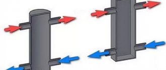
The idea is simple: we lay a separate coolant supply pipeline to each device and, in the same way, a return line. Of course, all these pipelines must be connected to a single distributor. This is what the collector comb is. This is simply a piece of pipe of a relatively large diameter, to which several bends are welded.
Distributing comb
Obviously, the system must have at least two combs: one will serve to supply the coolant, the second will collect the return.
Why is this method of organizing a heating system convenient? If the outlets on the combs are equipped with fittings (regulating on the supply, shut-off on the return), then the operator will have the following options:
- It will be possible to regulate the volume of coolant supply to a particular device from one point. Thus, it is much easier to balance (achieve an even distribution of the working medium) a collector system than a “Leningrad” or two-pipe one. It also becomes possible to set your own temperature regime for each room without leaving the spot.
- There is no need to turn off the entire system to carry out repair or maintenance work in a particular area - you only need to turn off the “beam” to which this area belongs.
- Each segment can be equipped with its own circulation pump. Thus, devices designed for different pressures of the working environment can be connected to the collector system.
- And if you equip each outlet with a heat meter, you can keep track of the consumed thermal energy for each device separately.
The comb also allows you to simultaneously connect to the system devices operating in high-temperature (radiators) and low-temperature (warm floors, pool heating) modes. In the low-temperature circuit, a jumper is installed between the supply and return, and a three-way valve with automatic control is installed.
Most of the time, the medium circulates through this circuit (this is why a jumper is needed), and when it cools down too much, the system will open the valves and a small amount of hot coolant will flow from the comb into the circuit.
How to set the heating comb?
The heating system is controlled manually according to the following parameters:
Based on coolant flow and temperature. The first indicator is determined by calculations or by design data and is established by changing the speed mode of the pump for circulating coolant. It is possible to organize monitoring of heating water consumption indicators using an installed flow meter.
The temperature mode is set manually when setting the thermostat. Allows the use of automatic adjustment; for this you will need to install servos on each heating circuit. After which the parameters can be adjusted remotely by interacting with temperature sensors.
The distribution comb of the heating system is adjusted according to the following algorithm:
- The temperature in the circuit is adjusted on a three-way ball valve. This can be done manually by setting the required liquid temperature by turning the adjustment mechanism on the thermostat. Most often, the circuit uses a thermostatic head with an external primary sensor and a pulse tube.
- Quantitative adjustment on the collector can be done either manually or automatically. By turning the cap on the valve of a separate circuit and monitoring the flow meter reading, the calculated coolant flow rate is achieved, if it is known. Otherwise, the adjustment is carried out experimentally, monitoring the operation of the system for several days; it is advisable to do this for different outside temperatures.
- Automatic adjustment consists of installing special servos instead of caps that can operate remotely with thermostats in all rooms.
It is preferable when calculations and adjustments are performed by specialists using special software applications and measuring instruments.
In order for the hydraulic mode to be maintained, the cross-sectional areas of the inlet and outlet manifolds must match, as well as their total throughput. The distribution comb of the heating system must be consistent with the maximum thermal output of the heating system of the facility. The performance of the comb is indicated in the technical documentation prepared by the device manufacturer.
For example, a heating distribution comb DN 100 mm is used for a system with a thermal power of no more than 60 kW, which is enough to heat an object of 600 m2. With a heat load of 120 kW, the comb size must be at least DN 120 mm. Only in this case can the heating network be prevented from becoming unbalanced. The calculation of the power of the circulation pump is calculated based on the specific consumption of hot water in the heating system. Each electric pump for heating circuits is calculated separately. The data obtained during the calculation process must be rounded up and a power reserve of 15% will need to be added to the result obtained.
Collector placement rules
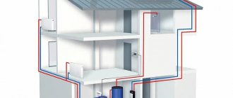
A small one-story house usually has one distribution manifold.
In this case, they try to place it in the boiler room or close to it. In two- and three-story cottages, a heating system with several collectors is used - one for each floor.
In this case, collectors can be connected both in parallel and hierarchically, when the next collector is connected to one of the branches of the previous one.
Installing your own comb on each floor allows you to reduce the total hydraulic resistance of the system and use fewer pipes.
You should think about where exactly the collector will be located during the development of the house project.
Installation of distribution comb
Installation of the comb does not bode well for easy work. As a rule, it takes a lot of time and requires the hands of a specialist who knows a lot about this matter. But, despite all the installation difficulties, they try to install this particular wiring in modern houses and apartments, since it is very effective and easy to use . New models of combs are produced taking into account the complexity of installation, this greatly facilitates the work of the master during installation. You can mount it not only in a mounting cabinet, but also to the wall; for this purpose, the kit includes mounting clamps for greater stability of the device, and its high resistance to corrosion allows the comb to serve for many years.
In order to clearly understand what a distribution comb is, you need to know about it all the information necessary for a person who does not understand anything about this matter. For a complete overview, it is worth presenting several types of different combs.
Manufacturing materials can be polymer, steel, brass or copper.
Configuration:
- Simple ones lack an important quality - control of coolant flows. Such combs divide the total flow of water by the number of nodes present in the house; they supply a uniform flow to the bathroom, kitchen, toilet and other places where water flows. The design of the comb is the simplest - a coupler with special connections on both sides and branches in the amount of 2, 3 or 4 pieces.
- Complex - have many useful additional elements: pipeline fittings; control and accounting sensor; automation _ Temperature sensors, or as they are also called, thermal sensors, are installed in combs with an electronic or mechanical system. They completely control the flow and supply of water through the pipes, especially convenient when the coolant is connected.
This material will tell you about the features of installing the North hydroshoot:
Rules for installing the comb
It is best to install the comb in such a way that all connected devices are at approximately equal distances from it. However, even with a very uneven length of the “beams”, the system will be fully operational if only the supply comb nozzles are equipped with control valves, through which balancing can be performed.
The collector can be mounted on the wall, but since it is a rather voluminous element with many protruding parts, it will be much more convenient to place it in a niche.
Installation of a heating comb
The best option is to place the distribution unit in a special metal cabinet for the heating comb, which you can buy in a store or make yourself. Among the factory-made models you can find both built-in and overhead ones.
The collector does not have to be installed in the boiler room. If there is no free space in the room, the comb can be “settled” next door, where it will not disturb anyone, for example, in a closet.
It is only important that the relative humidity in the room chosen is within normal limits - up to 60%.
Options for water supply manifolds
Adjustable and non-adjustable manifolds are available in 3/4″, 1″, 1 1/4″, 1 1/2″ and 2″ diameters. For apartments, combs with a main diameter of 3/4″ and bends of 1/2″ or d=20 mm, metric thread 24×19 (for a fitting), or Eurocone (for a compression fitting) are more often used.
The combs are divided according to the number of bends. There can be from 2 to 4, less often 5. More often, to obtain a comb with five branches, two combs with 2 and 3 branches are connected. Such installation is provided for by the design of the comb itself.
How to build a collector yourself?
Today, buying a factory-made comb is not a problem - there is a wide range of these products on sale. But the distributor, as has been shown, has an extremely simple device, so if desired, it can be made independently. As a result, you will not only save some money, but also get a collector that best suits your requirements.
Well, let's see in what order the home craftsman should act.
Collector heating system of a two-story house
Why do you need a distribution comb?
During the construction of old-type houses and apartments, main pipe routing (sequential laying) was used, which is inconvenient for modern times.
Many people faced the problem of uneven heating of apartments, and, unfortunately, no one could cope with the different pressures in the pipes. But today the problem has been solved; a solution called a distribution comb has arrived on the modern market. Unfortunately, in order to correct the situation in houses and apartments with a ready-made heating system, you will have to change the pipe layout to a collector system. If you are just planning to heat the room, this article will be useful for you. What will change after installing the distribution comb:
- The pressure in the pipes will be equalized throughout the room.
- The problem of sudden cooling of water in the bathroom when you turn on the tap in another place will disappear
- The house will be heated evenly
This is only part of all the advantages of manifold pipe routing after installing the comb. To minimize uneven water supply, the comb should be installed for both cold and hot water. Special taps are installed on it; they allow you to shut off the flow of water in a separate unit ; this is convenient in the event of a leak in the toilet or a broken tap in the bathroom.
A solar collector would be an interesting choice for heating a house:
Planning stage
To make the correct manifold for a heating system, you must have the following data:
- The number of circuits that will be connected to the node.
- An exact list of heating devices from which the heating system will be assembled, as well as their technical characteristics.
- List of additional devices that need to be equipped with a heating system. This may include pumps, fittings, buffer tanks, thermometers, pressure gauges, etc. It is important to clearly determine the model of the device, since you need to know its connection parameters.
- At least a rough plan for the future regarding system improvement: what equipment and in what quantity are you going to connect in the future? Today, devices that allow the development of alternative heat sources are becoming increasingly accessible and efficient, so it is possible that soon you will want to retrofit your system with a heat pump or solar collector.
Based on these data, it is possible to calculate the comb parameters: diameter, length, number and dimensions of bends.
A two-story house is very high-status, cozy and beautiful. But such a house must be well heated. Heating diagram for a two-story house - an overview of the types of heating systems and installation tips.
Is it necessary to install a boiler safety group? Read on. Elements included in the system.
For instructions on assembling a mixing unit for heated floors, see here:. Useful tips from the experts.
Hot water system
The device of the storage tank for heating water consists of a heat-insulated body, which contains a coil - through it, the coolant for the heating system moves from the comb, heating water for hot water supply.
This system has its own circulation pump, a set of special sensors and an actuator. When there is a strong water consumption, water is supplied to the battery from the water supply - as a result, the temperature drops. At the same time, the pump is turned on and thereby ensures the desired temperature.
The hot water supply system can be connected to the boiler:
- direct flow - if you need to heat water for domestic needs, the pump turns on and supplies it directly from the comb;
- priority - when hot water is needed, the pump in the DHW system is turned on, and the heating pump is turned off.
The second method is economically preferable, and it is mandatory to install a heating comb yourself.
Block Design Definition
Designing a collector involves finding the optimal location of bends and the distance between them. First of all, the following requirements must be taken into account:
- It is best to connect a gas or electric boiler to the highest or lowest point of the collector. A heat generator operating on solid fuel should be connected to the pipe at the end of the distributor.
- The pipeline leading to the circulation pump is also connected from the end.
- The indirect heating boiler should also be connected from the same side.
- Coolant supply lines are connected from above or below.
- The bends should be located at a distance of 100 - 200 mm from each other (between the axes). The same distance should be maintained between the feed and return combs.
Also at the design stage, you need to remember that convenient access to the fittings and devices must be provided.
Ready collector
After making the main decisions, the reservoir should be drawn to scale. The drawing will help identify shortcomings and determine which blanks and in what quantities will be needed.
To eliminate the possibility of error, the sketch must be provided with dimensions, the type and diameter of the thread on the nozzles must be marked, and, if necessary, the material of all components must be indicated.
It is very useful to mark on the image which circuit or device is connected to each tap - this will help to avoid confusion during installation.
Design and principle of operation
In the process of laying out the pipes of the heating circuits, their ends from all rooms converge in one place, where the heated floor comb is connected to them. It is a distribution and mixing unit whose task is:
- reduce the temperature of the coolant supplied from the boiler. To supply the floor system, you need water with a temperature of no more than 45 ° C, and the heat generator rarely heats the coolant to such a low threshold. Typically, the temperature at the comb inlet is at least 55 °C;
- provide the required amount of heat for each room. Here the distribution comb works as a regulator for the release of thermal energy, controlling the coolant flow in each circuit.
The distributor for underfloor heating visually resembles large heating combs installed in heating points. It also has 2 horizontal collectors - supply and return, to which consumers are connected, in our case - heating circuits. From the ends, coolant is supplied to the collector pipes from the main line - from the boiler room. A typical comb connection diagram is shown in the figure:
To regulate the amount of water flowing into each circuit, valves with a pressure rod are installed on one of the manifolds. Adjustment can be done either manually or using various automation tools, for example, servo drives. To control the amount of coolant, the outlets from the second collector are equipped with flow meter flasks. The comb structure is shown in detail in the diagram:
Here you can see that in addition to the elements listed above, an important part of the comb is the circulation pump. Without it, not a single circuit will be able to operate, since it is the pump installed between the two collectors that is responsible for circulating the coolant through the pipes.
Water in heated floors does not move naturally, only with forced impulse. Accordingly, in the absence of electricity, the system will not be able to function.
The very principle of operation of the comb is as follows. The hot water coming from the boiler enters all circuits in the required quantity, stimulated to move by the pump. Moreover, the coolant moves in a circle until its temperature drops below the set one. Since the water temperature is controlled by a three-way valve sensor, after it decreases, the valve will begin to open the way for water from the boiler line, mixing it with the cooled coolant.
When the temperature in the manifold rises to a predetermined limit, the three-way valve will shut off the line again. The comb pump for a warm water floor works non-stop, providing circulation within the system, independent of other heating networks in the house. To empty the unit, the comb design provides for the installation of drain valves. In order to release air from this separate system, the circuit can be supplemented with automatic air vents.
Sequence of work
The process of making a comb looks quite simple:
- It is necessary to purchase materials in accordance with the decisions made during the design phase of the distributor.
- Holes for bends are cut in the workpiece for the housing. If a round pipe is used for this purpose, then first you need to draw a hole pattern on paper (commonly called a “fish”). Next, the development is cut out, applied to the pipe and outlined with a pencil or marker. After this, a hole is cut out - with preliminary drilling along the contour or using a gas cutter.
- We weld the bends to the comb body using electric welding. Plugs are welded to the ends, which, if necessary, are also equipped with pipes.
- The resulting product must be checked for leaks. We leave one outlet open and close all the others tightly. After this, we fill the manifold with hot water and observe whether the welds will leak. It doesn’t hurt to get a hand pump for crimping and check the reliability of the seams under pressure.
It is not necessary to use a round pipe as the collector body; a square one will do just fine.
If the tests were successful, you can paint the comb and, after the paint has dried, begin its installation.
Even if the heated floor is installed in one room, a manifold for the heated floor is still necessary. An overview of collector models and their prices is presented on the website.
Read about the features of making an air solar collector with your own hands in this article.
Comb - what is it for?
The water circuit comb performs important functions. It increases the operating efficiency of the floor. There are 2 wires coming from the boiler - supply and return. The coolant, water, circulates through them. Each room has its own circuit; in an apartment or house there can be about 10 or even more. You need to distribute the water evenly over them. Supply is carried out according to the needs of the room in accordance with its area. A comb helps do this.
Floor heating is a low-temperature system where the coolant warms up to a maximum of 55 degrees. To create comfortable heating, you need to set a certain temperature schedule for the system - between 35 and 45 degrees. The boiler will not be able to implement this task, so it is the comb that is responsible for regulation.
Installation of a collector for heating systems of a private house
Of course, you can install a comb for the heating system. Typically, installing a heating manifold (comb) helps create the most comfortable conditions in the house by distributing heat evenly. This system is especially relevant for those homes where heated floors are used. The use of heated floors puts a lot of pressure on the heating system, but thanks to the distribution comb, the risk of an emergency is reduced. Nowadays, a variety of cabinets that house heating collectors are very popular. Such cabinets help to add aesthetics to the installation, hiding the pipes from prying eyes. The system is the same: after installation and installation, it is necessary to connect each heating device to the comb. Working with heating appliances is in many ways even more difficult than working with a water supply system. That is why people without special education and skills in this field should immediately turn to the masters of their craft.
