Heating systems in their modern form are complex structures equipped with various equipment. Their efficient operation is accompanied by optimal balancing of all their constituent elements. The hydraulic arrow for heating is designed to provide balance. It’s worth understanding its operating principle, don’t you agree?
We will talk about how a hydraulic separator works and what advantages a heating circuit equipped with it has. The article we presented describes the installation and connection rules. Helpful operating instructions are provided.
Hydraulic flow separation
The hydraulic arrow for heating is more often called a hydraulic separator. From this it becomes clear that this system is intended for implementation in heating circuits.
In heating, it is assumed that several circuits are used, for example, such as:
- lines with groups of radiators;
- underfloor heating system;
- hot water supply through a boiler.
In the absence of a hydraulic arrow for such a heating system, you will either have to make a carefully calculated design for each circuit, or equip each circuit with an individual circulation pump.
But even in these cases there is no complete certainty of achieving the optimal balance.
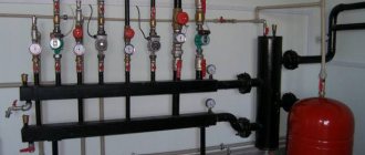
The classic design of hydraulic separators made on the basis of round or rectangular pipes can be considered approximately this way. A simple but effective solution that radically changes the state of the heating system involving the boiler
Meanwhile, the problem is solved simply. You just need to use a hydraulic separator in the circuit - a hydraulic arrow. Thus, all circuits included in the system will be optimally separated without the risk of hydraulic losses in each of them.
Hydroarrow – the name is “everyday”. The correct name corresponds to the definition – “hydraulic separator”. From a constructive point of view, the device looks like a piece of an ordinary hollow pipe (round, rectangular cross-section).
Both end sections of the pipe are plugged with metal plates, and on different sides of the body there are inlet/outlet pipes (a pair on each side).
The natural appearance of the products is hydraulic switches made from rectangular and round pipes. Both options show high efficiency. However, hydraulic guns based on round pipes are still considered a more preferable option
Traditionally, the completion of installation work on the heating system is the beginning of the next process - testing. The created plumbing design is filled with water (T = 5 – 15°C), after which the heating boiler is started.
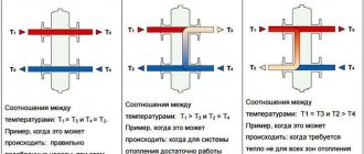
Until the coolant is heated to the required temperature (set by the boiler program), the water flow is “spinned” by the primary circuit circulation pump. Circulation pumps of secondary circuits are not connected. The coolant is directed along the hydraulic arrow from the hot side to the cold side (Q1 > Q2).
If the coolant reaches the set temperature, the secondary circuits of the heating system are activated. The coolant flows of the main and secondary circuits are equalized. In such conditions, the hydraulic arrow functions only as a filter and air vent (Q1 = Q2).
Functional diagram of the operation of a classic hydraulic switch for three different boiler operating modes. The diagram clearly indicates the distribution of heat flows for each individual operating mode of boiler equipment
If any part (for example, a heated floor circuit) of the heating system reaches a predetermined heating point, the selection of coolant by the secondary circuit temporarily stops. The circulation pump is turned off automatically, and the water flow is directed through the hydraulic arrow from the cold side to the hot side (Q1 < Q2).
The role of the hydraulic arrow in modern heating systems
In order to find out what a hydraulic arrow is and what functions it performs, first we will get acquainted with the features of the operation of individual heating systems.
Simple option
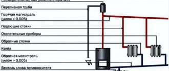
The simplest version of a heating system equipped with a circulation pump will look something like this.
Of course, this diagram is significantly simplified, since many network elements in it (for example, the security group) are simply not shown in order to “make the picture easier to understand.” So, in the diagram you can see, first of all, a heating boiler, thanks to which the working fluid is heated. Also visible is a circulation pump, through which the liquid moves through the supply (red) pipeline and the so-called “return”. Typically, such a pump can be installed both in the pipeline and directly in the boiler (the latter option is more typical for wall-mounted devices).
Note! There are also heating radiators in the closed circuit, thanks to which heat exchange occurs, that is, the generated heat is transferred to the room. If the pump is correctly selected in terms of pressure and performance, then it alone will be quite sufficient for a single-circuit system, therefore, there is no need to use other auxiliary devices
If the pump is correctly selected in terms of pressure and performance, then it alone will be quite sufficient for a single-circuit system, therefore, there is no need to use other auxiliary devices.
More complex option
If the area of the house is large enough, then the diagram presented above will clearly not be enough for it. In such cases, several heating circuits are used at once, so the diagram will look slightly different.
Here we see that through the pump, the working fluid enters the manifold, and from there it is transferred to several heating circuits. The latter include the following elements.
- A high temperature circuit (or several), in which there are collectors or ordinary batteries.
- DHW systems equipped with an indirect heating boiler. The requirements for the movement of working fluid are special here, since the temperature of water heating in most cases is regulated by changing the flow rate of the fluid passing through the boiler.
- Warm floor. Yes, the temperature of the working fluid for them should be an order of magnitude lower, which is why special thermostatic devices are used. Moreover, the contours of the heated floor have a length significantly exceeding the standard wiring.
It is quite obvious that one circulation pump cannot cope with this kind of load. Of course, today high-performance models with increased power are sold, capable of creating quite high pressure, but it is worth thinking about the heating device itself - its capabilities, alas, are not limitless. The fact is that the boiler elements are initially designed for certain pressure and performance indicators. And these indicators should not be exceeded, as this can lead to breakdown of the expensive heating installation.
In addition, the circulation pump itself, operating at the limit of its capabilities in order to supply all circuits of the network with liquid, will not be able to last long. What can we say about the loud noise and electrical energy consumption. But let's return to the topic of our article - to the hydraulic arrow for heating.
Design parameters of the hydraulic arrow
The main reference parameter for the calculation is the coolant speed in the section of vertical movement inside the hydraulic arrow. Typically the recommended value is no more than 0.1 m/s, under either of two conditions (Q1 = Q2 or Q1 < Q2).
The low speed is due to quite reasonable conclusions. At this speed, debris contained in the water flow (sludge, sand, limestone, etc.) manages to settle to the bottom of the hydraulic arrow pipe. In addition, due to the low speed, the required temperature pressure has time to form.
There are two design types of hydraulic arrows, for which calculations are usually carried out: 1 – for three diameters; 2 – by alternating pipes. Regardless of the adoption of one or another technique, the basic calculation parameters are always typical - coolant flow through the circuits and the speed parameter
The low transfer rate of the coolant promotes better separation of air from water for subsequent removal through the air vent of the hydraulic separation system. In general, the standard parameter is selected taking into account all significant factors.
For calculations, the so-called method of three diameters and alternating pipes is often used. Here the final calculated parameter is the value of the separator diameter.
Based on the obtained value, all other required values are calculated. However, to find out the size of the hydraulic separator diameter, you need the following data:
- by flow on the primary circuit (Q1);
- by flow on the secondary circuit (Q2);
- the speed of the vertical flow of water along the hydraulic arrow (V).
In fact, this data is always available for calculation.
For example, the flow rate in the primary circuit is 50 l/min. (from the technical specifications of pump 1). The flow rate on the second circuit is 100 l/min. (from the technical specifications of pump 2). The diameter of the hydraulic needle is calculated by the formula:
Formula for calculating the diameter of the hydraulic arrow pipe depending on the coolant flow parameters (flow according to the pump characteristics) and the vertical flow rate
where: Q – difference between costs Q1 and Q2; V is the velocity of the vertical flow inside the arrow (0.1 m/sec), π is a constant value of 3.14.
Meanwhile, the diameter of the hydraulic separator (conditional) can be selected using a table of approximate standard values.
| Boiler power, kW | Inlet pipe, mm | Hydraulic needle diameter, mm |
| 70 | 32 | 100 |
| 40 | 25 | 80 |
| 25 | 20 | 65 |
| 15 | 15 | 50 |
The height parameter for the heat flow separation device is not critical. In fact, any pipe height can be taken, but taking into account the supply levels of incoming/outgoing pipelines.
The use of hydraulic arrows with solid fuel equipment
When using a solid fuel unit, the hydraulic separator is connected at the inlet-outlet point.
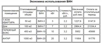
This option for connecting different types of heating devices ensures the selection of optimal and individual temperature conditions for all components separately. Today, consumers, having understood how a hydraulic heating device works, prefer ready-made products that are on sale. Select a hydraulic separator from the catalog, based on the power of the unit and the maximum water flow.
Schematic solution for shifting pipes
The classic version of a hydraulic separator involves the creation of pipes symmetrically located relative to one another. However, a circuit version of a slightly different configuration is also practiced, where the pipes are located asymmetrically. What does this give?
Manufacturing diagram of a hydraulic separator in which the secondary circuit pipes are slightly offset relative to the primary circuit pipes. According to the inventors (and proven by practice), this option seems to be more productive in filtering particles and separating air
As the practical application of asymmetrical circuits shows, in this case more efficient air separation occurs, and better filtration (sediment) of suspended particles present in the coolant is achieved.
Number of connections on the hydraulic switch
Classic circuit design determines the supply of four pipelines to the hydraulic separator structure. This inevitably raises the question of the possibility of increasing the number of inputs/outputs. In principle, such a constructive approach is not excluded. However, the efficiency of the circuit decreases with increasing number of inputs/outputs.
Let's consider a possible option with a large number of pipes, in contrast to the classics, and analyze the operation of the hydraulic separation system for such installation conditions.
Scheme of a multi-channel heat flow distribution separator. This option allows you to service larger systems, but if the number of pipes increases beyond four, the efficiency of the system as a whole decreases sharply
In this case, heat flow Q1 is completely absorbed by heat flow Q2 for the state of the system when the flow rate for these flows is actually equivalent:
Q1=Q2.
In the same state of the system, heat flow Q3 in temperature value is approximately equal to the average values of Tav. flowing through the return lines (Q6, Q7, Q8). At the same time, there is a slight temperature difference in the lines with Q3 and Q4.
If the heat flow Q1 becomes equal in thermal component Q2 + Q3, the distribution of temperature pressure is noted in the following relationship:
T1=T2, T4=T5,
whereas
T3= T1+T5/2.
If the heat flow Q1 becomes equal to the sum of the heat of all other flows Q2, Q3, Q4, in this state all four temperature pressures are equalized (T1=T2=T3=T4).
Multi-channel separation system with four inputs/four outputs, quite often used in practice. For servicing private heating systems, this solution is quite satisfactory in terms of technological parameters and stabilization of boiler operation
In this state of affairs on multi-channel systems (more than four), the following factors are noted that have a negative impact on the operation of the device as a whole:
- natural convection inside the hydraulic separator is reduced;
- the effect of natural mixing of supply and return is reduced;
- the overall efficiency of the system tends to zero.
It turns out that a departure from the classical scheme with an increase in the number of outlet pipes almost completely eliminates the working properties that a gyro shooter should have.
Hydroarrow: principle of operation, purpose and calculations
So, what is called a hydraulic arrow in the heating system of a private house? The temperature and hydraulic buffer, which ensures the processes of correlation between the return and supply temperatures, the ordered maximum flow of coolant, is called a hydraulic arrow. Why is a hydraulic arrow needed?
Can you explain very simply why a hydraulic arrow is needed in a heating system? Owners of private houses are well aware of what unbalanced heat supply means. Modern boilers have a smaller circuit. At the same time, consumer consumption during circulation is less. Using a hydraulic switch, you can separate its operation from the heat generator of the secondary circuit, increasing the reliability and quality of the system.
Hydraulic separator in the heating system
To understand why a hydraulic switch is needed in a heating system, you need to name a number of advantages of heating systems with a hydraulic thermal separator. First of all, the separator is a prerequisite for equipment manufacturers to guarantee maintenance for boilers with a capacity of up to 50 kilowatts or more. With the help of an auxiliary unit, maximum flow with laminar coolant flow is ensured. The temperature and hydraulic balance in the heating system is constantly maintained. The water gun and the heating circuit are connected in parallel. This creates minimal pressure, performance and heat losses. The supply and return pipes are located according to the knee principle. This provides a temperature gradient for the secondary circuits. If you choose the optimal hydraulic arrow for heating, you can protect the boiler from the difference in supply and return temperatures.
Equipment is protected from thermal shock. The hydraulic arrow increases the efficiency of the boiler. In addition, secondary circulation of part of the coolant in the boiler circuit is ensured. Fuel and electricity are saved. A constant volume of boiler water is maintained. If necessary, you can use a separator to compensate for the flow deficit in the secondary circuit. If the pumps have high power, then their influence can be reduced using a hollow separator. The load is supplied to the secondary circuit and the boiler.
Hydrodynamic processes in the system are stabilized by the operating principle of the hydraulic arrow. In order to extend the life of the pump, it is necessary to promptly remove mechanical impurities from the coolant. In addition, the service life of sensors, meters, and valves is extended. When dividing flows (independent consumer circuit and heat generator circuit), the hydraulic arrow ensures maximum use of the heat of combustion of the fuel.
Hydraulic separator without filter
The design of the arrow, which excludes the presence of the functions of an air separator and a sediment filter, also deviates somewhat from the accepted standard. Meanwhile, with such a design it is possible to obtain two flows with different speeds (dynamically independent circuits).
A non-standard design solution for the manufacture of hydraulic arrows. It differs from the classics in that there are no filtration or air removal functions. In addition, the distribution of heat flows has a perpendicular transport pattern, which achieves speed decoupling
For example, there is the heat flow of the boiler circuit and the heat flow of the heating device (radiator) circuit. With a non-standard design, where the direction of flow is perpendicular, the flow rate of the secondary circuit with heating devices increases significantly.
On the contrary, movement along the contour of the boiler is slower. True, this is a purely theoretical view. It is practically necessary to test under specific conditions.
How is a hydraulic arrow useful?
The need to use the classic hydraulic separator design is obvious. Moreover, on systems with boilers, the implementation of this element becomes a mandatory action.
Installing a hydraulic valve in the system served by the boiler ensures stable flows (coolant flow). As a result, the risk of water hammer and temperature surges is completely eliminated.
Examples of hydraulic arrows in a classic simple design based on plastic pipelines. Now such structures can be found even more often than metal ones. The operating efficiency is almost the same as that of metal ones, but the fact of savings on the device and implementation in the system
For any conventional water heating system made without a hydraulic separator, turning off part of the lines is inevitably accompanied by a sharp rise in the temperature of the boiler circuit due to low flow. At the same time, the highly cooled return flow takes place.
There is a risk of water hammer formation. Such phenomena are fraught with rapid failure of the boiler and significantly reduce the service life of the equipment.
In most cases, plastic structures are well suited for household systems. This application option seems to be more economical to install.
In addition, the use of fittings makes it possible to install a system of polymer pipes and connect plastic hydraulic arrows without welding. From a maintenance point of view, such solutions are also welcome, since the hydraulic separator installed on the fittings can be easily removed at any time.