How to choose material
Before you make a water heated floor with your own hands, you should not only decide on its configuration, but also calculate the required amount of materials.
What is included with the device:
- the pump must be purchased separately if it is not included in the basic package of the boiler;
- pipes from which the wiring is made;
- pipes laid over the entire surface of the floor;
- a collector, which is responsible for adjusting and configuring the device;
- valves (ball), which are installed before entering the boiler;
- fittings that are used for laying and connecting a route consisting of pipes from the boiler to the collector;
- the water heating boiler itself.
The main material used to make pipes is cross-linked polypropylene or polyethylene. It is possible to make a warm water floor of high quality only if you use high-quality elements and materials. Polypropylene elements must be reinforced with glass fiber, since the material itself can expand greatly after heating. But pipes made of polyethylene are not subject to significant expansion. They gained enormous popularity. Pipes with a diameter of 1.6–2 cm are often used. It is also worth considering that the material must withstand a pressure of ten Bars and a temperature of 90 °C.
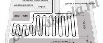
Floor pipe
Installation of a warm water device should not be burdened with the purchase of expensive oxygen protection or any additional layers. The main task should be based on minimizing costs, both for the installation of a water-heated floor and for the installation of individual heated elements. The collector consists of a pipe with a number of splitters. Used to connect circuits. It is recommended to install two splitters at once in the collector cabinet. The first will be responsible for distributing the hot coolant, and the second will be responsible for collecting the cooled coolant.
The essence of the collector
The main feature of a water heated floor is the coolant; the water gradually moves to the heating circuit and gives off part of its energy.
That is why the heating of the floor occurs with the release of heat to the air that is mixed inside the room, and it, as is known, is directed from the bottom up. A number of devices are responsible for supplying warm water to the circuit and intensity:
- the valve is considered the main one;
- a pump must be present;
- collector.
All control of water distribution is carried out using a flow meter. It is this device that plays the main role in the operation of the entire system.
All collectors are designed specifically for hot water, and they are also necessary to collect waste material. In the unit itself, the process of mixing hot water that comes from the source and return takes place.
Thanks to rotameters, there is a chance to ensure that the entire volume of water reaches the floors. Simply put, the equipment will independently control the heat in the water field.
Floor heating cannot do without a rotameter. The design includes a body made of plastic, but there are models made of brass. A float is placed inside any device. There is a flask with a scale.
We recommend: How to install xl pipe underfloor heating?
The float can move up and down and at the same time points to a certain division of the scale. Judging by it, it will be possible to judge the volume of coolant that circulates in the pipeline.
If we talk about theory, the system works without a device, but in this case the adjustment has to be done manually, relying on your own sensations.
The flow meter for the underfloor heating manifold plays an important role; if it is abandoned, the following problems will arise:
- the fact is that in the absence of a flow meter, some floor contours can be supplied with coolants, while the features of the room will not be taken into account;
- the energy consumption used to operate heating devices, for example, either gas or electricity, will be excessively increased.
Let's say you plan to simultaneously heat the bathroom and another room, for example, a bedroom. A gas-powered boiler will heat water for the bathroom and bedroom absolutely identically, that is, there will be one temperature regime.
It is important to install the equipment correctly; to do this, you need to screw the device itself into the collector socket. Fixation occurs due to the nut. When improving a heated floor, it is advisable to try to control the length of the heat pipeline of all circuits, without paying any attention to the configuration. This will simplify the adjustment of the system and it will still be possible to achieve normal temperature parameters.
But we must take into account that the bathroom is small in size, in order to heat it you need less water from the boiler, but more water is required to supply the bedroom. It is possible to compare the heat of each room, but only in this case will you need to use a flow meter.
If you use this device, the temperature will be set in the bathroom and bedroom for a comfortable stay there.
Having carefully assessed the principle of operation of this device, we can draw the following conclusions:
- the device can function completely autonomously, without the need to use any additional power sources;
- the main operating principle of the flow meter makes it possible to sufficiently consume the coolant for the circuit and further significantly reduce the energy costs of all heating devices;
- the design of the entire device is capable of providing control over the amount of water entering the pipes;
- the manifold, which is installed together with the flow meter, makes it much easier to control the operation of the entire system in general. Also, installation of the system is not complicated and does not require special maintenance.
We recommend: How to set up a heated floor?
Recommendations for installing the device
At the design stage, the location where the collector group will be installed should be determined. Most often, it is mounted in a special cabinet, which must be of sufficient size to accommodate all the elements. The equipment is installed at a certain height from the floor near the main pipes.
In this case, you need to place the cabinet so that there is free space for bending the pipes suitable for the manifold. It is desirable that it be placed at the same distance from all heating circuits. If desired, the cabinet can be mounted in a specially made niche or simply attached to the wall.
The figure shows a diagram of the collector assembly. This is how the manufacturer completes the equipment
Assembling a complete manifold for underfloor heating is quite simple. However, before starting work, you should carefully read the instructions, which the manufacturer necessarily includes in the packaging of the equipment. All operations should be performed in strict accordance with its recommendations.
In general terms, assembly is carried out in the following sequence:
- We remove the tubes intended for return and supply coolant from the packaging. They should already be equipped with flow sensors and valves. If the collector is divided into several sections, twist them together.
- We fix the assembled pipes on standard brackets, which will allow you to continue working with greater convenience. The distributor is now a single unit.
- We install shut-off valves, connecting elements, plugs and control devices in place.
- We fix the collector to the wall. You can find recommendations that suggest first installing a valve and a circulation pump. However, in this case it will be very inconvenient to subsequently attach the assembled unit.
- We install a circulation pump and a valve with a servo drive and a thermal head in accordance with the selected scheme.
- We connect the pipes coming from the heating boiler to the unit, and we connect the pipes from the heated floor circuits to the outlets.
The manifold for heated floors is best mounted in a cabinet specially designed for this purpose, which can be “recessed” into the wall or simply mounted on it.
All commissioning work should be carried out before the concrete screed is poured. This is necessary to ensure the tightness of all joints made. We configure the collector.
We check the operation of all control devices that allow you to set the desired floor heating mode, as well as adjust the coolant flows in each circuit.
Purpose of using the collector
A collector is a device with which the coolant flow is distributed over individual circuits of the water floor and then returned back for heating. The collector unit looks like two pipes with holes to which the system circuits are connected.
The presence of a distribution manifold in the heated floor arrangement makes it possible to control the volume of coolant flow. One of the collector pipes is the supply pipe; hot water flows into it and the inputs of the water floor circuits are connected to it.
The return circuits are connected to the return pipe of the collector. The openings to which this connection is made are usually equipped with threaded, fitting or other connections.
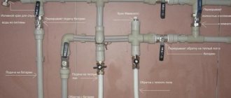
The collector consists of a number of elements such as the collector itself (1 and 2), an adapter for the Mayevsky tap (3); drain valve (4); air vent (5); valve (6); bracket (7); Eurocone (8)
Various devices are also installed here with which you can regulate the coolant flow rates. The simplest version of an industrial manifold is a pipe with a connector called a Eurocone. This is a completely convenient and reliable unit, but it does not allow you to control the flow of water.
To effectively use such a device, you will have to additionally purchase and install a number of elements.
The manifold made in the DPRK is a little more complicated. In addition to the connections at the outlets, valves are installed here; no automatic means of regulating the flow are provided. This is an excellent and inexpensive option for a water floor in a small area with two or three contours of the same length.
Such a system does not require complex management. But on large areas, this type of collector will have to be supplemented with automation.
In addition, the center-to-center distance between the feed and return sections of Chinese devices does not meet the standards adopted in Europe, which can cause problems when connecting it to European-made devices.
Ball valves in such devices are sensitive to low-quality water, and over time they begin to leak. To fix the problem, it is enough to replace the O-rings, but you must take into account the fact that the need for such repairs will arise periodically.
If the operation of the water floor system is intended to be automated, it makes sense to purchase at least a manifold with control valves.
Servo drives can be installed on such valves, connected to thermostats in the rooms. This will ensure automatic control of the coolant flow in accordance with data on the air temperature in a particular room.
To automate the operation of a water heated floor system, flow meters are installed on the collector supply (indicated by a frame), and connectors for servo drives are installed on the return (blue caps at the bottom)
It is most difficult to control a water floor system in which the individual circuits vary markedly in length, but in complex systems this is usually the case. In such a situation, the optimal choice would be a manifold with flow meters installed on the supply, and sockets intended for mounting servos on the return.
Using flow meters, it will be possible to adjust the intensity of the coolant flow, and servo drives in conjunction with thermostats allow you to set the appropriate temperature on each circuit.
If there is no need for automatic control, you can purchase a supply manifold with flow meters, and a return manifold with conventional valve taps.
It happens that it is not possible to choose a collector with the number of connection sockets that corresponds to the project. Then you can take the device “with a reserve”. And the extra holes are simply closed with plugs.
This solution may be useful if you later need to add a couple more loops to the water floor system.
Functions and types of collectors
The function of the collector is to bring the temperature of the water from the heater to the desired level. The design consists of two pipes (supply and return) with outlets for connecting underfloor heating loops.
The hot coolant, under the action of a circulation pump, enters the supply pipe and is distributed among the branches. There the water gives off heat and cools down . After passing through the entire circuit, it is collected in the return line and enters the boiler for heating.
The industry produces collectors in various configurations, with a different set of equipment. directly depends .
Collectors differ in the following characteristics: design, functions performed, materials of elements, installation method:
- The most common type of model is two-valve . One is placed on the supply pipe, the second on the return pipe. Hot and cold water are constantly mixed. These collectors do not experience temperature surges that cause pipeline ruptures.
- A budget option is a pipe with outlets for Eurocones. Used in the home heating system. To use such a simple collector for a heated floor, you will have to purchase additional devices and components.
- Chinese models are efficient and inexpensive. They do not have automation, so they are installed in a small house, where the contours of the heated floor are the same length, and where no automation is supposed to be installed.
Attention! When buying a Chinese manifold, you need to know that the connectors differ from European standards, so modules from European manufacturers are connected through adapters; Chinese ball valves leak and will require replacement of seals.
- Eurocones are expensive models that are completely ready for installation and operation.
- Three-valve combs with servo drives. The peculiarity of the design is that water from the boiler is mixed with cooled media from the return. Used in large premises for special purposes (greenhouses, nurseries).
Important: When mixing water in the collector, a temperature jump may occur.
Collector cabinet
The mixing and distribution point for coolants will not look aesthetically pleasing if it is not hidden in a closet. Its price is low and it’s easier to buy it than to make it yourself if you don’t have the necessary tools. Cabinet designs are most often used built-in, but they can also be external.
Built-in cabinet with manifold
They have holes for fastening. Fixation methods are always described in detail in the instructions
You should pay attention to this when purchasing
It is also important where the piping openings are located in the cabinet and how they fit into the manifold design. All its parts must be freely placed and have access for maintenance and repair.
The cabinet must be securely closed with access to the equipment only to those involved in servicing the system.
All its parts must be freely placed and have access for maintenance and repair. The cabinet must be securely closed so that only those servicing the system can access the equipment.
General characteristics of heated floors
There are several types of heated floors, but the most popular, undoubtedly, is the water system. One of the most important characteristics of this category of systems is that they cannot be connected to centralized heating. Since centralized heating is used to heat apartment buildings, we can draw a simple conclusion - warm floors are not installed in such houses.
In private houses and country cottages there are no restrictions, so you can safely install heated floors in them. They are well suited for any conditions, and if there is a boiler with liquid coolant on the lower floor of the building, then this option will be simply excellent. If installed correctly, a warm floor will provide high-quality and efficient heating of the building.
An important advantage of underfloor heating is its higher efficiency compared to traditional heating systems. The installation of a heated floor is not very complicated and includes several stages, including the installation of a collector. All work can be done with your own hands without any problems.
To easily go through each stage of the work, you need to prepare in advance. The first step is to design the future system, as well as stock up on materials and tools. Next, the base for the floor covering is prepared in those rooms where the heated floor will be installed, and the system itself can be equipped on the finished base. The sequence of work must be considered in detail.
Accessories for water heated floors
The complex design of the mixing unit and collector group is complemented by many auxiliary parts that play one or another role in regulating the operation of warm water floors:
- The thermostatic valve is controlled manually or automatically using an electrothermal drive.
- Hydraulic balancing of the loops of the underfloor heating system occurs through tuning valves (there are options with or without flow meters).
- Ensuring constant pressure is achieved using an overflow valve, which redirects excess liquid to the bypass.
- The radiator balancing shut-off valve is used to open/close the water supply between the collector and the heating system.
- A bypass with a bypass valve, an expansion tank, a safety valve, as well as communicators and controllers are responsible for the trouble-free operation of water-heated floors and continuous monitoring of the operation of the heating system.
The mixing unit may have two or three way mixing valves. The first option is considered more reliable, as it allows you to limit the flow of water directly from the boiler using a balancing valve and thermostatic control units. This protects the circuit from exposure to boiling water, which is especially valuable when using polypropylene pipes.
The 3-way valve design is more versatile in terms of recommended heating area. Unlike two-way units, which cannot serve more than 200 m², a three-way valve creates optimal pressure in heated floors of any size.
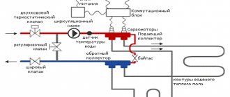
Operating principle and diagram of the water heated floor collector
In the simplest configuration, the collector consists of two tubes with outlet pipes. The first is connected to the boiler, the second to the return. But such a device is not enough for the proper functioning of a heated floor.
In configurations suitable for the system, the mixing unit consists of the main elements :
- tubes connected to the supply and return pipelines;
- circulation pump;
- control unit (valve) with temperature sensor;
- the distribution manifold itself with flow meters.
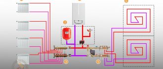
Below is a working diagram of a collector for a warm water floor.
Node purpose:
- The pump maintains water pressure and the speed of its circulation throughout the circuit.
- The valve performs the function of feeding the circuit with hot coolant. The unit is equipped with a temperature sensor, which gives a signal to the valve when the temperature drops below the set value. The valve opens and additional hot water enters the system. The same temperature sensor, upon reaching the desired temperature, gives a signal to stop supply and the valve closes. Thermal sensors are servo drives that maintain the set temperature automatically.
- The comb is designed to connect two or three water circuits. The coolant flow in individual zones is taken into account by flow meters.
Thermostatic valves are installed on each branch of the heating circuits. They are controlled automatically, but have plugs for manual intervention.
As an additional option, flow meters . From them, water flow can be observed visually. The pressure and temperature in the manifold are regulated using a pressure gauge and thermometer.
Materials and tools
The set of materials and tools for arranging a heating system is as follows:
- Boiler;
- Collector;
- Pump;
- Control valve;
- Air vent;
- Valve set;
- Fitting;
- Screws;
- Screwdriver;
- Cement;
- Sand.
This set may vary depending on specific conditions, but the main components are still the same. For example, without a boiler, heating operation is simply impossible, so if it is not installed yet, this will definitely have to be taken care of. Another important element is subsequently attached to the boiler - a pump, which ensures the circulation of coolant throughout the entire circuit.
The valves are designed for installation at the equipment inlet. After installing them, you need to prepare for the long process of installing the distribution pipes. When the pipes are installed, it is the turn of the collector. The design of the collector includes a number of elements that allow you to configure and regulate the temperature regime of the heated floor.
The next item is fittings. You need to purchase the required number of fittings with which the elements of the main line will be connected. In addition, the same fittings can be used to connect the working surface to the main pipeline.
A special item on the list are the pipes from which the working surface of the heated floor will be formed. Typically, glass fiber reinforced polypropylene pipes are used for heated floors. The advantage of such pipes over conventional polypropylene pipes is a much lower coefficient of thermal expansion. You can make a reliable heated floor collector with your own hands from polypropylene, and it will last quite a long time.
However, simple polyethylene pipes can also be a good option - they practically do not expand when heated. The thickness of pipes used for heated floors should be 18-22 mm. In addition, the maximum operating pressure should reach 10 bar and the temperature should be 90 degrees.
Next comes the collector, also called a splitter. This device has taps that allow you to connect various elements of the heating system to it. The design of underfloor heating always includes two collectors - the first is mounted on the supply and supplies the system with heated coolant, and the second collects already cooled water. The design of the manifold itself, in addition to the outlets, includes valves, a device for draining the system, an emergency release valve and an air vent. Before installation, it is necessary to calculate at what height the underfloor heating collector will be most effective and safe.
Assembling the factory manifold
To save on the price of heating equipment and make a collector unit yourself, you need to understand what factory-made products are made of. The kit includes the following parts:
- A distribution element for connecting a supply line to 2 or more outlets, equipped with Eurocones (fittings for connecting pipes). In most cases, it is equipped with transparent flasks, where the coolant flow in each circuit is visible (rotameters).
- The same for connecting to the return line. Instead of flow meters, there are thermostatic valves controlled manually from servo drives or thermal heads of the RTL type. Their operating principle is simple: when you press the spring-loaded rod, the flow area narrows, and the flow of water through the element decreases.
- Automatic air vents installed separately on the supply and return manifolds.
- Taps with plugs for emptying and filling circuits with coolant.
- Thermometers that record the total supply and return temperatures.
- Shut-off ball valves and mounting brackets.
Construction of a collector group for heated floors
For reference. On sale there are manifold units with rotameters on the return line, thermostat valves that regulate the flow. Changing the layout does not affect the operation of the heating circuits.
When purchasing a comb, you can change the complete set depending on your budget and connection diagram to the boiler. For example, buy a distributor without rotameters, install 1 thermometer instead of two, or place the unit in a control cabinet.
Factory kits are manufactured in such a way that the manifold for heated floors can be easily and quickly assembled with your own hands. Judge for yourself: the distribution elements are already assembled, you just need to connect them to the heating circuits and install the auxiliary parts according to the diagram. How to do this correctly, see the following video:
In addition to brass and steel products, there are varieties of combs made from plastic sections, as shown in the photo. Their installation is carried out in the same way, except with more caution when tightening. Please note that the main threaded connections on the groups for draining water and connecting pipes do not need to be packed with flax or FUM tape; rubber seals are provided almost everywhere.
Plastic distributors with installation kit
Manifold cabinet: purpose, types and advantages
Manifold cabinet
The manifold cabinet is a protective structure that protects the mixing unit from outside interference. Essentially, this is a box installed in a horizontal position, equipped with fastening mechanisms and a door.
The use of such a cabinet makes it possible to place the manifold unit in a convenient place without damaging the interior and technical content. Thus, the collector-mixing unit can be placed in any room without fear that children and pets will be interested in the contents.
There are two types of manifold cabinets:
External ones are mounted on the wall surface using special fasteners and legs (if necessary, height adjustments). The outlet slots are covered with removable metal plates. The cabinet itself is coated with powder paint or an anti-corrosion compound on the sides; the door can be white, beige or another color according to the consumer’s taste.
External manifold cabinet
Built-in ones are installed in a niche or covered with clapboard or plasterboard. The side parts, as a rule, are not painted, since they contain fastening and outlet spans. The facade is painted white, but options are also possible.
Built-in manifold cabinet
Both types of structures must have a strong lock and protection against possible thermal burns. Cabinets are not placed below floor level, but are not raised too high. After installing the box, the process of assembling the water floor collector proceeds according to the planned diagram. At the same time, all bends remain easily accessible for laying contours.
You can also place a water supply meter inside the cabinet, combining all the circuits at one point. On the wall, the entire structure will look many times more aesthetically pleasing than a bunch of pipes for the water circuit of a heating system with numerous sensors, valves and taps.
The nuances of installing heated floors without a mixing unit
The main disadvantage of installing a system without a collector is the need to minimize coolant temperature losses along the path “coolant heater – pipeline” and in the system itself. You also need to maintain the required temperature on the floor area. Therefore, it is recommended to take into account the following requirements:
- Insulation of room walls;
- Laying thermal insulation on the floor;
- Availability of high-quality window systems;
- Laying the floor in close proximity to the heating element;
- The area of the room is no more than 20-25 m2.
The main and common mistake when installing such a system without a collector unit is trying to install it on too large an area.
However, some craftsmen argue that in a situation where the “return” will be cold in any case, installing a condensing boiler can save the day. It has high efficiency and such a device is not afraid of low temperatures for heating.
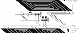
Installation diagram of a heated floor without a mixing unit
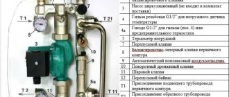
The underfloor heating manifold consists of
- Tee pipes (when purchasing tee pipes, you need to know exactly how many circuits you are going to insulate, how many circuits - so many tee pipes, they can be made of stainless steel or brass - choose those that suit you best);
- A circulation pump pumping water (selected depending on the volume of water that will circulate in the heating system);
- Regulating and supply valves (controlling the supply of additional hot water to maintain the desired temperature);
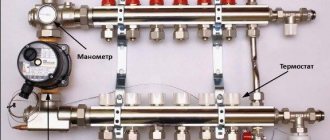
- Pressure gauge (monitoring pressure in the system);
- A thermostat is a special device installed to control temperature; It can measure the temperature of water passing through it (in the case of automated control, and the temperature of the air in the room); signals from the thermostat are sent to a system of valves, which, if necessary, open slightly or, conversely, close, controlling the diameter of the coolant jet entering the system of pipes for heating the premises; thermostats without an automatic temperature control system maintain a constant temperature according to the manual setting.).
- Flow meters (controls the amount of hot water mixed with the return water to achieve a certain temperature in the circuit and the amount of water returning to the boiler for subsequent heating);
- air valve (installed at the end of the system of tubes and serves to release air accumulated in the heating system).
Regulating and supply valves ensure constant mixing of cooled and just heated water from the boiler. They can be three-way or two-way.
Three-way supply valves:
- More often used for rooms with a large floor surface area;
- They can automatically control the supply of hot water to the mixer depending on the ambient temperature, a thermostat is responsible for this;
- When the thermostat signals, it can let hot water into the system with a temperature of about 900C, which will lead to local overheating of a certain section of the pipe.
Two way supply valves:
- Used for premises with an area of no more than 200 m2;
- Mix hot and cold water constantly, regardless of the room temperature;
- To change the temperature of the water entering the circuit pipes, manual control is required
- irovaniya.
Mixing unit structure
The mixing group for heated floors can be built on the basis of a two-way or three-way valve. If the heating system is mixed - with radiators and heated floors, then the unit also contains a circulation pump. Even if the boiler has its own circulation system, it will not be able to “push through” all the loops of the heated floor. That's why they put the second one. And the one on the boiler runs the radiators. In this case, this group is sometimes called a pumping and mixing unit.
Diagram of a three-way valve
A three-way valve is a device that mixes two streams of water. In this case, it is heated supply water and colder water from the return pipeline.
Operating principle of three-way valve
A movable control sector is installed inside this valve, which regulates the intensity of the flow of colder water. This sector can be controlled by a thermostat, manual or electronic thermostat.
The diagram of the mixing unit on a three-way valve is simple: the hot water supply and return are connected to the valve outputs, as well as the output that goes to the supply comb of the manifold for the heated floor. After the three-way valve, a pump is installed that “presses” the water towards the supply comb (the direction is important!). A little further from the pump there is a temperature probe from a thermal head mounted on a three-way valve.
Diagram of a mixing group for a warm water floor on a three-way valve
It all works like this:
- Hot water comes from the boiler. At first, it is passed through the valve without mixing.
- The temperature sensor transmits information to the valve that the water is hot (temperature above the set one). The three-way valve opens the addition of water from the return.
- In this state, the system operates until the water temperature reaches the specified parameters.
- The three-way valve shuts off the cold water supply.
- In this state, the system operates until the water becomes too hot. Then the mixture opens again.
The operating algorithm is simple and understandable. But this scheme has a significant drawback - there is a possibility that in case of failures, hot water will be supplied directly to the heated floor circuits, without mixing. Since pipes in heated floors are laid mainly from polymers, they can collapse if exposed to high temperatures for a long time. Unfortunately, this drawback cannot be eliminated in this scheme.
Please note that in the diagram above the bypass jumper is drawn in green. It is needed in order to exclude the possibility of the boiler operating without consumption. This situation can arise when all shut-off valves on the underfloor heating manifold are closed. That is, a situation will arise when there is no coolant flow at all. In this case, if there is no bypass in the circuit, the boiler may overheat (even overheat for sure) and burn out. If there is a bypass, water from the supply through a jumper (made by a pipe whose diameter is one step smaller than the main one) will be supplied to the boiler inlet. Overheating will not occur, everything will work as normal until flow appears (the temperature in one or more circuits decreases).
Diagram of a two-way valve
A two-way valve is installed on the supply from the boiler. A balancing valve is installed on the jumper between the supply and return pipelines. This device is adjustable, it is adjusted depending on the required supply temperature (usually adjusted with a hex key). It determines the amount of cold water supplied.
A two-way valve must be installed controlled with a temperature sensor. As in the previous scheme, the sensor is placed after the pump, and the pump drives the coolant towards the comb. Only in this case does the intensity of the hot water supply from the boiler change. Accordingly, the temperature of the supplied water at the pump inlet changes (the cold flow is adjusted and stable).
Diagram of a mixing unit based on a two-way valve
As you can see, cold water is always mixed in in this scheme, so in this scheme it is impossible for water to enter the circuits directly from the boiler. That is, the scheme can be called more reliable. But the mixing group on a two-way valve can only provide heating for 150-200 square meters of warm water floors - there are no valves with greater capacity.
Selecting valve parameters
Both two-way and three-way valves are characterized by flow capacity or performance. This is a value that reflects the amount of coolant that it is able to pass through itself per unit of time. Most often expressed in liters per minute (l/min) or cubic meters per hour (m3/hour).
In general, when designing a system, it is necessary to make a calculation - determine the throughput of the heated floor circuits, take into account the hydraulic resistance, etc. But if a manifold for a heated floor is assembled with your own hands, calculations are done extremely rarely. More often they are based on experimental data, and they are as follows:
- valves with a flow rate of up to 2 m3/hour can provide the required area of approximately 50-100 sq.m. warm floor (100 square meters - at a stretch with good insulation).
- if the productivity (sometimes designated as KVS) is from 2 m3/hour to 4 m3/hour, it is fashionable to install them on systems in which the heated floor area is no more than 200 square meters;
- for areas of more than 200 m2, a productivity of more than 4 m3/hour is required, but more often they make two mixing units - this is easier.
The materials from which the valves are made are two-way and three-way - brass and stainless steel. When choosing these elements, you should take only branded and proven ones - the operation of the entire heated floor depends on their performance. There are three clear leaders in quality: Oventrop, Esby, Danfos.
| Name | Connection size | Body/Stem Material | Performance (KVS) | Maximum water temperature | Price |
| Danfoss three-way VMV 15 | 1/2″ inch | brass/stainless steel | 2.5 m3/h | 120°C | 146 € 10690 RUR |
| Danfoss three-way VMV-20 | 3/4″ inch | brass/stainless steel | 4 m3/h | 120°C | 152€ 11127 RUR |
| Danfoss three-way VMV-25 | 1″ inch | brass/stainless steel | 6.5 m3/h | 120°C | 166€ 12152 RUR |
| Esbe three-way VRG 131-15 | 1/2″ inch | brass/composite | 2.5 m3/h | 110°C | 52€ 3806 RUR |
| Esbe three-way VRG 131-20 | 3/4″ inch | brass/composite | 4 m3/h | 110°C | 48€ 3514 RUR |
| Barberi V07M20NAA | 3/4″ inch | brass | 1.6 m3/h | adjustment limit - 20-43°C | 48€ 3514 RUR |
| Barberi V07M25NAA | 1″ inch | brass | 1.6 m3/h | adjustment limit - 20-43°C | 48€ 3514 RUR |
| Barberi 46002000MB | 3/4″ inch | brass | 4 m3/h | 110°C | 31€ 2307rub |
| Barberi 46002500MD | 1″ inch | brass | 8 m3/h | 110°C | 40€ 2984rub |
There is one more parameter that needs to be selected - the limits for adjusting the coolant temperature. The specifications usually indicate the minimum and maximum temperatures. If you live in the Middle Zone or further south, during the off-season, a comfortable room temperature is maintained if the lower control limit is 30°C or less (at 35°C it is already hot). In this case, the adjustment limits may look like this: 30-55°C. For more northern regions or with poor floor insulation, take with an adjustment limit of 35 degrees. When assembled, the mixing group is installed in front of the underfloor heating manifold. Then the coolant at the required temperature enters the circuit.
Installing a manifold for heated floors: advantages
A heating system such as a warm water floor with mixing units has a number of positive aspects.
If you believe the reviews, they are as follows:
- Safe in relation to sanitary standards. Since the heat is distributed over the entire area of the room, this prevents fungus and mold from appearing in certain areas. In addition, such a room will be easier to maintain, since there are no radiators that accumulate dust.
- Do not pose a threat to small children. Since the system is completely hidden, it completely eliminates the possibility of burns.
- This installation is economical compared to other methods of creating heating. The operation is several times more efficient, but at the same time much cheaper.
- Long service life. Provided that the installation was carried out correctly, such a system can operate reliably for more than half a century.
The system will serve you well and for a long time, but when installing it, it is better to contact specialists. Errors that are made during installation are very difficult and expensive to correct, and sometimes impossible.
Results
It is important to ensure that when the water floor heating system is operating, the flow rate on the collector is visible. This is necessary for maintenance. Each water circuit must have its own flow meter.
We recommend: What types of mats are there for heated floors?
As you can see, in the equipment, each element performs its own functions, so each one needs to be given sufficient attention, and in order for the entire system to work as one whole, it is worth equipping it with a flow meter and a collector, which will evenly distribute all the heat.
- Related Posts
- How to set up a heated floor?
- What is included in the Valtek heated floor kit?
- Features of Legrand heated floors
- How to connect a heated floor from a stove?
- How to calculate the power of a heated floor?
- How to install a heated floor sensor?