We take into account the features
To analyze in more detail the connection diagrams for a heated floor with a liquid coolant, let us recall some of the features of this heating system.
- Firstly, the recommended system temperature should be 35-45˚C. Not more. Temperature options in heating radiators are not suitable for heated floors. This means that at the water inlet to the system it is necessary to provide a mechanism for regulating (lowering) the temperature of the coolant.
- Secondly, the coolant circulation in the system must be constant. In this case, the speed of its movement should not exceed 0.1 m per second;
- Thirdly, the difference in coolant temperatures at the inlet and outlet should not exceed 10˚C;
- Fourthly, the water heated floor system should not affect other heating systems, as well as the water supply system of the house.
Separate requirements for gas equipment parameters
Heating using natural resources will have to be chosen correctly. Only in this case it is possible to avoid unnecessary negative emotions, waste of time, and loss of money.
All requirements are established by state standards. Their meaning is strict and unchanging. Linking directly to the area is due to technical capabilities. Which:
- 60 kW. Suitable for 2 meter ceilings. The room has 8 cubic meters of air volume;
- The boiler room is ventilated through three air exchanges. Combustion takes oxygen from a separate source. Kitchen window with window. The air flow is stable in both cases;
- There is a protective layer between the fasteners and the equipment itself. This is usually a sheet of metal. Its role is to prevent fire when the temperature rises during operation;
- the distance to the wall is at least 3 cm. The front side of the boiler allows it to be serviced on one square meter. From the sides, the distance from the unit is at least 60 cm;
- horizontal supply to the chimney no more than 3 meters. The diameter of the pipes used is the same as the heater. It's even better to connect a larger value. Then the hood is tougher.
Essentially, such requirements are checked by the company supplying gas to the house/building. It also allows the connection of such a device to a common highway. In the case of a gas holder, the owners of the premises check themselves. But it is worth remembering that their own lives are at stake.
There are no specific ones indicated for strapping. The gas boiler is connected to the floor heating system and then operates. Ensuring efficient work is compared with comfortable living conditions. An incorrect connection will affect the rest of the house.
The owners themselves are interested in proper connection by checking each parameter. It is better to place all aspects on the plan at the preparatory stage. Then it's easier to check.
We recommend: How to install heated floors on a wooden floor?
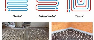
Connection diagrams for water heated floors
Now let's look at practical diagrams for connecting a heated floor in a house.
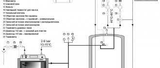
Direct connection from the boiler
This scheme is the easiest to install, but has a number of limitations for implementation.
- Firstly, it can only be used in low-temperature boilers with the ability to regulate the coolant temperature. As a consequence, this scheme can only be used when there is no radiator heating, and the heated floor is the only source of heat in the house.
- Secondly, despite the apparent simplicity of installation, the circuit is “capricious” when it comes to connection nuances and requires experience in such work.
This connection diagram is implemented using 3-way or 2-way valves.
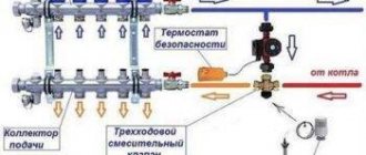
3 way valve
The task of a 3-way valve is to mix hot (direct) and cold (reverse) coolant flows. In the diagram you see an option for installing a 3-way valve. Here it plays the role of a thermostat.
A thermostat is a device that ensures a constant temperature, in our case, the coolant.
This scheme has a number of features. Firstly, it does not work in circuits longer than 35-40 meters. Secondly, it is not suitable if you need to separately regulate the temperature of each circuit.
- The first drawback is eliminated by installing temperature sensors with servo drives and thermostatic valves on each circuit.
- The second drawback is eliminated by installing a circulation pump.
2 way valve
An alternative to the 3-way valve is the 2-way valve or feed valve.
Its task is to provide not a constant, but a periodic addition of water. This mixture is ensured by a thermal head with a temperature sensor included in the valve design. Essentially, a 2-way valve either cuts off hot water from the boiler or adds it to the system.
The advantage of this scheme is its simplicity and the impossibility of overheating. The disadvantage is the 200 meter limitation of the heating area. The limitations in installing circulation pumps with the organization of parallel or sequential (popular) type of mixing are solved.
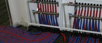
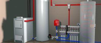
Connection diagram of VTP through a pumping and mixing unit
This circuit is used to simultaneously connect radiators (main heating) and water heated floors (additional heating) to the heating boiler.
To implement this scheme, you will need a collector unit with a pumping and mixing unit. The manifold assembly is sold ready-made and is included in the assembly of the underfloor heating manifold cabinet. The price of the collector unit is 10-20 thousand rubles. Experienced craftsmen assemble the pumping and mixing unit themselves.
The task of the pumping and mixing unit is to provide a high flow rate of the coolant in the system with the possibility of accurate and, most importantly, independent temperature control. Thanks to the pumping and mixing unit, the water-heated floor circuits operate independently from the radiator circuits.
This independence of the circuits ensures guaranteed reliability of operation and quality of connection of the water heated floor system in the house.
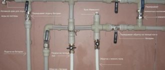
Direct connection of the ETP from the heating radiator
Used to connect one thread of underfloor heating in a small room up to 10 square meters. meters.
Connecting the TP through a thermostatic valve is the simplest and at the same time the most controversial connection method. And that's why.
Firstly, this method only works for very small rooms of no more than 10 square meters. meters. Secondly, this scheme does not provide a high coolant velocity and the temperature difference between the coolant inlet and outlet reaches 40-45˚C, instead of the standard 5-10˚C.
To briefly describe the essence of connecting a heated floor through a thermostatic valve, this is another room heating radiator, only laid in the floor. A loop is made in the radiator heating circuit, a tee is installed, a valve is cut in and an air vent is installed.
Adjustment in such a circuit is made through a thermal head with a sensor (surface or submersible) attached to the heating pipe. There are options for adjusting the air temperature in the room.
Hydraulic separator
This circuit is used in combined heating circuits with radiators. In essence, it is a diagram of the hydraulic separation of a radiator heating system and a warm floor system.
If a circulation pump is used in a radiator heating system, then the presence of a second pump in the mixing unit can lead to a conflicting violation of the hydraulic modes.
To operate two pumps in parallel, a hydraulic separator or heat exchanger is installed in the heating system. Example on the diagram.
Mixer assembly on the pump
This becomes an important element of the entire system. After all, it regulates the throughput and controls the water temperature. Shut-off valves are immediately replaced with thermostatic valves.
We recommend: How to fill a heated floor?
Installation on the general circuit is carried out anywhere. The main thing is that it is located between the inlet and the supply manifold. The third outlet of the water flow carries it further. The return manifold sets its temperature, and cold water dilutes it.
Other elements
The underfloor heating system contains a huge list of various parts and mechanisms. The need for their use is directly related to specific features. This applies to equipment, connection of pipes, coolant, and required heating.
- Related Posts
- What characteristics does Warmstad underfloor heating have?
- How is Lavita underfloor heating installed?
- How is an infrared heated floor installed?
- How to lay a water-heated floor?
- How to design a heated floor?
- What kind of substrate is needed under a laminate for a warm water floor?
How to choose the right three-way valve
The key parameter of any three-way valve is throughput, i.e. the volume of water that the device is capable of passing through itself per unit of time. When choosing a device, you should correlate this parameter with the performance of the boiler.
There is one more nuance to take into account here. Even if the diameter of the valve inlets and outlets seems appropriate in terms of dimensions, this in no way indicates the actual throughput of the device. This parameter is entirely determined by the internal cross-section of the holes, which, depending on the design, are blocked by a ball lock or an adjusting head.
In some models, the dimensions of this hole may be 4 times smaller than the inlet diameter. In order not to make a mistake and not find yourself having to remake an expensive unit, you should carefully study the accompanying documentation before purchasing.
Another important parameter of the device is the cross section. Ideally, the valve should exactly fit the dimensions of the heating system pipes. If an exact match cannot be achieved, you will have to purchase additional adapters.
In addition, it is worth paying attention to the following nuances:
- Be sure to check the availability of accompanying documentation: warranty cards, installation and operating instructions, certificates and licenses.
- When choosing a material, you should give preference to brass or bronze. It is these metals that are best combined with hot liquids and also have a low level of thermal expansion. Products made from non-ferrous metals can be distinguished by their weight - they are much heavier than cheap “stampings” made from powder pressed materials that do not have the proper level of strength.
As for specific models, on the market you can find products from several companies that have long established themselves as reliable manufacturers:
- Esbe . A Swedish company whose products are distinguished by reliability, good performance and attractive appearance. The warranty period is at least 5 years.
- Valtec . A Russian-Italian joint venture producing thermo-mixing valves that combine affordable cost and good technical characteristics. The warranty for the entire range of devices is 7 years.
- Honeywell . An American manufacturer that has prioritized the ease of installation of its products. Three-way valves of this brand have a bright design, high reliability, but no less high cost.
We recommend that you read: Types of ball valves and features of choosing a device