TOP 3 circular pumps for heating.
More and more people are resorting to the use of technological innovations. One of the home improvement tasks when using one is the heating system. The use of a heat supply network of pipelines is now increasingly rare without power equipment, which is based on a circular pump for the heating system. For this purpose, special equipment is produced that pumps water under high pressure and operates at elevated temperatures. There are plenty of models and modifications, and all that remains is to make a choice. But let’s first understand the structure and tasks of the pump.
General information
Pump purpose
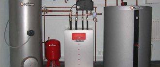
Individual heating systems in a private home are most often organized using plumbing and hot circulating water. Coolant movement is a key factor in the operation of a heating system. To do this, it is necessary to distinguish between a pipeline circuit with forced and natural circulation. In the second case, thanks to the usual laws of physics, the flows of hot water will rotate in the system naturally - the heated water from the boiler will rise up, and after cooling it will fall due to gravity. This principle is suitable if you have a small house, but there is still a risk of pipes freezing.
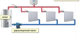
Why is a circular pump needed for heating? It is precisely when there are difficulties in the natural movement of hot water. Such devices are installed in the heating system in the section where the return pipe is located, which connects the radiator equipment and the boiler. With the correct placement of the pump and pipes, you will get a stable heat distribution throughout the house.
Varieties
Two categories of devices should be distinguished, namely models with a “wet” and “dry” rotor. In terms of operating parameters and appearance, they are not much different, but when used, the nuances become more than obvious. So, with a “dry” rotor, the device will vibrate and make a lot of noise, but will be highly productive.
A typical wet rotor device has a power unit that is constantly in the water. This is required for the element base and its lubrication, which will reduce the noise effect, but also reduce the efficiency; in addition, due to the contact of the coolant with the mechanical elements, the quality of the water becomes worse, and this negatively affects the pipes.
Characteristics
Now it’s time to consider the design of a circular pump for heating, as well as the main characteristics by which you can evaluate the performance of the equipment:
- The volume of water that passes through heating equipment in 1 minute. Those who are experts in assessing this parameter recommend equating the power of the equipment to the coolant flow. For example, if the power is 35 kW, then the pump should be selected with a flow rate of 25 liters of water.
- Type of coolant. The heating system can use not only water, but also mixtures, for example, antifreeze additives. This nuance should be thought through in advance, since the materials of the pump design have certain restrictions on use in terms of contact with chemical components.
- Pipe diameter. This is the characteristic that will directly affect the throughput and water consumption. For example, the popular marking of a pump for a heating system is 25/4, and this indicates the diameter in mm and the force of pressure (meters of water column). On average, a 25 mm pipe passes 30 liters of water per minute, provided that the water column is from 4 to 6 meters.
- Ambient temperature. Maximum temperature load at which the pump operates. In modern models this limit is up to 110 degrees.
How to increase the efficiency of an autonomous heating system
Installing a circulation pump is the best way to increase the efficiency of a heating system. Adding a new unit to an existing system is not difficult. The work does not require much time and effort, and the output of thermal energy will increase.
There are three types of coolant circulation:
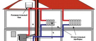
- Natural (gravitational) - the flow of water in the pipes occurs due to the pressure that is created in the system. The boiler is placed below floor level, and the pipes are placed at a slight slope from the boiler to the most distant point of the system. The return pipes are also placed at an angle, but towards the boiler. With this scheme, the circulation of water in the communications slows down as the coolant moves away from the boiler. The water cools down, so the rooms become cold.
- Forced - the coolant is pumped into the pipes under pressure caused by the operation of the circulation pump. The average speed of water movement in the network is 1.5 m/sec. This indicator is sufficient to retain heat as the coolant moves from the boiler to the farthest radiator.
- Combined - the system can operate in two modes.
Pump piping refers to plumbing fixtures installed for the technological insertion of equipment into a common circuit.
The transition from natural coolant circulation to forced or combined circulation is possible when operating any boilers - gas, electric, solid fuel. The type of installation of new equipment will vary - you will need to connect the heating circulation pump.
Forced movement of the coolant is chosen if the boiler equipment does not work during a power outage. In this case, the system stops completely.
Most gas, solid fuel or combination boilers can operate independently of the electrical supply. Therefore, the pump is installed taking into account the possibility of shutting down in case of power failures.
IMPORTANT TO KNOW: Combined circulation is important for systems with solid fuel boilers, because they are almost impossible to turn off instantly. Even if the equipment depends on electricity, the hot coolant will circulate naturally for some time.
TOP 3
Below is a rating of circular pumps for the heating system, which will make it possible to decide on the choice of equipment for use in certain conditions.
Grunfos ALPNA3
This is one of the best options in the segment of units for pumping coolant at the moment. The company is Danish, and it has been developing a line of pumps for heating systems for a long time, but now we are talking about 3-1 generation.
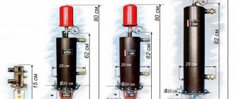
Here, all the developments from Alpha’s predecessors are combined into the best forms and new additions are included. From the basic operating parameters, it can be noted that the pipe has a diameter of 25 mm, the column head is 4 meters and the installation length is approximately 18 cm. But the main thing is that this circular pump can be controlled.
The developers took the issue seriously and created a proprietary smartphone application in which you can control the equipment from a distance. So, you can select the operating mode, diagnostic operations, reading errors, etc. At the same time, there is an emphasis on other equipment, if it is from the same manufacturer, i.e. radiators, closed circulation or underfloor heating system. For security, there is an option to balance the system. Using special sensors, the pump electronics will always monitor the hydraulics and provide adjustment recommendations.
Wester WCP 25-60G
This is the case when the product meets all consumer needs, and at the same time is known only to specialists in this field. This pump is perfect for both single-pipe and two-pipe heating systems. The device operates smoothly, is stable, and can withstand temperatures up to 110 degrees and a pressure of 6 bar. The body is cast iron, therefore it guarantees the reliability and durability of the device.
Users noted that the pump is ergonomic, and also noted such positive aspects as the ability to install equipment both horizontally and vertically, compactness and low noise level.
Belamos VRS 25/4G
This is a budget option from a domestic manufacturer, and you can buy a circular pump for the Belamas heating system for only 2,000 rubles. This unit is universal, but suitable for light loads. The maximum pressure is 4.5 meters, and the productivity is 2.8 m3/hour. But at the same time, users noted that the device is distinguished by high quality work and stably maintains the set temperature. This option is perfect for those who are counting on a certain amount and do not want to overpay.
Circulation pump in the heating system: installation, piping, connection diagram
Source: www.master-forum.ru - official website of the magazines “Tools”, “GardenTools” and “Everything for Construction and Repair” of the “Consumer” series
In the simplest heating system, circulation of the coolant occurs naturally due to the difference in the volumetric weights of the heated and cooled water. Hot water, being lighter, rises through risers and distribution lines. Then it cools down, giving off heat to the batteries, rushes along the return line to the starting point - the heat source, and everything starts all over again.
This scheme is viable if the water pressure is sufficient to overcome all obstacles. Otherwise, the water will cool down before it passes through the entire circuit, and the system, as they say, will “stand up.” To prevent this from happening, a circulation pump is built into the heating system. It not only ensures constant movement of water, but also maintains the pressure necessary for this. Pressure is the pressure difference between the starting and ending points of coolant movement. This is the sum of all friction losses in pipes and overcoming local resistances - radiators, control valves, filters, heat meters.
The second important task of the circulation pump is to save heat and materials. Due to higher speeds of water movement, pumping circuits use pipes of smaller diameters and heating devices with a smaller heating surface. Therefore, there is a one-time saving of materials during installation.
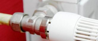
In the future, if each radiator has a thermostat installed (a control valve that ensures a constant temperature in the room), then the pump, controlled by a frequency converter, pumps exactly as much water as needs to be supplied through the thermostats. In this way, by smoothly adjusting the rotor speed, constant energy savings are ensured.
When the thin needle-shaped hole of the thermostat closes when the required temperature is reached, the hydraulic resistance in it increases sharply and, as a result, noise occurs. In this case, the frequency-controlled pump switches to low speed, ensuring low noise characteristics of the heating system.
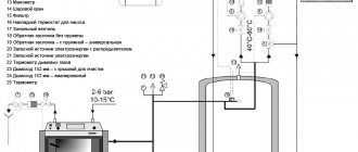
INSTALLATION DIAGRAMS
There are two main options for installing a circulation pump - on the supply line and on the return line. From a hydraulic point of view, there is no fundamental difference where the pump is located. Basically, the circulation pump is mounted on the return line. The first reason - structural - is that rubber flexible inserts are installed before and after the pump. Their purpose is to prevent the transmission of mechanical vibrations from the pump through the transported medium, that is, through water. Flexible inserts can also be used as compensators for thermal expansion of pipelines.
Although the maximum operating temperature for a flexible insert is considered to be 95 °C, there is a dependence of the service life on the temperature of the coolant. At temperatures of 60 degrees or more, this period is sharply reduced.
The second, and main, argument in favor of installing a circulation pump on the return pipeline is the threat of water boiling in the event of a malfunction and airing of the boiler. The pump is not designed for pumping steam; its impeller in this case turns into a powerful resistance to the steam-water mixture. As a result, the circulation stops, while the pressure at the boiler outlet continues to increase and the boiler may explode. This does not apply to modern heating units, which are protected automatically from overheating and boiling.
In addition to purely circulation schemes, there are options for mixing return water into the supply line. For example, if a common boiler is installed in a private house, which should provide water to both the heating system with a maximum temperature of 90 °C and the heated floor circuit with a lower water temperature. In this case, a circulation pump is installed on the return line of the main system. And on the jumper between the supply and return pipelines of the floor heating system there is a separate mixing pump, which directs part of the cooled water from the return line back to the supply, thus reducing the supply temperature. At the same time, the pump also provides circulation in the system.
PUMP UNIT WIRING
The circulation pump is not installed on its own, but in conjunction with the necessary additional equipment, which is commonly called the pump unit piping. Firstly, these are the already mentioned flexible inserts. They are made of polychloroprene rubber. It has high heat resistance, good adhesion to fabrics and metals, resistance to weathering and natural oxidation. When stretched, such rubber crystallizes, due to which the flexible inserts have high strength. For connection to the pipeline, they have cast iron connecting pipes with union nuts and internal threads or steel flanges. With a diameter of 100 mm and more, flexible inserts are equipped with steel control rods that limit their stretching.
As the water moves, a check valve is installed after the pump. Its body can be made of brass, stainless steel or cast iron, the locking element can also be made of various materials. Depending on the method of connection to the pipeline, there are check valves with internal threads (brass body), flanged (cast iron), with external threads and additionally ordered threaded or welded connecting pipes with union nuts, as well as valves clamped between two mating flanges. The last two types come with cast iron and steel bodies. Open check valves have a certain hydraulic resistance, which is calculated when selecting pumps.
Before and after the pump, it is necessary to install a fitting (a short piece of pipe with a diameter of 15 mm) with a three-way valve. A pressure gauge is connected to it to monitor the serviceability and correct operation of the pump. You can install both pressure gauges at once, but usually you make do with one device, moving it between measurement points. It is also useful, with a large pipe diameter and significant dimensions of the pumping unit, to have a drain valve.
The boundary of the pumping unit is ball valves, which allow you to turn off the pump or dismantle the entire unit for repair or replacement.
The diameter of the pump connecting pipes is, as a rule, smaller than the diameter of the pipeline on which it is installed. A common mistake is to select flexible inserts, check valves and even shut-off valves according to the diameter of the pump. According to current standards, the transition must be made near the pump itself, and the entire piping of the pump unit must be taken according to the diameter of the main pipe.
During the heating season, the pump must be constantly running. A pump breakdown turns it into an additional obstacle to water circulation. In severe frosts, in the absence of constant monitoring, pump failure can even lead to defrosting of the system. To avoid this situation, various backup methods have been developed. A simpler and cheaper option is to install a double pump, the so-called monoblock. These pumps are a kind of “Siamese twins”; they have two electric motors connected in parallel in one housing and a common connecting pipeline. A flow-controlled flip cap prevents backflow through a standing pump. Each pump is connected to the power supply separately. Twin pumps are factory set for variable operation. This means that both pumps work alternately. The switch occurs after 24 hours. If a running pump is switched off due to a fault, the second pump is switched on immediately.
Twin pumps can be put into standby mode. Then one of the pumps will work constantly. The second, after certain periods of time (for example, once a day), will be launched for a short time at a low speed to avoid blocking during long periods of inactivity. This is the so-called automatic backup pump test. Simultaneous operation will last only 40 seconds. If the main operating pump turns off due to a breakdown, the backup one will start. One of the pumps can be switched to “Stop” mode, but then their operation will have to be controlled manually.
The disadvantage of a monoblock pump is that only the electric motor is redundant. If the parts responsible for pumping water fail, the pump will still have to be removed, and to do this, turn off the boiler and drain the water. In winter this is not always possible. Therefore, the most reliable method of redundancy is the parallel installation of two single pumps - each with its own flexible inserts, pressure gauges, check valve, bleeder and shut-off valves. The control of such pumps is placed in a separate automation panel.
Along the flow of water, a filter or sump must be installed in front of the pump unit. The general rules for their installation are as follows. The oblique part of the filter is directed along the movement of water, the barrel of the mud trap should be located at the bottom. The filter is installed on a horizontal section or on a descent, the mud collector is installed only on the horizontal. The desired direction of water is shown by an arrow on the body. Even if there are two pumps - the main and the backup - one common filter is installed in front of them. The mesh inside the filter traps mechanical impurities; over time, its holes become clogged with mineral deposits. As a result, the hydraulic resistance of the filter increases. In order to monitor the throughput and temporarily clean the mesh (or the mud tank barrel), a fitting with a three-way valve is also cut into the filter along the flow of water to install a pressure gauge. The second control point in this case is the pressure gauge in front of the pump.
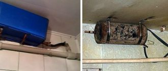
Most modern circulation units have a water-cooled rotor. The water connection can be either horizontal or vertical. However, to prevent the pump from failure, the rotor shaft must be positioned strictly horizontally during installation. Otherwise, air will occur inside the pump, the parts will overheat, and the bearings will remain without lubrication. You also need to pay attention to the arrow marked on the body. It shows the direction of movement of the coolant. A pump installed at a deviation from the horizontal can lose up to a third of its performance. The terminal box should also be at the top.
TECHNICAL RULES FOR INSTALLING PUMPS. ELECTRICAL SAFETY
The operation of the pumps is controlled by signals from differential pressure sensors installed on each pump. The automation system includes temperature sensors - submersible for coolant and external for determining air temperature.
Various pump control modes are used: automatic according to a program specified from the base unit; remote from the base unit; local using buttons installed on the power panel.
It must be remembered that according to current standards, the reliability of the power supply to the pumping unit must meet the requirements of the second category of electricity consumers. The pumping equipment is powered through its own automatic transfer switch panel (ASCHP), which is installed next to the input distribution device of the residential building.
Electric motor control is provided both manually using buttons and automatically from the automation panel, and mode selection is performed by control selectors on the switchboard doors. All electric motors are provided with safety switches.
Metal casings of electrical equipment that are not normally energized must be neutralized; neutral protective conductors are used as neutral conductors. The pump electric motor is grounded in the terminal box, where the neutral wire is connected to the grounding bolt.
The outdoor air sensor is placed out of direct reach on the northern facade, higher than human height and at a distance of at least a meter from the nearest windows. It is advisable to choose a vandal-proof sensor housing.
ADVANTAGES OF PRESSURE CONTROL
When a tenant manually closes the radiator valve or the automatic thermostat reduces the heat supply to the heating device, the amount of water in the remaining parts of the system, that is, in the mains and risers, increases sharply. In a system with an unregulated pump, pressure immediately increases, and therefore noise.
Most modern pumps have the ability to regulate proportional pressure. In practice, this means that when the air temperature rises or falls, the pump changes its rotation speed, thereby reducing or increasing the flow of coolant into the system.
If you install a frequency-controlled pump, the speed of the unit will immediately decrease, electricity consumption will decrease and noise will disappear. That is, when the water flow rate decreases, the excess pressure of the pump is extinguished, and when the coolant flow rate increases, when the flow of water into the heating devices increases, the pressure increases again. This increases the service life of the pump. In addition, frequency converters provide smooth start-up of electric motors and emergency stop of pumps, equalize the input voltage and perform automation functions as part of pumping stations.
Frequency converters are built into the pump, but if necessary, a frequency control station can be purchased separately. This device is programmed by entering commands from buttons, input control is via the monitor. It is better to entrust this work to a professional. The disadvantage of using a frequency converter is the increased cost of pumping equipment.
BYPASS LINE DEVICE
The heating system of a private house, in which a circulation pump is installed, must be protected from the risks of a power outage at the most inopportune moment, when it is frosty outside. In this case, it is advisable to have an uninterruptible power supply that will allow the pump to operate for several hours. But what to do if the batteries are still discharged and there is still no light?
A bypass pipeline around the pump (also called a shunt or bypass) will help solve the problem. He has several tasks. Let's look at them in order.
There are systems in which the diameters of the pipes and the area of the heating devices are designed for the natural circulation of coolant at low negative temperatures. The pump starts working only when the temperature drops to -10 °C, and most of the time the water passes by the pump through the bypass. This is a circulation-pumping circuit.
In systems originally designed for forced circulation, the bypass line allows the pump to be dismantled for repairs without stopping the overall operation of the system. Because even poor circulation is better than none.
Finally, without a bypass, it is impossible to fill the system with water and make up water, because a check valve is installed in the pump piping, which prevents the flow of water through the return pipeline.
The bypass is taken to have a diameter smaller than the return pipeline and is equipped with a shut-off valve. When the pump is running, this valve is closed. When the pump is turned off, the valves in its piping are closed, and the bypass line, on the contrary, is opened.
You can automate the pump-bypass switching if you replace the ball valves with solenoid valves and add a pressure sensor to the circuit. When the pump is turned off, the pressure after it will immediately drop. The sensor will send a pulse to the automation device, and it will open the valve on the bypass, simultaneously closing the pump unit. When the pump returns to operation, the reverse switching will occur. The main thing is that the flow is blocked smoothly, otherwise a water hammer may occur.
CALCULATION OF CIRCULATION PUMP
In a closed system, fluid moves in a closed circle. Provided the system is completely bled and closed, the pump is not affected by static pressure. Therefore, there are only two parameters by which a heating circulation pump is selected - pressure and flow. Pressure is the pressure that must be developed to overcome existing resistance. It is measured in different ways - in pascals, meters of water, atmospheres, bars - all these units are mutually convertible. Denoted by the letter H - this is the conditional “suction height” of the pump.
In order for the coolant to reach the most remote points of the system, the pump pressure must exceed the sum of all hydraulic losses. The first term is the required pressure. It consists of the resistance of pipes, heating devices and control valves. The second term is the losses in the pump piping. This is the resistance of the filter, check valve, and, if available, also the heat meter and control valves. The third is free pressure, which is taken to be equal to two to three meters of water column. In total, these values give the calculated pump pressure.
Pump flow is the volume of water that it must pump. Flow is usually designated as G and is measured in tons per hour or cubic meters per hour. To determine the flow or, as they also say, pump flow, you need to know the thermal power of the system - the amount of heat that the boiler produces. It is designated by the letter Q. The pump flow is the thermal power divided by the temperature difference between the supply and return coolant, that is
G = "(Q)/(T1 - "T2), m3/h, Q - in kilowatts (T1 - T2) - in degrees Celsius
The supply water temperature is usually 85–95 °C, the return water temperature is 60–70 °C.
After the pressure and flow have been determined, the selection of a specific pump is carried out according to nomograms that show the working area of this particular unit. The abscissa axis is feed, the ordinate axis is pressure. You can't go wrong when choosing. A pump that is more powerful than necessary will cause noise, waste energy, and will quickly fail. If there is insufficient power, circulation throughout the entire circuit will not be ensured.
It must be remembered that operating the pump at a minimum flow below the working area will cause overheating and stop the pump. But you can’t strive for the maximum point either - the pump works best with an efficiency of about 80%.
It is advisable to make calculations in two versions - for winter with maximum water temperature and for the transition period. The pump must perform equally well under all conditions. Installing a frequency converter will further help this.
“WET” AND “DRY” ROTOR
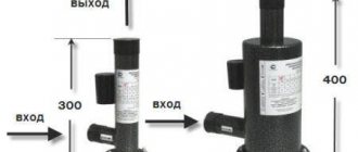
The main elements of the pump, in addition to the electric motor, are a rotor and a shaft with an impeller, the blades of which, when rotating, create the necessary coolant pressure in the pipes. A vacuum is created on the suction side, due to which water rushes into the pump, and at the outlet of the pump, the impeller pumps coolant into the space limited by the pipe walls, and the pressure necessary for circulation develops.
Based on the cooling method, pumps are divided into two types. Submersible or “wet” pumps are so called because their rotor and impeller are immersed in the coolant. Pumps with a “wet” rotor are low-noise - water muffles the sound of rotating parts. They do not require constant maintenance for lubrication and replacement of gaskets - this function is also performed by the coolant. Such pumps are small in size and economical in electricity consumption. At the same time, they have the ability to quickly and flexibly adapt to changing working conditions. In small heating systems of private houses they have proven themselves to be the best.
Pumps of this design do not have a fan, rolling bearings or shaft coupling. These parts are three of the four noise sources of any pumping unit. The fourth source of noise from a pump is the noise of water flowing through its hydraulic part. At flow rates for which pumps with a “wet” rotor are produced (up to 70 m3/h), the noise of water flowing through the pump is extremely low. In the engine power range from 20 W to 1 kW, the sound pressure level is only from 22 to 45 dB. For comparison: the permissible sound level in a residential apartment during the day is 40 dB, at night - 30.
The disadvantage of “wet rotary” pumps is their relatively low efficiency - approximately 50%. This is due to the fact that the stator (the stationary part of the engine) of a “wet” pump is isolated from the rotor by a metal cup - a sleeve, and there is no way to completely and reliably seal this connection.
The rotors of “wet” pumps are made of stainless steel or wear-resistant plastic, the impeller is made of ceramics, carbon agglomerate or stainless steel. Based on operating experience, such pumps have been operating for twenty years or more without major repairs. Of course, increased demands are placed on water quality when installing a “wet” pump. At a minimum, there should be both fine and coarse filters, and not just a simple mud filter.
Initially, wet rotor pumps were recommended for installation only in the return pipeline. Now the materials from which parts in contact with water are made make it possible to install such pumps on the supply side.
Pumps with a “wet” rotor do not require the installation of flexible inserts before or after them.
In “dry” circulation pumps, the rotor is only partially immersed in liquid, and the motor is isolated from the working shaft by polished steel rings. When the pump starts, these rings begin to rotate, a water film forms between them, sealing the connection due to the difference in pressure in the heating system and the external atmosphere. The efficiency of pumps with a dry rotor reaches 80%. However, these pumps are so noisy that according to current regulations they cannot be located adjacent to living rooms.
The sealing elements of a “dry” pump must be lubricated regularly, otherwise the mechanical seal will be destroyed and dust particles will get inside the housing, which are intensively attracted by the rotating rotor. Accumulating on the rings, dust can damage them and lead to depressurization of the pump.
Before and after a pump with a dry rotor, it is recommended to install flexible inserts to eliminate the transmission of vibrations and noise.
Currently, leading pumping equipment companies are practically not inferior to each other in their main positions. The difference is small - perhaps the average retail prices of one company are slightly lower, but at the same time the after-sales service of the other is more developed and the energy consumption of the engines of the third is slightly lower. Owners of pumps of any well-known brand turn to service for the first time only after ten to fifteen years of continuous operation of the equipment.
Exploitation
To install a circular heating pump, it should be installed in the circuit by cutting into a pipeline with pre-installed shut-off valves on the water source side. The system must be filled with water before use. At that time, the minimum pressure value must be set on the pipeline line. After this, you can connect the system with the network and the required cable insulation, and the equipment will turn on.
In the future, as described in the technical instructions, such pumps should be constantly checked for air contamination. If modern models are used, then automation will do this.
In other cases, everything is done mechanically. Deaeration should be carried out through the pump, slightly opening the exhaust valve at the highest point of the unit. Some other models have a special air vent. In this case, there is no need to try to remove air from the entire system, since this is difficult from a technical point of view.
Repair and maintenance
The device requires periodic maintenance (approximately once every 3 months), and for this you only need to perform a routine check of the design, the integrity of the connections and cables. Automation should also be under control. As for repairs, it will be more difficult to carry out it at home, although certain elements can be replaced without involving a specialist, but restoring the structural integrity or repairing the rotor goes beyond the scope of home repairs and the work should be left to a knowledgeable person. If a malfunction of the electrical internal contacts is detected or “dry” running is observed, it may be necessary not to partially, but completely replace the pump.