Why do you need a comb?
What makes up the functionality and efficiency of a heating system? It should provide a comfortable temperature in all rooms of the house and the necessary heating of water. In addition, it must be safe during operation and as repairable as possible.
One of the functions of the comb is the ability to turn off the supply of coolant to a separate circuit of the heating system. This allows you to carry out repair work without turning off the heating as a whole.
All these conditions of normal operation are helped to solve by the functional element of the collector (radial) heating distribution circuit, which is called a collector or comb. Let’s say that suddenly, as happens most often, a radiator or pipe joints leak in a house. If you have a comb, you can solve this local problem without turning off all the heating. It is enough to simply shut off the required valve and turn off only the area that needs repair.
In addition, one collector, which is installed on the entire heating system of the cottage, will do an excellent job of controlling the heating process. He will also be able to regulate the temperature in each room of the house. Using this device allows you to control the heating system quite efficiently and simply. At the same time, the costs of effort and resources are reduced to a minimum.
Both distributor and regulator
At its core, a distribution comb is a centralized unit that allows the coolant to be distributed to its destination points. In a heating system, it performs no less important function than a circulation pump or the same boiler. It distributes heated water through the mains and regulates the temperature.
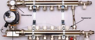
This diagram shows the general operating principle of a collector block consisting of two combs: through one, coolant is supplied to the system, and through the second it is returned
This unit can be called a temporary coolant storage tank. It can be compared to a barrel filled with water, from which the liquid flows not through one hole, but through several. In this case, the pressure of water flowing out of all holes is the same. This ability to simultaneously ensure uniform distribution of heated liquid is the basic principle of operation of the device.
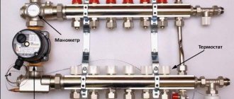
Externally, the collector looks like an assembly of two combs, most often made of stainless steel or ferrous metal. The terminals available in it are intended for connecting heating devices to it. The number of such outputs must correspond to the number of heating devices served. If the number of these devices increases, the unit can be expanded, so the device can be considered dimensionless.
In addition to the leads, each comb is equipped with locking mechanisms. These can be two types of taps installed at the outlet:
- Cutting off. Such taps make it possible to completely stop the supply of coolant from the general system to its individual circuits.
- Regulatory. With the help of these taps, the volume of water supplied to the circuits can be reduced or increased.
The manifold includes valves for draining water and releasing air. It is also most convenient to place measuring equipment in the form of heat control meters here. In this case, everything that is necessary for the effective operation of this node will be in one place.
Why are there two combs in the manifold block? One serves to supply coolant to the circuits, and the second is responsible for collecting already cooled water (return) from the same circuits. All elements necessary for effective operation must be on each of the combs.
Calculation of comb diameter for heated floors
To ensure balance and stability, all elements of the heating system must match each other in their throughput, which depends on the cross-section of the pipes. The basic principle by which the heating manifold should be calculated states: the distribution hydrocollector must have a cross-sectional area of the body equal to or greater than the total cross-sectional area of all outlet branches, and the cross-sectional area of the collection comb must not be less than the sum of the areas of the supply pipelines.
Failure to comply with this requirement when designing the collector will lead to insufficient coolant supply, which will greatly reduce the quality of heating.
In the form of a formula, the area rule will look like this:
where S0 is the cross-sectional area of the comb,
S1-Sn – cross-sectional areas of outgoing branches.
Pipelines entering the hydraulic collector are not taken into account.
This formula can be brought into a more understandable form by remembering the school geometry course. The cross section is calculated using the formula S = π * r², but for simplicity and convenience, it is better to calculate the collector through the diameter: S = π * d 2 /4. Following this formula, the original equality is transformed into the following construction:
π * d0 2 /4 = π * d1 2 /4 + π * d2 2 /4 + π * d3 2 /4 + π * dn 2 /4,
where d0 denotes the diameter of the comb,
d1-dn – internal dimensions of outflow branches.
By reducing the number Pi and putting everything under the square root sign, you can significantly simplify the calculations:
This results in a universal formula suitable for calculating a hydraulic collector of any complexity and configuration. If all outgoing heating branches are of the same size, the equality is simplified even more:
where N denotes the number of branches extending from the comb.
In addition to the size of the collector pipes, you also need to take into account the distances between them. Thus, the distance between the input and output groups of branches should be equal to six diameters, and the branches of the heating circuits should be three sizes apart from each other.
Disassembling the diagram for calculating the diameter of the comb is not enough to assemble an effective hydraulic collector. You also need to understand what diameter the pipes should be so that the balance of the system is maintained. The selection of pipes is based on their internal diameter, on which the cross-sectional area and throughput depend, that is, the amount of water that can pass through the heating system per unit of time.
It is believed that to ensure a comfortable temperature, the branches extending from the collector must give off 1 kW of heat for every 10 m 2 of the room. Usually they provide a 20% reserve in case of excessive frost, that is, you need 1.2 kW for every 10 m. Considering that the optimal speed of the coolant is 0.4-0.7 m/s, and its temperature is 80 degrees, for the room with an area of 20 m2, pipes with a cross section of about 10 mm are needed. The flow rate of water leaving the hydrocollector will be 110 l/hour.
The calculation of all these figures is carried out using a complex formula, which is easier to replace with a table. Using the table, you can easily correlate the size of the room with the required size of pipelines, knowing the required thermal power of the system.
The simplified calculation scheme looks like this: D = √354∙(0.86∙Q:Δt):V, where:
- D – pipe diameter in centimeters;
- Q – heating thermal power in kilowatts (1.2 kW for every 10 m2);
- Δt – temperature difference between the supply from the comb (80 degrees) and the return (usually 65-70 degrees);
- V – water speed in m/s (0.4-0.7 m/s with the optimal option).
Separately, it is worth noting the required power of the pump unit installed in the hydraulic manifold. It forces water to circulate within the heating system. It is based on the throughput coefficient, which, in turn, depends on the water flow and the diameter of the pipes and is measured in m 3 / h.
To make the reservoir calculation formula more clear and understandable, it is worth considering an approximate situation. Let's say there is a house with an area of 100 square meters. m., in which two heating circuits and one water heating circuit for domestic use are installed. Accordingly, the hydraulic collector will include three branches. It is necessary to calculate the required size of the comb so that there is enough hot water for all circuits of the system.
The internal diameter of the collector pipes can be found out from tables of correspondence between diameters and the materials from which they are made, or you can calculate it yourself using a simple ruler. For example, let's take the size to be 20 mm. All three pipes of the system will be the same. You need to substitute the number 20 into the formula derived earlier, and then you get:
d0 = 2 * √(20 2 /4 * 3) = 2 * √300 ≈ 36 mm
Important! Please note that if, after extracting the root, a fractional number is obtained, it should be rounded up so that the size of the comb is sure to fit.
In the example shown, the internal diameter of the manifold must be at least 36 mm. You can select the required material for the pipe that forms the hydraulic collector from the same tables, or by consulting in hardware stores.
One of the best ways to ensure a comfortable temperature in a house or apartment is to install a heated floor system. This system itself consists of many elements, each of which is integral and important. But a special place among them is occupied by the distribution comb, also known as the underfloor heating manifold. Without it, the system cannot function normally and provide its owners with high-quality and comfortable heating of residential premises. Let's look at what a comb for a heated floor is, how it is designed and by what principles it works.
Comb for heated floors
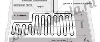
The story about the distribution comb should begin with the role of this unit in a warm floor and with an explanation of why it would be impossible to ensure normal operation of the system without it. You can see a simplified diagram of such heating in the image below. The coolant, which is ordinary water, comes from the boiler (or a centralized heating main, if we are talking about a city apartment) to the collector unit, where it is mixed with the liquid that circulated in the system previously. Then the water flows along the contours laid under the floors and gives off its heat to them.
Simplified diagram of a heated floor system
As a rule, the real scheme of a heated floor is more complex than the one in the image above - there are several contours, and they have different lengths of pipes. Accordingly, they need different amounts of coolant. But if hot water comes from a source in the form of a boiler or main without any distribution, then most of it (water) will rush into the smallest circuit. As a result, there will be overheating. Conversely, on large circuits there will be a lack of heat.
A diagram illustrating the location of underfloor heating circuits in various rooms of the house. You can see that they differ greatly in their area and the location of the supply and discharge lines
Important! The presence of a correctly adjusted comb solves this problem - the water flow in each individual section of the heated floor is set in accordance with the need for coolant. At the same time, both a small bathroom and a large living room will be heated equally well.
The comb for heated floors has another function - reducing the water temperature to a level acceptable for the circuits. The coolant from both the boiler and the central line is supplied very hot, about +70-80 or even more degrees - making the temperature lower is unprofitable in terms of fuel consumption. But such a liquid is not suitable for heated floors. This means that it must be cooled by mixing it with already cooled water from the “return” of the heating circuits. This happens inside the underfloor heating comb. Using sensors and valves connected to them, the manifold maintains the temperature at a certain level set by the user of the system.
Distribution comb (collector) for warm water floor
A comb for heated floors can be divided into the following components:
- supply manifold;
- return manifold;
- fasteners for assembly and installation;
- shut-off valves for supply and return from the boiler;
- thermometer;
- drain tap;
- a device for releasing air from the system (also known as a Mayevsky valve);
- mixing manifolds for supply and return;
- pump;
- valve for supplying coolant from the boiler to the comb.
Comb device for heated floors
Now let's look at them separately. The supply manifold is a horizontal pipe with several branches - two or more. From it the coolant flows into the heated floor circuits. The supply manifold is equipped with flow meters - devices that help regulate the volume of water entering a particular element of the system. To do this, the flow meter changes the cross-section at the branch from the collector to the circuit.
The “return” collector is similar in appearance - it is also a horizontal pipe with branches. But here, instead of flow meters, thermostatic valves, also known as thermal heads, are installed. With their help, the user can regulate the temperature in individual areas of the heated floor.
Both collectors are secured with two mounting brackets . They, in turn, are attached to the wall at the location where the comb for the heated floor is installed.
The supply circuit (bottom) and return circuit (top) are together, assembled and fixed on mounting brackets
Shut-off valves are used to completely shut off the supply and return lines going to the heated floor comb from the heating boiler or centralized main.
Important! When installing such a heating system, place a bypass in front of the comb and shut-off valves. Without it, when the supply to the underfloor heating manifold is cut off, there is a risk of overheating and failure of the boiler.
A thermometer is necessary to monitor the temperature in the manifold system for underfloor heating. The drain valve is used to discharge water for the purpose of repair and maintenance of the unit. And the Mayevsky valve is required to bleed air from the underfloor heating pipelines - if it (air) is present, the liquid may stand up in one of the circuits and the heating efficiency will sharply decrease.
The coolant in such a heating system cannot move properly on its own, so a pump . And finally, the comb is complemented by various fittings, angles and tees, connecting all the elements into a single product and ensuring the movement of water from the boiler to the supply manifold and from the outlet to the “return”.
Pumping and mixing unit for heated floors
To maintain the temperature in the heated floor at the proper level, you need to add a little very hot water from the boiler or centralized line to the circulating coolant. For this purpose, a supply valve is built into the comb, which can be two- or three-way. You can learn about the principles of their operation in the subsections below.
Why are distribution manifolds needed for water heated floors?
A two-way valve is installed in the system directly in front of the heated floor comb. At the same time, it is equipped with a remote temperature sensor, which, as a rule, is located next to the “return” manifold. The valve has two states (open and closed), which are determined by the position of the rod, which, in turn, is controlled by the thermal head.
The principle of operation of such a system is as follows: first, the two-way valve is open, liquid from the boiler with a high temperature enters the comb. There, already cooled water from the “return” is mixed with the liquid and this mixture is sent to the supply manifold. In this case, a remote sensor measures its temperature. If it is still below the set value, the two-way valve remains open. If the water warms up to a certain temperature or even exceeds it, the device closes and the flow of coolant from the boiler stops. The liquid in the underfloor heating system circulates independently.
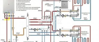
Detailed wiring diagram for a heated floor boiler (with a two-way valve)
But over time, giving off heat to the room, it will cool to a temperature that is lower than normal. In this case, the thermal head of the valve, taking into account the data from the sensor, will raise the rod - the valve will open, and very hot water from the boiler will again be mixed with the liquid in the comb. The balancing valve shown in the image below is necessary to regulate the volume of “return” that will be mixed with the coolant.
A two-way valve is a fairly reliable system in which the likelihood of the locking element breaking and excessively hot water entering the heated floor is minimized by the presence of a thermostat and the very principle of operation of the device. But at the same time, the accuracy and smoothness of regulation are inferior to the scheme with a three-way valve.
Mixing unit with two-way valve
Important! It is also worth saying that a comb with a two-way valve has a limitation in area - it can heat no more than 150-200 m2 of residential premises. As a rule, the device’s performance is not enough for more.
Distribution manifold for heated floors
Now let's look at the operating principle of this unit with a three-way valve. As can be understood from the name, this control device has not two, but three inputs - the supply from the boiler is connected to one, the outgoing collector is connected to the second, the line from the return collector with already cooled water is connected to the third. For better clarity, we will present the work process step by step.
Connection diagram with three-way valve
Step 1. Initial position, on the three-way valve the mixing line is completely closed and the supply from the boiler is open. Hot coolant enters the comb.
Step 2. The sensor located in the comb gives a signal when the temperature is exceeded. The valve shut-off element moves, partially opening the mixing line and closing the supply line. The already cooled liquid from the return line of the heated floor is added to the hot water from the boiler. And the more the coolant temperature is higher than normal, the more the supply from the boiler will be shut off and the mixing line will be open.
Step 3. The coolant temperature has returned to normal, the shut-off element of the three-way valve remains in its current position.
Step 4. The coolant temperature drops after several cycles of passage through the circuits. Information about this is received by the valve from the sensor, the shut-off element closes the mixing line and completely opens the supply of hot water from the boiler. The cycle repeated.
Three-way mixing valve and its position on the diagram for connecting the comb to the boiler
A more visual representation of the connection diagram for a three-way valve between the boiler and the underfloor heating comb
A simplified diagram of how the coolant supply in a three-way valve is regulated and how colder water is mixed into it
According to this principle, the three-way valve constantly regulates the temperature of the coolant, and mixing is carried out not directly in the comb, as in the previous scheme, but in front of it, in the valve itself.
Such a system has the best indicators of smoothness and accuracy of regulation. In addition, it can effectively “cook” water for heated floors with an area of 150 m2 or more. But at the same time, a three-way valve is less reliable than a two-way valve - there is a risk that the control element will fail. And if it remains in a position in which the supply of very hot water from the boiler is constantly open, then damage to the underfloor heating pipelines is possible.
Photo of a warm water floor comb
Separately, it is worth mentioning how to choose the right comb for a heated floor. In this case, you should pay attention to the following criteria:
- the material from which the supply and return manifolds are made;
- the number of circuits on the manifolds in the comb, the permissible level of pressure and water flow;
- degree of automation of the product - what sensors are present in the comb, are there thermostats and other electronics for fine-tuning the temperature in the heated floor circuits;
- manufacturer of combs for heated floors.
Choosing a comb for heated floors
Now we will reveal each of the points in more detail. Let's start with the material from which the comb is made.
Table. Materials used in the production of combs for heated floors.
How to assemble a heated floor comb
It must be said that assembling a comb with your own hands is a very real task. If you installed the heating system in your home yourself, then you have enough skills to assemble this unit. Moreover, factory-made combs are supplied complete and are accompanied by installation instructions with diagrams and explanations. An example of such a diagram is presented below:
At the moment, distribution units are made of the following materials:
- brass;
- stainless steel;
- plastic (polyamide).
A factory-made plastic comb is truly a godsend; its cost is much lower than that of its metal “brothers.” Moreover, in practice it functions no worse; in any case, there are very few negative reviews about it. Assembling a distributor from any material consists of connecting the sections of the comb to each other, screwing a mixing unit from a pump with a valve to them, installing thermometers, taps and air vents. The finished collector can be installed in place and pipes connected to it.
For those who do not want or cannot purchase a plastic manifold, there is another option - to independently solder a comb from polypropylene pipes and fittings. To do this, you need to stock up on the required number of tees and sections of PPR pipes of the same diameter. Since tees cannot be connected directly to each other, pipe blanks should be cut to serve as connecting nipples.
If you have managed to solder the required number of tees, all that remains is to securely attach them to the wall, and then fit the rest of the piping around them: pump, valve, taps and other parts. We must try to ensure that the massive parts are attached to the wall independently, and do not load the distributor with their weight. True, a self-made comb will be devoid of flow meters and control valves, but if necessary, they can be purchased and installed additionally.
How the comb assembly for heated floors works
A comb for heated floors can be divided into the following components:
- supply manifold;
- return manifold;
- fasteners for assembly and installation;
- shut-off valves for supply and return from the boiler;
- thermometer;
- drain tap;
- a device for releasing air from the system (also known as a Mayevsky valve);
- mixing manifolds for supply and return;
- pump;
- valve for supplying coolant from the boiler to the comb.
Comb device for heated floors
Now let's look at them separately. The supply manifold is a horizontal pipe with several branches - two or more. From it the coolant flows into the heated floor circuits. The supply manifold is equipped with flow meters - devices that help regulate the volume of water entering a particular element of the system. To do this, the flow meter changes the cross-section at the branch from the collector to the circuit.
Feed manifold
The “return” collector is similar in appearance - it is also a horizontal pipe with branches. But here, instead of flow meters, thermostatic valves, also known as thermal heads, are installed. With their help, the user can regulate the temperature in individual areas of the heated floor.
Return collector
Both collectors are secured with two mounting brackets . They, in turn, are attached to the wall at the location where the comb for the heated floor is installed.
The supply circuit (bottom) and return circuit (top) are together, assembled and fixed on mounting brackets
Shut-off valves are used to completely shut off the supply and return lines going to the heated floor comb from the heating boiler or centralized main.
Important! When installing such a heating system, place a bypass in front of the comb and shut-off valves. Without it, when the supply to the underfloor heating manifold is cut off, there is a risk of overheating and failure of the boiler.
Ball valve
A thermometer is necessary to monitor the temperature in the manifold system for underfloor heating. The drain valve is used to discharge water for the purpose of repair and maintenance of the unit. And the Mayevsky valve is required to bleed air from the underfloor heating pipelines - if it (air) is present, the liquid may stand up in one of the circuits and the heating efficiency will sharply decrease.
The coolant in such a heating system cannot move properly on its own, so a pump . And finally, the comb is complemented by various fittings, angles and tees, connecting all the elements into a single product and ensuring the movement of water from the boiler to the supply manifold and from the outlet to the “return”.
Pumping and mixing unit for heated floors
To maintain the temperature in the heated floor at the proper level, you need to add a little very hot water from the boiler or centralized line to the circulating coolant. For this purpose, a supply valve is built into the comb, which can be two- or three-way. You can learn about the principles of their operation in the subsections below.
Why are distribution manifolds needed for water heated floors?
Operating principle of a heated floor comb with a two-way valve
A two-way valve is installed in the system directly in front of the heated floor comb. At the same time, it is equipped with a remote temperature sensor, which, as a rule, is located next to the “return” manifold. The valve has two states (open and closed), which are determined by the position of the rod, which, in turn, is controlled by the thermal head.
The principle of operation of such a system is as follows: first, the two-way valve is open, liquid from the boiler with a high temperature enters the comb. There, already cooled water from the “return” is mixed with the liquid and this mixture is sent to the supply manifold. In this case, a remote sensor measures its temperature. If it is still below the set value, the two-way valve remains open. If the water warms up to a certain temperature or even exceeds it, the device closes and the flow of coolant from the boiler stops. The liquid in the underfloor heating system circulates independently.
Detailed wiring diagram for a heated floor boiler (with a two-way valve)
But over time, giving off heat to the room, it will cool to a temperature that is lower than normal. In this case, the thermal head of the valve, taking into account the data from the sensor, will raise the rod - the valve will open, and very hot water from the boiler will again be mixed with the liquid in the comb. The balancing valve shown in the image below is necessary to regulate the volume of “return” that will be mixed with the coolant.
A two-way valve is a fairly reliable system in which the likelihood of the locking element breaking and excessively hot water entering the heated floor is minimized by the presence of a thermostat and the very principle of operation of the device. But at the same time, the accuracy and smoothness of regulation are inferior to the scheme with a three-way valve.
Mixing unit with two-way valve
Important! It is also worth saying that a comb with a two-way valve has a limitation in area - it can heat no more than 150-200 m2 of residential premises. As a rule, the device’s performance is not enough for more.
Distribution manifold for heated floors
Operating principle of a heated floor comb with a three-way valve
Now let's look at the operating principle of this unit with a three-way valve. As can be understood from the name, this control device has not two, but three inputs - the supply from the boiler is connected to one, the outgoing collector is connected to the second, the line from the return collector with already cooled water is connected to the third. For better clarity, we will present the work process step by step.
Connection diagram with three-way valve
Step 1. Initial position, on the three-way valve the mixing line is completely closed and the supply from the boiler is open. Hot coolant enters the comb.
Step 2. The sensor located in the comb gives a signal when the temperature is exceeded. The valve shut-off element moves, partially opening the mixing line and closing the supply line. The already cooled liquid from the return line of the heated floor is added to the hot water from the boiler. And the more the coolant temperature is higher than normal, the more the supply from the boiler will be shut off and the mixing line will be open.
Step 3. The coolant temperature has returned to normal, the shut-off element of the three-way valve remains in its current position.
Step 4. The coolant temperature drops after several cycles of passage through the circuits. Information about this is received by the valve from the sensor, the shut-off element closes the mixing line and completely opens the supply of hot water from the boiler. The cycle repeated.
Three-way mixing valve and its position on the diagram for connecting the comb to the boiler
A more visual representation of the connection diagram for a three-way valve between the boiler and the underfloor heating comb
A simplified diagram of how the coolant supply in a three-way valve is regulated and how colder water is mixed into it
According to this principle, the three-way valve constantly regulates the temperature of the coolant, and mixing is carried out not directly in the comb, as in the previous scheme, but in front of it, in the valve itself.
Such a system has the best indicators of smoothness and accuracy of regulation. In addition, it can effectively “cook” water for heated floors with an area of 150 m2 or more. But at the same time, a three-way valve is less reliable than a two-way valve - there is a risk that the control element will fail. And if it remains in a position in which the supply of very hot water from the boiler is constantly open, then damage to the underfloor heating pipelines is possible.
Photo of a warm water floor comb
How to install correctly
The installation of the collector is carried out depending on the location of the boiler main pipes, as well as on the configuration of the pipelines for each individual room. As a rule, the installation site is chosen to be a point equidistant from each end of the pipeline to the longest.
If it is intended to heat a sufficiently large number of adjacent rooms, then it is more expedient to provide in advance for the presence and location of several coolant separation units. Compliance with this condition will ensure optimal hydraulic operation of the entire system.
Manifold cabinet
Most often, collectors with two outlets are used, but in some cases it is necessary to install mixing units with four or more, up to twelve units. In this case, the entire structure is quite large in size, so it is very often “hidden” in a manifold cabinet, which is specially equipped for this with your own hands. It is a metal box in which the collector itself and all its components are placed (pump, mixing units, loop terminals, etc.)
It can be closed or open type. Also both built-in and wall-mounted. The first ones have a front side decorated to match the overall interior. And the latter, in most cases, have a printed powder coating.
The dimensions of the cabinet directly depend on the size of the collector, taking into account all additional elements. The optimal mounting height is about half a meter from the floor. It is not entirely rational to mount the cabinet below, since subsequently it will not be entirely convenient to insert the pipes into the manifold itself.
In addition to functional advantages, such an installation will add aesthetics to the interior of the room, and will also subsequently protect the rather expensive installation from accidental and unwanted mechanical damage.
Basement
When it is planned to use a collector simultaneously on two floors of a house that has a basement, then most often the location of the comb is determined exactly there.
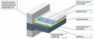
Design and principle of operation
In the process of laying out the pipes of the heating circuits, their ends from all rooms converge in one place, where the heated floor comb is connected to them. It is a distribution and mixing unit whose task is:
- reduce the temperature of the coolant supplied from the boiler. To supply the floor system, you need water with a temperature of no more than 45 ° C, and the heat generator rarely heats the coolant to such a low threshold. Typically, the temperature at the comb inlet is at least 55 °C;
- provide the required amount of heat for each room. Here the distribution comb works as a regulator for the release of thermal energy, controlling the coolant flow in each circuit.
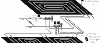
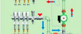
The distributor for underfloor heating visually resembles large heating combs installed in heating points. It also has 2 horizontal collectors - supply and return, to which consumers are connected, in our case - heating circuits. From the ends, coolant is supplied to the collector pipes from the main line - from the boiler room. A typical comb connection diagram is shown in the figure:
To regulate the amount of water flowing into each circuit, valves with a pressure rod are installed on one of the manifolds. Adjustment can be done either manually or using various automation tools, for example, servo drives. To control the amount of coolant, the outlets from the second collector are equipped with flow meter flasks. The comb structure is shown in detail in the diagram:
Here you can see that in addition to the elements listed above, an important part of the comb is the circulation pump. Without it, not a single circuit will be able to work, since it is the pump installed between the two collectors that is responsible for circulating the coolant through the pipes
The very principle of operation of the comb is as follows. The hot water coming from the boiler enters all circuits in the required quantity, stimulated to move by the pump. Moreover, the coolant moves in a circle until its temperature drops below the set one. Since the water temperature is controlled by a three-way valve sensor, after it decreases, the valve will begin to open the way for water from the boiler line, mixing it with the cooled coolant.
When the temperature in the manifold rises to a predetermined limit, the three-way valve will shut off the line again. The comb pump for a warm water floor works non-stop, providing circulation within the system, independent of other heating networks in the house. To empty the unit, the comb design provides for the installation of drain valves. In order to release air from this separate system, the circuit can be supplemented with automatic air vents.
Operating principle and device
When laid out, the ends of the pipes of the heating circuits of the heated floor will converge and connect to the distribution comb in one place. The comb, in turn, is a distribution and mixing unit and performs the following tasks:
To supply the floor system, a liquid temperature not exceeding 45 ° C is needed, but the heat generator, as a rule, heats it at the entrance to the distribution comb to 55 ° C and higher, so the comb serves as a cooling element for the temperature of the liquid that comes from the boiler. You can see prices for manifolds for heated floors in our catalog.
The comb acts as a heat energy regulator, and also performs the function of controlling the flow rate of each circuit and providing the required amount of heat for each individual room.
In appearance, the distributor for heated floors strongly resembles volumetric heating combs, which are installed at heat supply points. It also contains two collectors (return and supply), located horizontally, and also connected to consumers, but in this case - circuits that provide heating. At the end, the boiler room coolant of the main line must be supplied to the collector pipes. Practical wiring diagram for distribution comb as shown in Figure 1:
Figure 1 - Practical diagram for connecting a heated floor collector
The fluid flowing into each circuit is regulated by a valve with a pressure rod, which is installed on one of the manifolds. It is worth noting that it is possible to regulate the amount of liquid using both automatic means (for example, a servo drive) and manually. The adjustment is monitored by specially equipped flow meter flasks, as shown in Figure 2:
Figure 2 — Structure of the floor heating distribution unit
It is noticeable in the figure that, in addition to the parts already listed, one of the most important parts of the distribution comb is the pump that circulates the liquid. Natural movement of liquid in a heated floor is impossible, therefore, in the absence of electricity, operation will not occur. In addition, the operation of the circuit is impossible without a pump, since it is the pump that is responsible for circulating the coolant through the pipes and is installed in the middle of two collectors.
The principle of operation of the comb itself is that the hot liquid circulating through the pump and coming from the boiler enters all circuits in the quantity required. It is noteworthy that the coolant will move in a circular motion until the temperature drops to the set norm or below it, and since the temperature is regulated by a sensor, after it is reduced, the three-way valve begins to allow liquid from the boiler line, while mixing it with the coolant, which has cooled down.
It is worth noting that the three-way valve will close the line even when the temperature rises to a given “ceiling”. In addition, the distribution comb pump (Figure 4) will operate without stopping to provide an internal system that does not depend on third-party heating networks of the building. The distribution comb design also provides for the installation of drain valves to periodically empty the unit.
Collector placement rules
If we are talking about a private house consisting of several floors, collectors are placed on each of them. They will be responsible for the heat supply to the rooms located on the floor on which they are installed. This helps save on fuel. These devices make the circuit of each floor autonomous. If there are rooms on one of the floors that are not used during the day, their temperature can be temporarily lowered.
However, you can adjust the temperature regime not only on the floor as a whole. Sometimes it is enough to turn off just one room or even just one radiator. This procedure will not affect the operation of all other heating devices. In addition, each radiator is heated evenly, since it receives coolant through a separate pipe that fits specifically to it.
If a heating scheme is drawn up for a multi-storey building, each floor should have its own collector, then it will be responsible for the operation of heating devices on that specific floor
Such a heat supply system may seem like a rather expensive structure, but during operation the benefits of its use become obvious. It pays for itself and the costs incurred at the installation stage will no longer seem excessive to you.
If there is a need for urgent repair of any of the circuits or a specific heating device, then the benefits of using a collector become obvious. The repairman will simply disconnect the damaged area or device from the coolant flow by closing the valve at the outlet of the distribution device.
Of course, the use of this heating system has not only advantages, but also disadvantages.
Of course, the pleasure of living in a warm place and being able to save on fuel and possible repair work is not cheap. But over time, all your initial expenses will pay off
For example:
- Significant costs at the installation stage. Plain pipes are cheaper than the high-strength steel needed to make the manifold. This must be taken into account, and then add the cost of the locking mechanisms used in the circuit. As the number of circuits increases, costs also increase in direct proportion.
- Requirement for a circulation pump. Such a pump is simply necessary for the operation of the beam circuit, and this entails increased energy costs.
- Additional expenses. If a separate branch goes to each of the heating devices, you will have to spend money on additional pipes and pay for their installation.
An increase in the volume of work will lead to the fact that it may drag on for a long time. But during operation, this system will be more reliable and efficient.
Comb selection
When buying a structural unit, you need to rely on a number of parameters:
- Material. Brass is highly reliable and affordable. Steel - average cost, but vulnerable to corrosion. Plastic is the cheapest but least durable option.
- Number of taps. Must match or slightly exceed the number of connected circuits.
- Automatic systems. Their number is directly proportional to the cost, the more, the more expensive, but these investments are paid off by reducing the cost of maintaining the functioning of the heating.
Nowadays, products from Danfoss, Kan-Term, Grufell and Fado are very popular.
Rules for installing the comb
The location for placing the collector block must be determined at the design stage of the house. As mentioned above, if this is a multi-storey cottage, then such units should be provided on each floor. It is best to prepare special niches for them, which are located above the floor level.
However, if it was not possible to find a place for the unit in advance, you can install this unit in any room where it will not disturb anyone: in the pantry, in the corridor or in the boiler room. As long as there is no excess moisture in this place.
To keep the unit out of sight, you can place it in a special cabinet, which is offered to their customers by manufacturers of locking mechanisms. The body of this cabinet is made of metal. It is equipped with a door, and its side walls have holes for heating pipes. Sometimes the collector group is simply placed in a niche or on the wall, securing the combs with special clamps.
This comb is placed in a place specially equipped for it. As you can see, it looks quite aesthetically pleasing, and most importantly, access to this node will not be difficult
The pipes that extend from this distribution device are located in the walls or floor and are then connected to the heating radiators. If the pipes are located in the floor screed, the heating appliances should be equipped with an air vent or an air valve.
Installing a comb on a plastic window
You can order the installation of a comb when installing new windows. But if the window frames are already in place, then you will have to do this work yourself. Before you begin the task, you need to figure out what type of mount is provided on a particular crocodile and how to install it correctly. This can be installed under the handle or at the end of the frame. In both cases, the plate with grooves is installed on the fixed part of the profile, and the latch is on the sash.
It is easier for an inexperienced person to attach the fittings under the handle. Any person without special skills and knowledge can perform installation. Installation using any other method will require the help of specialists. Overlap installation requires special skills and knowledge of how to install fittings. If installed incorrectly, the window seal will be compromised.
Consumers prefer fasteners with flush mounting. It has one significant advantage in the form of the ability to be installed in any part of the frame.
The comb is attached to the frame, and the corkscrew is near the handle for locking. The installation process is carried out in stages. First, remove the handle. Then you need to install the lock and screw the handle into place. At the same level where the blocker is installed, a crocodile is attached to the frame profile. After completing all the work, check that nothing interferes with closing the window.
Watching the video will help you make the correct installation. If the comb fails, you will have to reinstall it.
Control elements
Setting up a heated floor collector is impossible without special devices. With their help, the optimal heating mode of the system is established and water flows in the pipelines are regulated. Each of them performs a specific function.
- Water temperature sensor
Installed on the inlet and outlet pipes of the device. These devices do not affect the operation of the system, but indicate the current heating rate. The difference in values can be useful in calculating operating efficiency. They also serve as an indicator of heating mode violations.
- Central thermostat with servo mechanism and sensor.
It is mounted on the inlet pipe of the inlet manifold and connected to the return pipe with cooled coolant. The temperature sensor is placed in the comb body. There is a rotary knob on the body of the thermostat with which you can set the required temperature level. The device receives readings from the sensor about the degree of water heating. Depending on this, the flow of cold and hot coolant is regulated.
- Servo drives on the inlet comb nozzles
According to the principle of operation, they are completely similar to a thermostat, but with minor additions. With their help, the volume of water flow for each circuit of the water floor is regulated. Depending on the model, this can be done in manual or automatic modes. For the latter, servos with built-in temperature sensors are used, which can be connected to a common remote thermostat.
- Flow meters
Devices that are optional for installation, but which, however, can become effective elements for manually controlling the operation of a water heated floor. They are installed on the return manifold pipes and are locking mechanisms with a glass bulb.
When you turn the head on the body, the rod in the device changes its position. This affects the volume of liquid passing through it. For clarity, a measurement scale is printed on the surface of the flowmeter, indicating the flow rate of water l/min.
Scope of application
There is no universal limiter design. Therefore, they choose it based on the scope of application. Euro models are suitable for winter. With their help, the opening of the sash is fixed at a minimum distance. This space is enough to ventilate the room and not cool it more than necessary.
The absolute opposite is the domestic model. It has a large distance between the grooves, which is why it opens to a greater length and provides complete ventilation. Suitable for full ventilation.
Comb selection criteria
The first thing you should pay attention to is what material this structure is made of. The most popular manifolds are made of brass, which are produced by casting
In this case, the result is a strong and durable part, but at the same time it is very expensive.
Welded products made of stainless steel are cheaper. The comb turns out to be quite durable, but this material can be subject to electrochemical corrosion.
Products made from high-quality plastic material are considered a budget option. Their qualities are not inferior to metal parts.
The next criterion for choosing a collector is the number of operational outlets. It is best to choose a product with outlets equal to the number of heated circuits, so that you do not have to plug extra holes.
Next, the technical equipment of the collector is taken into account for automation and regulation of coolant temperature. If you need a comb that will last you a long time, then brass is your option.
If you need a comb that will last you a long time, then brass is your option.
Today, there are combs that can be connected to thermostats and programmable controllers. With their help, it is much easier to make adjustments, as well as control the quantity and quality of coolant in the circuits.
Choosing a comb for heated floors
Separately, it is worth mentioning how to choose the right comb for a heated floor. In this case, you should pay attention to the following criteria:
- the material from which the supply and return manifolds are made;
- the number of circuits on the manifolds in the comb, the permissible level of pressure and water flow;
- degree of automation of the product - what sensors are present in the comb, are there thermostats and other electronics for fine-tuning the temperature in the heated floor circuits;
- manufacturer of combs for heated floors.
Choosing a comb for heated floors
Now we will reveal each of the points in more detail. Let's start with the material from which the comb is made.
Table. Materials used in the production of combs for heated floors.
| Material | Description |
| Brass | Combs for heated floors from this material are made by casting. The result is a fairly strong and durable part, but at the same time expensive. If the price of a comb is not a problem for you, then you should pay attention to brass products. |
| Stainless steel | It is made by welding (followed by careful sealing of the seam). Its strength is similar to brass products, but a stainless steel comb can be subject to electrochemical corrosion. |
| Plastic | Cheap combs made of high-quality plastic that is resistant to high temperatures and pressure. Their quality is almost equal to that of metal products. |
comb for heated floor
Having decided on the material, proceed to consider other parameters of the comb. And the most important of them is the number of taps on the collectors. Ideally, it should be equal to the number of circuits in the floor heating system. But combs with a large number of outlets are also allowed - in this case, plugs must be used. Even before purchasing, it is advisable to make simple calculations and determine what pressure and fluid flow will be in your system. The comb must be suitable for the conditions in which it will work. In this case, it is desirable to have a certain “margin of safety” in case of a sharp increase in pressure or coolant flow in the system.
Assembly of the collector unit in the case of a combined system: radiators + heated floor
Next, you need to decide what degree of automation and temperature and flow control you need. Today on the plumbing market there are technically advanced combs that can be connected to thermostats and programmable controllers. With their help, you can constantly adjust the temperature and flow on the circuits in accordance with the weather outside and the needs of the residents. At the same time, the high price of the product is compensated by additional savings on coolant.
A set of combs for heated floors with automatic regulation using a set of temperature sensors placed directly in those rooms that are heated
And finally, always pay attention to the country and manufacturer. As a rule, combs for heated floors made by European companies are of better quality, but also more expensive. An alternative to them may be domestic and Chinese devices, which are inferior in their durability and reliability, but at the same time are much more affordable for the common buyer.
Important! When purchasing an expensive comb for heated floors, make sure that it is not a counterfeit masquerading as a well-known company with a good reputation. To do this, it is advisable to familiarize yourself with the various certificates that the seller of this product must have.
The comb or collector of the heated floor is located in a special cabinet (mounting box)
How to build a collector yourself
You can buy a ready-made connection, choosing one that would approximately meet the needs of your home. But achieving an exact match is quite difficult. Therefore, it is better to make a heating comb yourself. Let's figure out what is needed for this.
Planning stage
There are a number of parameters of the heating system of the house that you should know when building a unit.
- The number of circuits through which heated water will pass.
- The number and technical characteristics of the heating equipment included in the scheme.
- Additional equipment involved in installation. This refers to pressure gauges, thermometers, taps, storage tanks, valves, pumps, etc.
It is also necessary to provide for the possibility of increasing the load if over time it is necessary to build in elements that were not taken into account in advance. This could be, for example, solar panels or a heat pump.
It is necessary to foresee in advance not only the number of circuits operating in the heating system, but also additional equipment that will be included in the overall scheme
Determining the block design
The design of the future node depends on the connection point of each circuit. After all, there are some connection nuances that cannot be ignored.
- Boilers (electric and gas) must be connected to the comb from above or below.
- The circulation pump should be connected from the end of the structure.
- Solid fuel units and indirect heating boilers also need to be cut in from the end.
- The supply circuits of the heating system are connected from below or from above.
For clarity, it is necessary to make a drawing of the future compact and neat unit. This will help determine the quantity and types of materials we will need. All necessary dimensions and threaded connections with thread pitch are also applied to the drawing. All circuits should be marked to guide the drawing when connecting.
This drawing shows a four-way manifold. You may not make a drawing and will limit yourself to a sketch, but do not forget to put on it all the dimensions necessary for the work
The distance between the nozzles of both combs should be from 10 to 20 cm. These are the optimal parameters for maintenance. The distance between the supply and return combs themselves should be within the same limits.
Sequence of work
To make both combs, not only round, but also square pipes can be used. The sequence of work performed is as follows:
- In full accordance with the parameters indicated on the drawing, we purchase all the necessary materials.
- According to the drawing, we make the connection by welding pipes, taking into account their subsequent functions. Welding areas should be cleaned with a wire brush and degreased.
- Testing a homemade unit is a necessary stage of work. To do this, all pipes are hermetically sealed except one, through which hot water is poured into the system. Let's take a good look at all the joints: they shouldn't leak.
- Now the collector can be painted and dried thoroughly.
- Next, you should connect pipes, locking mechanisms and control equipment to it.
After this, the device is ready for use
This will differ favorably from purchased products in that it is built taking into account the needs of a particular home, and this is very important for its further operation. Of course, a high-quality and functional device can only be obtained if the master knows how to handle a welding machine and metalworking tools
In order for a homemade collector block to work more efficiently than a purchased one, the master needs to be able to handle both welding equipment and plumbing tools
You can learn how to make a polypropylene manifold by watching this video:
Heating rooms using water heated floors is considered one of the most effective ways in terms of energy savings and uniform heat distribution. As you know, heating is carried out through pipes with coolant laid in a screed. Each room is a separate closed circuit, or even several. Their operation is controlled by one common unit - a comb for heated floors. Information about how this unit functions, the nuances of its assembly and regulation is brought to your attention in this article.
DIY comb for heated floors
An alternative to a factory-made heated floor comb can be a product that you assemble yourself. As a rule, in this case, shut-off valves, various sensors and other complex elements of the system are purchased separately, and the supply and return manifolds are made by hand from polypropylene pipes. Let's look at a little step-by-step instructions for this process.
Step 1. Prepare materials and tools. First of all, you will need polypropylene pipes designed to work at high temperatures, and the same tees. In addition, take fittings for connecting shut-off valves, thermal heads and pipes of the heated floor system. As for the tools, you will need a tape measure, scissors for polypropylene pipes and a soldering iron for them with a set of nozzles of different sizes.
Preparing everything you need
Important! Remember that a soldering iron for polypropylene pipes heats up to high temperatures. Therefore, to avoid getting burned during work due to negligence, use protective gloves.
Step 2. Heat the soldering iron to the desired temperature, prepare a pipe and tee from polypropylene. Clean and degrease their edges to ensure high-quality soldering of the elements.
Preparing the pipe and tee
Step 3. Place a fitting on one side of the soldering iron caliber (its inner surface should be heated) and a polypropylene pipe (here it’s the other way around - you need to heat up the outer one). Keep them like this for some time.
The connected elements are kept for some time
Step 4. After this, take and connect the polypropylene pipe and tee together. At the same time, try not to rotate them relative to each other.
The pipe is connected to a tee
Step 5. Trim the pipe to leave only a small section of it necessary to secure the next tee as part of a homemade polypropylene manifold.
Pipe cutting
Step 6. Using the same principle, connect the following fittings with polypropylene pipes.
Connecting other fittings to pipes
Step 7. Complete the creation of a comb for a warm floor with your own hands by securing couplings for connecting pipes from the circuits, shut-off valves and an air release valve. The image below shows the finished product, designed to distribute the coolant into two sections of the heated floor.
All is ready
Working with Manifold Flow Meters
Hydraulic balancing of underfloor heating loops involves normalizing the flow in each coil. Depending on the length, different amounts of incoming coolant may be required so that when passing through the loop it cools exactly to the calculated value. The required flow is quantitatively determined as the ratio of the thermal load on the loop to the product of the heat capacity of water or other coolant and the temperature difference in the supply and return: G = Q / s * (t1 - t2).
You can often find recommendations to determine the coolant flow according to the performance of the circulation pump, that is, to divide its supply in proportion to the ratio of the lengths of the loops. Such advice should be avoided: in addition to the fact that it is quite difficult to calculate the length of each coil, one of the most important rules is violated - choosing equipment parameters based on the needs of the system, and not vice versa. Attempts to distribute flow in the described manner almost always lead to the fact that the flow in the loops differs significantly from the calculated values, which makes further adjustment of the system impossible.
Adjusting the flow with flow meters is quite simple. In some models, the throughput is changed by turning the body, in others - by rotating the rod with a special key. The scale on the flow meter body indicates the flow rate in liters per minute; you just need to set the float to the appropriate position.
Almost always, when the capacity of one flow meter changes, the flow rate in the remaining loops changes, so the adjustment is carried out several times, sequentially calibrating each outlet. If such changes are particularly pronounced, this indicates a lack of capacity of the control valves through which the collector is connected, or that the performance of the circulation pump is too low.
Installation of the comb in the heating system and its calculation
Comb in a water heated floor system
The installation location of the distribution comb in the heating system depends on its purpose. Most often it is used to organize multi-circuit heat supply. However, in addition to this, it is a mandatory element of a water heated floor.
Before proceeding with installation, you should calculate the heating comb. The main task of this process is the uniform distribution of pressure along the heating circuits. If the system is a complex circuit of highways, it is recommended to make calculations using special programs. For a simple system with up to 5 circuits, you can apply the principle of equal sections.
N0=N1+N2+N3+N4
Where N0 is the diameter of the collector, N1, N2, N3, N4 are the sections of its outlet pipes.
The same calculation scheme is used when making a heating comb with your own hands
It is important that the dimensions of the inlet and outlet manifolds match. It is noteworthy that the standard heating comb device has no requirements for its shape
Those. it can be either round or square. The basic principles for installing collector heating are as follows:
- To improve circulation, it is recommended to install pumps for each circuit. In this case, the distribution comb of the heating system should not ensure synchronization of the pumps;
- If the unit is located in a boiler room, installation of a protective box is not necessary. An exception is the installation of a heating comb made of polypropylene in a heated floor system;
- To adjust the coolant volume, it is necessary to install control fittings on each inlet and outlet pipes - inlet valves and balancing flowmeters;
- When planning the installation of a heating comb, it is necessary to provide for the presence of a safety group at the distribution unit.
Example of a heating comb installation diagram
It should be remembered that these are only general recommendations that can be changed and supplemented depending on the specific parameters of the heating system.
In addition to these rules, experts advise when calculating the heating comb to take into account the difference in the length of the circuits. It is recommended to draw up a diagram so that their length is approximately equal.
To reduce energy consumption, a mixing unit can be installed in the heating comb device, which, in turn, will reduce heating costs.
The comb for heated floors is considered easy to use.
To turn off the water supply to the room, just turn the tap. The comb allows you to save on electricity by heating only those rooms and areas of the house that are used during a certain period of time. The temperature is also easy to adjust. Water supply and return taps are located at different levels. And the pump is located on the side and operates from the network. The speed of water supply into the system depends on its power.
Installation and connection of all parts of the comb is carried out in a specially designated place. Typically this is the area of the wall that is closest to the boiler. A hole of the required depth is knocked out in it, and a collector cabinet is installed. The dimensions of the cabinet depend on the number of pipe circuits and pump volumes.
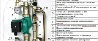
The design of the comb must include:
- thermostat,
- pressure gauge,
- flow meter,
- 2 transit pipes,
- ball valve,
- galvanized bracket,
- additional components.
The main advantage of a comb for a heated floor is its ability to evenly distribute thermal energy across the available coolants. This allows you to distribute heat throughout the room as evenly as possible and eliminate temperature changes.
In addition, thanks to the manifold, a strong and durable connection in the system is achieved. The collector is hard to damage, and if repairs to part of the system are still necessary, it can be done by turning off the water supply to the problem circuit. In this case, other circuits will operate as usual.
Product installation features
When installing this structure, it is necessary to take into account a number of rules and features. Typically the collector is installed on the wall, in the middle or closer to the floor. To do this, it is best to use a special manifold cabinet, which gives a more aesthetic appearance to the structural unit.
It must have holes drilled for suitable piping. The comb is attached in such a way that it is possible to bleed air from the heating circuits. This will allow you to carry out repairs without problems in the event of an accident.
The length of the contours should be approximately the same to make adjustments easier. This is done based on two indicators: coolant flow and temperature. For this purpose, a flow meter and temperature sensors are built into the circuit.
An important condition when installing heated floors is that the total length of each circuit should not exceed 60 m. Otherwise, it will be difficult for the coolant to overcome the hydraulic resistance in the pipelines
When creating a warm floor, each room has its own separate heating branch.
This is due to the fact that there are restrictions on the length of one branch, as well as ease of installation.
The distribution of coolant from a single boiler flow to each branch occurs in a special unit called a manifold, or comb for heated floors.
With your own hands, you can make an analogue to a factory manifold, which will perform its functions no worse, but for less money. What you need to buy, how to assemble and install it correctly in practice.
How to set up a heated floor comb with flow meters
A flow meter is a device that facilitates the correct functioning of floor heating equipment. The device is most often used for balancing multi-circuit systems with liquid coolant. It is installed directly in the collector. Only proper installation and adjustment of heated floor flow meters can ensure high-quality heating of the building.
The main function of flow meters or, as they are also called, float rotameters in a heated floor system is to regulate the coolant flow in water circuits. Installing such a device allows you to:
- avoid excessive consumption of electrical energy in the process of heating the coolant;
- ensure uniform heating of all water circuits;
- eliminate temperature fluctuations in different rooms.
The need to use flow meters arises in buildings where floor coverings of different areas are heated. Large rooms require a longer pipeline length, so they heat up less intensely than small rooms. Therefore, it is possible to achieve uniform heating and ensure a comfortable temperature throughout the entire house only with such a device.
The flow meter for a floor heating system is a mechanical type device with a plastic or brass housing. Inside it is a float made of polypropylene. On the top of the body there is a transparent bulb with markings. During the circulation of the coolant, the float comes into action, moving up and down. According to its location, you can use a scale to determine the volume of liquid in the pipeline.
The quality of functioning of the underfloor heating system depends on the correct selection of the flow meter. Three types of rotameters are produced:
- Measuring. This type of flow meter is installed with a manual adjustment valve. Control is carried out taking into account measurement readings.
- Regulating. It performs only one function - controlling the amount of coolant entering the water circuits.
- Combined. Such a device combines two actions - adjustment and measurement. The cost of the product is significantly higher than that of models performing the same type of functions.
When purchasing a flow meter for heated floors, you should pay attention to the following product parameters:
- Case material. Devices made of brass have high wear resistance. The top of such a body should be covered with nickel. Plastic products are cheaper, but they have a reduced strength rating.
- Device integrity. Before purchasing a rotameter, it is recommended to carefully inspect the housing and transparent bulb to exclude the presence of cracks or other defects.
- Inner part. The spring in the middle of the flowmeter body should be made of stainless steel.
- Flask. The transparent cap with a measuring scale in high-quality models is made of polycarbonate. This material is quite strong and has high heat resistance, which is especially important when used in heating systems.
- Specifications. The instructions supplied with the device indicate the temperature level. This indicator should be no lower than 110 degrees. Also equally important is the pressure - at least 10 bar.
- Maximum throughput value. The rotameter must be able to conduct at least 2-4 meters of coolant through itself in an hour.
Flow meter for heated floors
The manufacturer of the product should also be considered. The main indicator of the reliability of a product is the availability of a quality certificate and the provision of a guarantee, which responsible companies offer for up to five years.
According to the manufacturers' instructions, the rotameter is connected to the return collector, but there is an option to install the device on the supply.
The main requirement for installing the device is its vertical location. This installation allows you to determine the exact value of the liquid level in the flask. Therefore, the comb must be placed strictly horizontally in level.
The rotameter is connected by screwing into the corresponding socket on the manifold. The device comes with an O-ring and a union nut. There is no need to additionally seal the device with sealant or other materials.
The workflow of the connected circuit manifold - manifold and flow meter must be fully automated. Therefore, a temperature sensor is additionally connected to the system. With this scheme, when the specified temperature regime of the coolant is reached, the system blocks its full or partial access to the circuits.
Installation of heated floor flow meters
The entire installation process and adjustment of the rotameter for heated floors is performed in the following sequence:
- The flow meter must be screwed into a specially designed technological hole on the manifold. The device is installed using a key in a strictly vertical position.
- Turn counterclockwise and remove the transparent bulb located at the top of the flowmeter housing. After this, you need to remove the ring that is installed for protection by the manufacturer. Then put the cap with the markings back on.
- Turn the body clockwise to the required pressure level. This action is a balancing of the coolant flow rate. In this case, the specified value should be displayed on the scale.
After such actions, it is necessary to check the operating process of the entire underfloor heating system. During operation of the heated floor, do not close the flask on the flow meter. The scale must be constantly visible, since sometimes there is a need for balancing during operation of heating equipment.
According to technical rules, identical installation of several contours, including their length, should be carried out. Otherwise, even using a collector with a rotameter will not give a positive result, and the system will not function correctly.
For each individual room, the rotameters are adjusted separately. Control is carried out according to the diagram of the installed circuits. In this case, the level of heating of the liquid and pressure is taken into account.
It is recommended to carry out balancing according to the following instructions:
- The total amount of coolant passing through the collector in one minute is determined. Indicators are taken in liters. The resulting value is taken as 100 percent.
- The percentage flow rate of each individual water circuit is calculated. The result is converted to liters per minute.
- The flow meter regulates the amount of liquid supplied to the pipeline.
Using these steps, you can perform long-term adjustments to the water circuit. To indicate the actual parameters, it is necessary to observe the flow meter readings. According to observations, it is possible to accurately determine the flow rate of the circuits connected to the collector.
Manifold with flow meters for heated floors
The flow meter is adjusted depending on the installed model. After connecting the device to the manifold, preliminary settings should be made by setting the initial position, which allows access to liquid.
In rotameters without a built-in valve, an additional locking device is used to set the “open” position. In this case, balancing is performed during the operation of the system.
Combination devices for metering coolant flow can be pre-set using full turns of the built-in valve. Each turn allows you to reduce the clearance by a set value.
Adjustment of the flow meter of the floor heating system is carried out taking into account the control of the fluid speed in one minute - from 0.5 to 5 liters.
Before setting up the rotameter, you should check the condition of the installed circuit. Trial testing is necessary to exclude the presence of leaks in the circuit, which could cause distortion of the indicators in the device.
The flow meter is an important element in a multi-circuit underfloor heating system. The device allows for a uniform flow of liquid into all individual pipelines. In order for heating equipment to function as efficiently as possible, you must select the right rotameter, as well as install and configure it in accordance with technical requirements.
When creating underfloor heating systems, special distribution elements are used - manifolds for heated floors .
The design of such products is represented by two so-called combs - pipes that have several outlets on one side.
One serves to supply coolant to the system, the other to remove cooled liquid. Together, they perform the function of monitoring the temperature of the entire system and the uniform distribution of heat throughout all heating circuits.
The operating principle of a heated floor comb is quite simple. First, hot liquid flows from the general heating system into the manifold supply valve.
There it is mixed with cooled water that has passed through the heated floor circuit until a certain temperature is obtained.
Further distribution along the circuits is regulated by the position of a special distribution valve on the multi-port valve of the comb, depending on the current heating of the coolant. The cooled liquid accumulates in the return manifold under pressure, from where it then passes into the supply pipe to repeat the cycle.
How to properly assemble a comb for a heated floor and what it consists of, find out from the diagram below.
Installation of the comb is carried out according to certain conditions:
- The comb is mounted on the wall at an average height or closer to the floor. You can also use a special manifold cabinet, which provides convenience and an aesthetically pleasing design. This shell can be installed either in a recess, according to pre-calculated parameters, or in the usual way on the floor or wall. However, the installation level must comply with the following point. After installing the manifold cabinet, two holes are made in it (one for the supply pipe, the second for the return pipe), after which the structure itself is installed
- The distributor must be located above the level of the heating main so that, in the event of an accident, excess air can be removed from the underfloor heating system.
- The maximum length of each of the coolant circuits connected to the collector should be approximately the same.
- After installing the distributor, all functionality is attached to it (pump, taps, valves, air vents).
- Configure and adjust the resulting system of underfloor heating circuits.
system can be adjusted manually using the following parameters:
- Coolant consumption.
- His temperature.
The first value is set according to your own calculations or known data by changing the speed mode of the circulating pump. You can monitor the liquid flow rate using an installed flow meter.
The second value is set by turning the thermostat wheel (built-in or remote). Auto-adjustment consists of installing servos on each tap. They will be able to set the required values for each circuit by remotely interacting with thermostats.
A flow meter is a small device installed at the outlets of the return manifold. It serves to shut off the flow of coolant into the system when a certain temperature is reached.
The absence of a flow meter will not lead to system failure. But in this case, the heat supply will be uneven and energy-consuming.
Using a pump, water circulates between the parts of the collector. Coolant circulation is the basis for the operation of the structure. The device consists of the following elements:
- Automated supply valve - necessary to change the mode of water supply from the heating pipe.
- Thermal sensor - records the temperature of the coolant.
- Circulation pump - directs fluid through the circuits.
- Control elements - installed on the inlet and outlet pipes of the comb. Necessary for system automation.
In general, the process of installing a comb for an underfloor heating system with your own hands is not that complicated. Following certain instructions and rules, installation will not be difficult, even for the average person.
To see how to connect a comb for a heated floor with your own hands, watch the video:
For review, assembly, installation and adjustment of the comb for heated floors, watch the video:
We learn how to select a pump and a three-way pump for a heated floor in the video below:
Two way valve design
In the heated floor installation scheme, the valve is installed directly in front of the comb. It is connected to a temperature sensor, which is placed at the coolant return manifold. In addition, the distribution node diagram includes:
- circulation pump;
- balancing valve;
- check valve
The check valve is part of the comb.
At the beginning of the heating process, the device is open and the coolant enters the collector. The valve remains open until the water temperature reaches the operating value. As soon as this happens, the “sensor + thermal head” tandem will close it, and the coolant will stop flowing from the heating boiler.
During this period, the floor heating comb pump will independently circulate hot water through the heating circuits. In this case, the coolant will gradually cool down, and when its temperature drops below the operating temperature, the valve will open again.
Proper mixing of hot and chilled water occurs due to a balancing valve that regulates the volume of waste coolant.
Role in heating system and design
Different circuits connected to the same system have different lengths, and therefore different volumes. A comb for a warm floor is installed to regulate the amount of coolant entering each circuit. Additionally, it maintains a certain level of water temperature to avoid excessive overheating or cooling. A system of temperature sensors that connect to the valves is responsible for this.
If there is a lack of heat, the damper on the pipe coming from the boiler opens, and hot water enters the mixing unit, which is combined with cooled water that has already been passed through the heating circuit. If the temperature corresponds to the specified value, the valve remains closed.
In addition to the elements mentioned, the comb device for heated floors includes:
- A hot water supply manifold connected by flow meters, which distributes the coolant among the circuits.
- Chilled water outlet manifold with thermostatic valves that regulate heating power. The cooled coolant enters here.
- Shut-off valves that completely shut off water circulation.
- The circulation pump ensures the movement of water in the circuits.
- The drain valve is responsible for draining liquid from the system, and the air valve is responsible for removing excess gas.
A heated floor comb with a pump is equipped with a valve that regulates the volume of hot water added to the system in order to maintain a certain temperature. Two types of parts are used: with two or three passages. The first is highly reliable, but has a limited heated area of 150 m2. The second is capable of providing much larger rooms, but is less resistant to damage.
How does the collector work?
Water floors are laid in various ways, for example, concrete or flooring, but regardless of the technology chosen, it is necessary to purchase and install a manifold cabinet.
Note: It is recommended to install the collector box on the wall as close to the middle as possible and most often near the floor.
In the future, two pipes will be inserted into it:
- supply, which leaves the boiler and supplies hot coolant to the system;
- return, which performs an absolutely opposite role: it serves to collect water that has already been used and has had time to cool. It is returned back to the boiler, and the process is repeated again.
The cyclical nature of the process is ensured by another built-in component of the system - a circulation pump. One way or another, during the operation of a heated floor, say during repair work, the system has to be turned off. To do this, each of the pipes is equipped with shut-off valves. A plastic pipe and a metal shut-off valve are connected to each other through a compression fitting. Then a comb is connected to the valve, mounting an air vent on one end and a drain valve on the other. After assembling the cabinet, they proceed directly to installation. And only with a comb already installed on the wall can you cut the circuit pipes to length.
Note: To ensure the tightness of the connection, the pipes are cut strictly at a right angle.
How to build a collector yourself
You can buy a ready-made connection, choosing one that would approximately meet the needs of your home. But achieving an exact match is quite difficult. Therefore, it is better to make a heating comb yourself. Let's figure out what is needed for this.
Planning stage
There are a number of parameters of the heating system of the house that you should know when building a unit.
- The number of circuits through which heated water will pass.
- The number and technical characteristics of the heating equipment included in the scheme.
- Additional equipment involved in installation. This refers to pressure gauges, thermometers, taps, storage tanks, valves, pumps, etc.
It is also necessary to provide for the possibility of increasing the load if over time it is necessary to build in elements that were not taken into account in advance. This could be, for example, solar panels or a heat pump.
It is necessary to foresee in advance not only the number of circuits operating in the heating system, but also additional equipment that will be included in the overall scheme
Determining the block design
The design of the future node depends on the connection point of each circuit. After all, there are some connection nuances that cannot be ignored.
- Boilers (electric and gas) must be connected to the comb from above or below.
- The circulation pump should be connected from the end of the structure.
- Solid fuel units and indirect heating boilers also need to be cut in from the end.
- The supply circuits of the heating system are connected from below or from above.
For clarity, it is necessary to make a drawing of the future compact and neat unit. This will help determine the quantity and types of materials we will need. All necessary dimensions and threaded connections with thread pitch are also applied to the drawing. All circuits should be marked to guide the drawing when connecting.
This drawing shows a four-way manifold. You may not make a drawing and will limit yourself to a sketch, but do not forget to put on it all the dimensions necessary for the work
The distance between the nozzles of both combs should be from 10 to 20 cm. These are the optimal parameters for maintenance. The distance between the supply and return combs themselves should be within the same limits.