Typical connection diagrams
Water heated floors are rarely used as the only source of heating. Heating only due to underfloor heating is permissible only in regions with a mild climate, or in rooms with a large area, where heat removal is not limited by furniture, interior items or the low thermal conductivity of the floor covering. Almost always it is necessary to combine radiator circuits, hot water preparation devices and underfloor heating loops in one heating system.
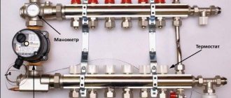
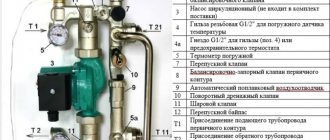
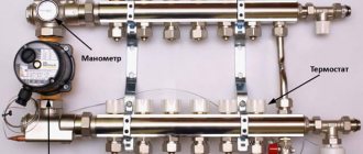
Typical diagram of a combined heating system with connection of radiators and underfloor heating circuits. This is the most technologically advanced and easily customizable option, but it also requires significant initial investment. 1 - heating boiler; 2 — safety group, circulation pump, expansion tank; 3 - manifold for separate two-pipe connection of radiators in a star configuration; 4 — heating radiators; 5 - underfloor heating manifold, includes: bypass, three-way valve, thermostatic head, circulation pump, combs for connecting underfloor heating circuits with gearboxes and flow meters; 6 - heated floor contours
There are quite a large number of variations in the design of the boiler room piping, and each individual case has its own principles of operation of the hydraulic system. However, if you do not take into account very specific options, then there are only five ways to coordinate the operation of heating devices of various types:
- Parallel connection of the underfloor heating collector to the main line of the heating unit. The insertion point into the main line must be made up to the connection point of the radiator network; the coolant supply is provided by an additional circulation pump.
- Association according to the type of primary and secondary rings. The line, wrapped in a ring, has several supply connections in the supply part; the coolant flow in the connected circuits decreases with distance from the heating source. Flow balancing is performed by selecting the pump supply and limiting the flow with regulators.
- Connection to the extreme point of a coplanar manifold. The movement of the coolant in the heated floor loops is ensured by a common pump located in the generator part, while the system is balanced according to the principle of priority flow.
- Connection through a hydraulic separator is optimal when there are a large number of heating devices, a significant difference in flow rates in the circuits and a significant length of underfloor heating loops. This option also uses a coplanar manifold, but the hydraulic arrow is necessary to eliminate the pressure drop that interferes with the correct operation of the circulation pumps.
- Local parallel loop connection via unibox. This option is well suited for connecting a short-length heated floor loop, for example, if you need to heat the floor only in the bathroom.
The simplest option is to connect a heated floor circuit to a radiator heating system with a coolant temperature of 70-80 °C. 1 - line with supply and return of the high-temperature circuit; 2 - heated floor contour; 3 - unibox.
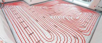
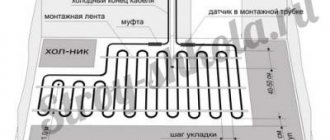
It must be remembered that the nature of the operation of a heated floor may also change depending on the installation pattern of the coil. The “snail” scheme is considered optimal, in which the tubes are laid in pairs, which means that the entire area is heated almost evenly. If the warm floor is arranged as a “snake” or “labyrinth”, then the formation of colder and warmer zones is practically guaranteed. This drawback can be eliminated, including through proper configuration.
Features of setting up a Valtec manifold without flow meters
If the manifold is not equipped with flow meters, but only with valves, you will have to set the flow rate by touch. This is not figurative, but literally. Knowing the length of each circuit, we open the flow to the maximum on the longest one. We screw the rest approximately. You can count the number of valve revolutions and focus on them.
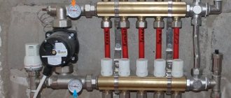
Manifold for underfloor heating without flow meters
Next, we turn on the heating and wait until the floor warms up. If you have a thermometer, measure the floor temperature in the operating area of each circuit. There is no thermometer - we feel and compare sensations. Based on the results, we adjust the position of the valves and wait again for several hours. We continue this way until we are satisfied with the result. In principle, a Valtec manifold with valves without a flow meter is not that difficult to configure.
Evaluating collector settings based on return temperature
This check is based on the fact that with a correctly adjusted flow rate, the return temperature on all circuits should be the same. To set up or check this type, you need special thermometers. They are installed on the return pipeline between the manifold inlet and the pipe.
You can adjust the collector using a return thermometer
The temperature of the longest circuit is taken as a reference - all the others are adjusted to it. Only the adjustment results will need to be corrected after a few hours. When the floor heated by adjustable circuits warms up or cools down (depending on the adjustment) and the temperature in the return pipe changes again. It will take several such adjustments until the difference becomes insignificant.
KERMI manifold with flow meters for 7 branches of underfloor heating, winter is coming, help me set it up, explain the principles.
in a larger boiler there is more water, in a smaller one, less. Turn the handle and the float goes up and down.
=) The principle is clear, as I understand it, the flow meter sets the overall adjustment scale, and then the thermal valve sets the adjustment within this scale?
Setting up a warm floor
And now, the heating system is filled and tested, the boiler is started. Everything is ready to set up the heating system.
Before you start setting up heating, you need to decide on its goals and objectives. The main task of balancing is not to establish the required flow rate in each loop, but to establish the ratio of flow rates across loops or flow balance. It is worth remembering that the final flow rate is set during setup of the pumping and mixing unit. By changing the total coolant flow through the collector, the ratio of flow through the loops will remain the same.
Setting up heated floors using flow meters
The presence of flow meters on the collector block has a significant effect on balancing. Flow meters significantly speed up balancing and allow it to be done without turning on the boiler. This is possible because the flow meter shows the coolant flow for each circuit in real time.
The distribution of coolant flows must be carried out in such a way that the ratio of flow rates along the loops and the ratio of the required thermal powers coincide. To achieve this, it is advisable to know the required thermal loads on the hinges. But even if this data is not available, you can set the costs in proportion to the lengths of the loops. In most cases, this approach does not produce a large error due to the fact that loops with large lengths also have greater powers.
Balancing starts with the longest loop or the highest power loop if known. Next, the control valve on this loop opens to its maximum position. In the future, the costs of all other loops will be billed in relation to it.
For example, consider a manifold with four loops. Let us assume that the loop lengths are as follows: 100, 75, 75 and 50 m.
As we have already said, the setup starts with a larger loop, which is 100 m long. It opens to the maximum. Let us assume that with the valve fully open, the flow rate in this loop is set at 4 l/min.
The coolant flow rate on the second and third loops should be: (75/100) · 4 = 3 l/min.
The coolant flow on the fourth loop should be: (50/100) · 4 = 2 l/min.
Problems when setting up a heated floor
In practice, it may turn out that on the third loop the flow rate with the valve fully open will be set at 2.5 l/min, although we need a flow rate of 3 l/min. This suggests that this loop has greater hydraulic resistance than a second loop of the same length. As a rule, this happens due to the presence of a larger number of branches, rolls or supply areas. If this happens, then you will have to turn on the boiler and carry out further balancing with the boiler on and at least with minimal heat removal in the room.
In this case, the first loop will be adjusted to (100/75) 2.5 = 3.3 l/min, the second loop to 2.5 l/min, and the fourth loop to – (50/75) 2.5 = 1.6 l/min.
After all the costs in the loops have been set, the balancing of the underfloor heating loops can be considered complete. The next step is setting up the pumping and mixing unit.
Setting up a heated floor without flow meters
If flow meters are not installed on the collector, then the flow rates in the loops will have to be judged only by indirect evidence.
Balancing without flow meters is carried out only with the boiler on and at least with minimal heat removal in the room. It is better if the temperature outside is not lower than +5 ºС, while there should be no open windows or any significant heat emissions in the rooms, for example, a working fireplace. After this, the system must be left to warm up for several hours until the temperature in the loops has stabilized, after which it is necessary to evaluate the correctness of the settings.
The correct system setup is determined in one of the following ways:
- by the temperature of the coolant in the return pipeline;
- based on average floor temperature.
Manual adjustment of coolant temperature
How you adjust the temperature will depend entirely on the equipment you are using. For example, if a system with a temperature controller and a servo drive is installed, then the setup is carried out according to the instructions from the manufacturer of this device. In this case, the adjustment is performed automatically. Now let's look at the manual method of setting the temperature using thermal heads.
Thermal heads can be installed both on the supply and return side of the coolant.
First of all, the system up to the heated floor must be completely filled with coolant and freed from air.
But it is important not to rush here, otherwise air jams may form. If the connection was made from the boiler, then before starting water into the heating circuits, turn off all taps
Afterwards, open the supply/return loop on one loop, filling it with coolant. The air should come out of it through the air vent. Now turn on the circulation pump so that the coolant begins to move in this loop. At the same time, turn the temperature on the boiler to 35°. To the touch you should feel that hot water is flowing in the return and supply in the heating circuit. If everything works properly, close this loop and open a new one. Using this method, you pump and check each loop of the heating circuit. When you have configured each circuit, you open all the taps and adjust the required temperature by touch. In some loops the faucet will need to be opened completely, while in others it is enough to open it slightly.
The coolant temperature in each circuit may be different. There are several reasons for this, such as the length of the loop. The shorter the circuit, the faster it warms up and vice versa.
Thus, manual temperature adjustment is carried out. It is enough to do it once a year. But here it is important to take into account the nuance. The underfloor heating system is inertial. What does this mean in practice? If you make changes to one of the hinges, you will have to wait several hours to notice a noticeable change in the temperature inside the room.
If you installed flow meters on the collector, the difference between the readings can reach up to 0.5 liters.
Functionality and principle of operation of the flow meter
The main function of flow meters or, as they are also called, float rotameters in a heated floor system is to regulate the coolant flow in water circuits. Installing such a device allows you to:
- avoid excessive consumption of electrical energy in the process of heating the coolant;
- ensure uniform heating of all water circuits;
- eliminate temperature fluctuations in different rooms.
The need to use flow meters arises in buildings where floor coverings of different areas are heated. Large rooms require a longer pipeline length, so they heat up less intensely than small rooms. Therefore, it is possible to achieve uniform heating and ensure a comfortable temperature throughout the entire house only with such a device.
The flow meter for a floor heating system is a mechanical type device with a plastic or brass housing. Inside it is a float made of polypropylene. On the top of the body there is a transparent bulb with markings. During the circulation of the coolant, the float comes into action, moving up and down. According to its location, you can use a scale to determine the volume of liquid in the pipeline.
How to choose a quality flow meter
The passport indicates the main characteristics of the flow meter, so when choosing a device you need to pay attention to the following characteristics:
- Float rotameters are the cheapest; among them you need to choose devices with a brass body.
- Inner spring material. If it is not indicated, it means that the manufacturer installed an unreliable plastic container.
- The passport must indicate that the spring is made of stainless steel.
- Flask material. As a rule, in all float rotameters the flask is made of polycarbonate. But there are also exceptions. The flask should have a clear and understandable scale.
- Maximum pressure. The flowmeter must withstand 10 bar.
- Maximum temperature. For underfloor heating systems, the upper operating temperature limit should be at least 90 degrees. It is better if it is above 100.
- Bandwidth. You need to select a device in accordance with the power of the circuit. The bulk of flow meters are designed for flows from 2 to 4 cubic meters per hour.
- Quality equipment is always guaranteed for at least 5 years.
How to adjust a warm water floor manually preparation and input
Manual adjustment is carried out using a conventional tap called a thermal head. It is mounted on the return and supply. Using a crane allows you to avoid loading the system with automation and additional equipment. This significantly reduces costs, but creates a number of inconveniences. High-quality and quick adjustment of a warm water floor with a thermal head is a myth. You will have to turn the tap often, and when determining the temperature, rely solely on personal sensations.
Important! It is considered more convenient to regulate water heated floors using rotameters (flow meters), which are installed at the entrance to each circuit (manifold installation location). All you need is to control the permissible difference in instrument readings
It is 0.3-0.5 l.
Correct adjustment of a heated floor with a thermal head requires compliance with the commissioning standards of the entire system. Otherwise, the system of main or auxiliary heating of air masses from below the room will malfunction.
Results
It is important to ensure that when the water floor heating system is operating, the flow rate on the collector is visible. This is necessary for maintenance. Each water circuit must have its own flow meter.
We recommend: How to repair underfloor heating?
As you can see, in the equipment, each element performs its own functions, so each one needs to be given sufficient attention, and in order for the entire system to work as one whole, it is worth equipping it with a flow meter and a collector, which will evenly distribute all the heat.
- Related Posts
- How to install a film heated floor?
- How to lay heated flooring under laminate on a wooden floor?
- How are PEX pipes connected for heated floors?
- What should a laminate be like for a warm water floor?
- How much does a heated floor consume?
- Which is better, warm floors or radiators?
Temperature
Before you begin adjusting the heated floor, it is extremely important to establish a clear understanding of the purpose for which it is being done. According to the principle of operation, water-heated floors are fundamentally different from other heating devices.
The main difference is the operating temperature of the coolant. If the radiator network is supplied at temperatures up to 80 °C, then the heating of the coolant entering the heated floor coil is limited to 40–42 °C. This need is due to reasons of comfort and safety. In normal mode, the temperature on the floor surface fluctuates in the range of 22–26 °C; stronger heating causes unpleasant sensations.
There are two ways to regulate the heating temperature of a liquid heated floor. The first of them involves controlling the temperature on the supply branch of the collector by mixing in a portion of cooled coolant from the return. Technically, this solution is implemented by installing a three-way valve with a pressure-action RTL thermostatic head. The difference between such a head and a radiator head is that it relies on the temperature of the coolant, not the air. With this control method, the flow rate in the loops remains constant, only the coolant temperature changes with a small amplitude.
The second adjustment method involves limiting the flow of hot coolant in the circuit. In this case, a thermostatic head is also installed, but it is located on a two-way valve, which interrupts the return flow circuit. With this method of regulation, the supply and return are connected by a bypass circuit, the flow through which is regulated by a restriction valve with a pre-calibrated throughput. The principle of such regulation is based on the high inertia of the heated floor system. During operation, the coolant is supplied to the loops at the nominal temperature of the heating unit; only the total flow rate changes periodically. Thus, heating of the screed occurs cyclically, that is, a significant heat capacity of the accumulating layer is required to smooth out temperature changes.
In both cases, one important rule applies: the thermostatic fittings are necessarily based on the temperature of the return flow of the loop or collector. The device can have a mechanical or electronic principle of operation, it can even be a regular thermometer
The need for correct location is due to the fact that it is almost impossible to judge the effectiveness of the adjustment based on the temperature of the coolant at the supply, because the length of the loops can differ significantly.
Balancing underfloor heating loops
While preparing this article, I read many different opinions of experts on setting up heated floors. And here's what I don't agree with:
You can often hear that it is possible to correctly balance a heated floor system only through calculations, calculating the resistance of all loops and calculating the setting position of the control valves. I don’t argue that competent hydraulic calculations will speed up the setup process and protect against installation errors. But in practice, setting up a heated floor can occur without theoretical calculations, although this will take more time. The most important thing is that a project with hydraulic calculations costs money, and we are aimed at smart savings.
Many experts believe that the coolant flow in all loops should be the same. In practice, the fluid flow in the loops mainly depends on the thermal power that each specific loop transmits to the room.
There is an opinion that the underfloor heating system does not need to be balanced at all, and the coolant flow in the loops will equalize itself due to the operation of thermostats, controllers and other automation devices. I do not agree with this statement, since sooner or later conditions will arise when all the hinges of the heated floor will be forced to open to the maximum. In this case, the distribution of coolant in the system must be such that all the liquid does not go into one loop, but is evenly distributed over all circuits.
Features of adjustment
For each individual room, the rotameters are adjusted separately. Control is carried out according to the diagram of the installed circuits
In this case, the level of heating of the liquid and pressure is taken into account
It is recommended to carry out balancing according to the following instructions:
- The total amount of coolant passing through the collector in one minute is determined. Indicators are taken in liters. The resulting value is taken as 100 percent.
- The percentage flow rate of each individual water circuit is calculated. The result is converted to liters per minute.
- The flow meter regulates the amount of liquid supplied to the pipeline.
Using these steps, you can perform long-term adjustments to the water circuit. To indicate the actual parameters, it is necessary to observe the flow meter readings. According to observations, it is possible to accurately determine the flow rate of the circuits connected to the collector.
Manifold with flow meters for heated floors
The flow meter is adjusted depending on the installed model. After connecting the device to the manifold, preliminary settings should be made by setting the initial position, which allows access to liquid.
In rotameters without a built-in valve, an additional locking device is used to set the “open” position. In this case, balancing is performed during the operation of the system.
Combination devices for metering coolant flow can be pre-set using full turns of the built-in valve. Each turn allows you to reduce the clearance by a set value.
Adjustment of the flow meter of the floor heating system is carried out taking into account the control of the fluid speed in one minute - from 0.5 to 5 liters.
Before setting up the rotameter, you should check the condition of the installed circuit. Trial testing is necessary to exclude the presence of leaks in the circuit, which could cause distortion of the indicators in the device.
The flow meter is an important element in a multi-circuit underfloor heating system. The device allows for a uniform flow of liquid into all individual pipelines. In order for heating equipment to function as efficiently as possible, you must select the right rotameter, as well as install and configure it in accordance with technical requirements.
Finally, the heating system of my house is assembled. The boiler is started. Let me remind you that I decided to heat my house only with heated floors. Although there are not many rooms in the house, in order for the comfort in all rooms to be the same, it is necessary to adjust the heated floor. We will talk about how to set up a heated floor in this article.
Setting up a heated floor is not as complicated as it might seem at first glance. Generally speaking, setting up a heated floor consists of three stages. First, balancing the underfloor heating loops, then setting up the pump and mixing unit, and finally setting up the controller if you decide to automate the heating system. I decided to fully automate the heating system in my house. Therefore, I purchased a controller, servos and temperature sensors. Let's look at the first stage of setup in detail, since the success of the entire setup depends on how well it is done.
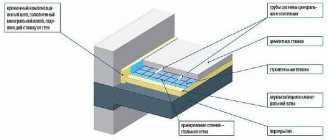
The essence of the collector
The main feature of a water heated floor is the coolant; the water gradually moves to the heating circuit and gives off part of its energy.
That is why the heating of the floor occurs with the release of heat to the air that is mixed inside the room, and it, as is known, is directed from the bottom up. A number of devices are responsible for supplying warm water to the circuit and intensity:
- the valve is considered the main one;
- a pump must be present;
- collector.
All control of water distribution is carried out using a flow meter. It is this device that plays the main role in the operation of the entire system.
All collectors are designed specifically for hot water, and they are also necessary to collect waste material. In the unit itself, the process of mixing hot water that comes from the source and return takes place.
Thanks to rotameters, there is a chance to ensure that the entire volume of water reaches the floors. Simply put, the equipment will independently control the heat in the water field.
Floor heating cannot do without a rotameter. The design includes a body made of plastic, but there are models made of brass. A float is placed inside any device. There is a flask with a scale.
We recommend: How can you make warm floors?
The float can move up and down and at the same time points to a certain division of the scale. Judging by it, it will be possible to judge the volume of coolant that circulates in the pipeline.
If we talk about theory, the system works without a device, but in this case the adjustment has to be done manually, relying on your own sensations.
The flow meter for the underfloor heating manifold plays an important role; if it is abandoned, the following problems will arise:
- the fact is that in the absence of a flow meter, some floor contours can be supplied with coolants, while the features of the room will not be taken into account;
- the energy consumption used to operate heating devices, for example, either gas or electricity, will be excessively increased.
Let's say you plan to simultaneously heat the bathroom and another room, for example, a bedroom. A gas-powered boiler will heat water for the bathroom and bedroom absolutely identically, that is, there will be one temperature regime.
It is important to install the equipment correctly; to do this, you need to screw the device itself into the collector socket. Fixation occurs due to the nut. When improving a heated floor, it is advisable to try to control the length of the heat pipeline of all circuits, without paying any attention to the configuration. This will simplify the adjustment of the system and it will still be possible to achieve normal temperature parameters.
But we must take into account that the bathroom is small in size, in order to heat it you need less water from the boiler, but more water is required to supply the bedroom. It is possible to compare the heat of each room, but only in this case will you need to use a flow meter.
If you use this device, the temperature will be set in the bathroom and bedroom for a comfortable stay there.
Having carefully assessed the principle of operation of this device, we can draw the following conclusions:
- the device can function completely autonomously, without the need to use any additional power sources;
- the main operating principle of the flow meter makes it possible to sufficiently consume the coolant for the circuit and further significantly reduce the energy costs of all heating devices;
- the design of the entire device is capable of providing control over the amount of water entering the pipes;
- the manifold, which is installed together with the flow meter, makes it much easier to control the operation of the entire system in general. Also, installation of the system is not complicated and does not require special maintenance.
We recommend: How to install heated floors in a toilet?
Working with Manifold Flow Meters
Hydraulic balancing of underfloor heating loops involves normalizing the flow in each coil. Depending on the length, different amounts of incoming coolant may be required so that when passing through the loop it cools exactly to the calculated value. The required flow is quantitatively determined as the ratio of the thermal load on the loop to the product of the heat capacity of water or other coolant and the temperature difference in the supply and return: G = Q / s * (t1 - t2).
You can often find recommendations to determine the coolant flow according to the performance of the circulation pump, that is, to divide its supply in proportion to the ratio of the lengths of the loops. Such advice should be avoided: in addition to the fact that it is quite difficult to calculate the length of each coil, one of the most important rules is violated - choosing equipment parameters based on the needs of the system, and not vice versa. Attempts to distribute flow in the described manner almost always lead to the fact that the flow in the loops differs significantly from the calculated values, which makes further adjustment of the system impossible.
Adjusting the flow with flow meters is quite simple. In some models, the throughput is changed by turning the body, in others - by rotating the rod with a special key. The scale on the flow meter body indicates the flow rate in liters per minute; you just need to set the float to the appropriate position. Almost always, when the capacity of one flow meter changes, the flow rate in the remaining loops changes, so the adjustment is carried out several times, sequentially calibrating each outlet. If such changes are particularly pronounced, this indicates a lack of capacity of the control valves through which the collector is connected, or that the performance of the circulation pump is too low.
How is balancing done?
Depending on the flowmeter model, after installation and pressure testing of the heating system, they are set to the initial “open” position. For devices that do not have a built-in valve with speed graduation, an additional valve is set to the “fully open” position, and the system is balanced after startup.
Standard assembly of the manifold group
In combined models, it is possible to preset the number of full valve revolutions. Each revolution reduces the clearance by a fixed amount.
First, the volume of coolant required for each circuit is calculated and its share is determined as a percentage relative to the total volume of coolant for the entire system. In accordance with these indicators, the initial position of the flowmeter valve head on each circuit is set.
The final adjustment is made during operation. At the same time, they are based on real temperature indicators and feelings of comfort.
Important! When tuning, you should change the parameters smoothly, since a decrease in the flow rate in one ring of the system will lead to an increase in flow in other rings.