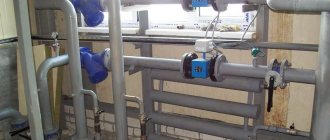
Automatic heat control system (SART)
TeleSystems LLC proposes the implementation of an automatic control system for heat consumption (SART) in order to ensure the rational use of thermal energy and create comfortable conditions for living and working.
Each of us has noticed more than once that during periods of warming, the radiators in the building remain as hot for a long time as in cold weather. Unfortunately, the centralized heating system in our country is characterized by inertia: correction of the coolant temperature at the heat source is carried out with a noticeable lag. Moreover, the centralized system is always focused on the average consumer, as a result of which in buildings located closer to the heat source, overestimated coolant parameters are always observed. In an effort to provide ourselves with comfortable living and working conditions, we open the windows, and the heat we pay for goes outside. And therefore, here lies the source of energy savings.
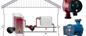
You can save on heat consumption by installing an automatic coolant temperature control system (CART) in the individual heating station of the building. It is designed to regulate heat consumption by increasing or decreasing the flow of coolant into the building, depending on its real needs at the moment.
Automation of the process of regulating the heat supply of MKD
The existing system of transportation and distribution of thermal energy is far from ideal. Its imperfection is especially acute during the off-season. It often happens that the weather outside is consistently warm, and the radiators stubbornly heat the already warm rooms. This situation is due to the fact that the only link in the chain of enterprises, communications and coolant supply devices that has the ability to influence the heat supply process is the boiler house or thermal power plant. But even they do not have the possibility of flexible regulation; they do not have mechanisms that allow them to instantly respond to weather changes.
The ideal option for regulating the heat supply in an apartment building would be a project in which, when implemented, it becomes possible to regulate the temperature of each room separately. This solution allows for individual metering of heat supply, which in turn allows residents not to pay for heat that simply escapes through open vents.
Individual metering of heat supply allows the consumer to independently regulate the amount of thermal energy consumed . This can be achieved by setting the temperature of rooms that are not in use lower, raising it as needed.
Heat supply can be regulated by turning off the taps on the radiators. In addition, you can entrust the regulation process to automation. Modern industry offers various devices that allow you to regulate the room temperature. The most common of them are radiator thermostats. These are devices consisting of a thermostatic head and a valve. The sensor measures the room temperature and controls the valve. Depending on the preliminary settings, the valve increases or decreases the flow of coolant, adjusting the heating level.
Thanks to the possibility of precise adjustment, this device allows you to regulate the microclimate inside the building, maintain a comfortable atmosphere, and save energy. There are different types of radiator thermostats. Most of them allow you to set the temperature value that the owner of the room wants to achieve. More complex models exist. Some of them allow you to set the temperature for different times of the day; for example, they can limit the heat supply during the day when there is no one in the apartment, and in the late afternoon they can warm the room to a comfortable level.
The main tasks of SART:
- Elimination of the supply of coolant to the facility with overestimated (“overheating”) and underestimated parameters, while the regulation of the coolant parameters depending on the outside air temperature occurs with minimal inertia - SART performs the correction instantly.
- Regulating the temperature of the coolant in the return pipeline of the heating network to eliminate the application of penalties by energy supply organizations for exceeding this temperature. SART allows you to limit the coolant intake from the network and re-enter it from the return pipeline into the heating system. And so on until his temperature reaches normal.
- Saving thermal energy by lowering the coolant temperature at night, as well as on weekends and holidays. For example, if a workshop operates in three shifts without days off, then this mode is not applicable, but if there is no staff in the workshop at night and on weekends (holidays), then it is possible to reduce the temperature of the coolant during this time.
- Maintaining a given temperature regime in the building using sensors located in control rooms. This will not save money, but will provide comfortable living and working conditions. The difficulty lies in selecting a control room for installing the sensor, taking into account that the temperature in it will affect the climate in the entire building. It is used, as a rule, for objects with a clearly defined control room, where it is necessary to ensure the greatest comfort with a variable schedule: cinemas, swimming pools, etc.
Also, the system developed by our specialists provides the technical ability to issue signals to a unified dispatch center when the regulated parameters go beyond the control limits. This significantly increases its reliability and minimizes the likelihood of system and equipment failure.
Benefits from implementing SART
The cost of creating a SART (design, installation and delivery to the ESO) by specialists of TeleSystems LLC, according to the price list, starts from 250 thousand rubles.
Our calculated average values of possible savings in thermal energy consumption using all algorithms of the SART module:
- application of weather control
16%, application of scheduled regulation
Total: total savings are about 38%.
In addition to savings and comfortable living conditions, the implementation of SART ensures balancing of the heating system, increases the service life of heating system equipment, increases the attractiveness of the house and ensures compliance with legislative requirements for energy saving.
Composition of the regulatory system
SART is a system of temperature sensors, a control valve, pumps, a controller and communication equipment (if remote control of the system is required). Using installed sensors, the temperature outside and inside the house, as well as the temperature in the supply and return pipelines, is analyzed. This data is transmitted to the control cabinet controller. The controller analyzes the sensor readings and issues a command to the control valve in accordance with a given schedule.
The control unit allows:
- set the temperature control mode for each day of the week, taking into account working and non-working hours;
- automatically maintain the specified mode for regulating the coolant supply;
- adjust the temperature regime and calendar when shifting working days and weekends;
- programmatically set the configuration of the heat control system from a set of standard schemes.
- facility supply line schedules;
- object return line schedules;
- hourly graphs of the regulator operating mode;
- normalized room temperature;
- standardized temperature at the boiler outlet;
- characteristics of valves and hydraulics; pump operating modes.
An automatic heat control system is installed on existing pipelines.
The cost of SART and its payback period are determined after the Customer fills out the questionnaire and processes it by the specialists of TeleSystems LLC. According to the experience of our company, residents’ investments pay off in 1 to 1.5 heating periods, while the service life of the equipment, if used correctly, is at least 15 years.
Our specialists have many years of experience in installing SART. We use reliable equipment from well-known manufacturers such as Danfoss, Wilo, Grundfoss, etc. Contact us and we will help you choose the best option for you. Preliminary examination is free.
Additionally, we recommend installing a module for commercial metering of consumed thermal energy in the heating station. Its installation will allow you to pay for real heat consumption, rather than calculated, and thus reduce heating costs.
Based on the experience of installing heat metering modules, the average savings during the heating season are:
- in residential brick buildings (taking into account the termination of payment for excess losses) - up to 40%;
- at social facilities (schools, kindergartens, hospitals, sanatoriums, etc.) - up to 40%;
- in residential panel buildings – up to 35%;
- in office buildings and administrative buildings – up to 25%;
- in industrial buildings (production workshops, warm warehouses, etc.) - up to 20%.
An integrated approach to energy saving
– Conducting energy surveys: from express surveys to in-depth energy surveys, from audits of products and technological processes to audits of a group of enterprises.
– Formation of energy saving programs both for an individual enterprise and for a region based on the results of energy surveys.
– Implementation of energy saving programs: from installing energy meters to renovating buildings.
A special place in the company’s product line is occupied by a number of complex products aimed at automating the accounting and management of energy resources based on the “Bee.Net” software developed by the company’s specialists.
© TeleSystems LLC Address: 620028, Ekaterinburg, st. Melnikova, 20 Tel./fax
Housing and communal services in Russia
Heating system adjustment
Any heating system, newly installed, repaired or reconstructed, or misregulated during long-term operation, requires thermal and hydraulic adjustment.
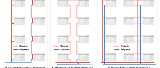
One of the main tasks of setting up a heating system is to distribute the coolant throughout the houses, and then among the risers and heating devices (hereinafter referred to as radiators) in proportion to their thermal loads.
Heating system calculation
The first stage of setup: calculation of the heating system , the purpose of which is to determine what coolant flows need to be passed through the inlet node of each house, and then through the risers and heating devices under the design conditions, that is:
- with calculated heat losses through the external fences (walls, windows, ceilings, floors) of the heated room;
- with installed radiators with designed heating surfaces;
- at the design temperature of the coolant in the supply pipeline;
- at the calculated values of water pressure in the supply and return pipelines at the outlets of the heat supply source,
Choosing a method for regulating coolant flow
The second stage of setup: choosing a method for regulating the coolant flow , which should flow into the heating system of each house, and installing the appropriate equipment..
The coolant flow is regulated in one of four ways or simultaneously by several of them, depending on specific conditions:
- Selecting the type and performance of the hydraulic elevator (the diameter of its nozzle) (see the article “Elevator unit”);
- Choosing the diameter of the throttle diaphragms and their installation location - on the supply or return pipeline (or on both pipelines) depending on the hydraulic mode required for the system (the professional slang name for a throttle diaphragm is “washer”, and the process of their installation is “washing”);
- Installation on risers, in addition to shut-off valves, additional balancing (control) valves or throttle diaphragms, allowing for balancing of the heating system (this method is effective, but is still of limited use);
- The choice of automatic devices for regulating the flow and temperature of the coolant.
Checking the correctness and efficiency of the heating system
The third stage of adjustment: checking the correctness and effectiveness of the adjustment performed and, if necessary, making additional adjustments.
The main indicators of the correct setup of the heating system are:
- compliance of actual water consumption with the calculated values in the supply and return pipelines of the house, in individual risers of the house and in individual radiators. These water flow rates can be determined either directly from the readings of the corresponding flow meters, or by a calculation method based on the results of measurements of three actual temperatures: coolant at the inlet and outlet of the building, in individual risers of the house and in individual radiators, and air temperature in the room (how to determine actual water flow through the radiator in your apartment, see the article “Heating malfunction in your apartment”).
An indicator of the correctness of the setup is the coefficient of relative water flow , which should be in the range of 0.9 - 1.15 (the calculated water flow is taken as one);
— compliance of the actual air temperature in the premises with standard (calculated) values. The average value of measured temperatures should not be lower than the calculated temperature by more than 0.5 °C or higher than the calculated temperature by more than 2 °C.
After installing or replacing elevator nozzles or throttle diaphragms on thermal inputs, the air temperature in at least 15% of the rooms should be checked.
If the coefficient of relative water flow differs from the norm by 0.9 - 1.15 or the average value of the measured air temperatures in the premises is lower than the calculated one by more than 0.5 °C or higher than the calculated one by more than 2 °C, a change must be made elevator nozzles and throttle diaphragms, as well as setting automatic temperature controllers.
The test results are documented and entered into the passport of the heating system and the building.
If dear colleagues are interested in more detailed information about setting up heating systems, you can use the following literature:
- SNiP 41-02-2003 Heating networks.
- Industry standard OST 36-68-82 1982 Heat networks. Regime adjustment of centralized heating systems
- Standard instructions for the technical operation of heating networks of municipal heat supply systems MDK 4-02.2001
- I. Manyuk Setup and operation of water heating networks. In M. Stroyizdat, 1988.
- E.Ya. Sokolov District heating and heating networks. M. Energoizdat, 1982.
Compiled by housing and communal services specialist Yuri Kalnin
Choosing a heat control system with maximum efficiency
In accordance with the requirements of regulatory documentation and Federal Law No. 261 “On Energy Saving...”, the installation of automatic weather control systems should become the norm, both for new construction projects and for existing buildings, since this is the main tool for heat supply management. Today, such systems, contrary to popular belief, are quite accessible to most consumers. They are functional, highly reliable and allow you to optimize the process of thermal energy consumption. The payback period for the installation of equipment is within one year.
The automatic heat control system (SART) allows you to reduce thermal energy consumption due to the following factors:
- Elimination of excess thermal energy (overheating) entering the building;
- Decrease in air temperature at night;
- Decrease in air temperature on holidays.
Integrated indicators of thermal energy savings from the use of SART installed in an individual heating point (IHP) of a building are presented in Fig. No. 1.
Fig.1 Total savings reach 27% or more*
*according to NPP Elekom LLC
The main elements of classical SART are shown in general form in Fig. No. 2.
Fig.2 Basic elements of SART in ITP*
*auxiliary elements are not shown
Purpose of the weather controller:
- Measurement of outside air and coolant temperatures;
- Control of the KZR valve depending on the established regulation programs (schedules);
- Data exchange with the server.
Purpose of the mixing pump:
- Ensuring constant coolant flow in the heating system;
- Ensuring variable coolant mixing.
Purpose of the KZR valve:
control of the supply of coolant from the heating network.
Purpose of temperature sensors: measuring coolant and outside air temperatures.
- Differential pressure regulator. The regulator is designed to maintain a constant pressure drop of the coolant and eliminates the negative impact of an unstable pressure drop of the heating network on the operation of the SART. The absence of a differential pressure regulator can lead to unstable operation of the system, reducing the economic effect and service life of the equipment.
- Room temperature sensor. The sensor is designed to monitor indoor air temperature.
- Data collection and control server. The server is designed for remote monitoring of equipment performance and correction of heating schedules based on readings from indoor air temperature sensors.
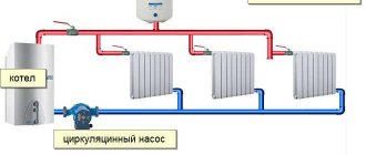
The principle of operation of the classical SART scheme is qualitative regulation, complemented by quantitative regulation. Qualitative regulation is a change in the temperature of the coolant entering the heating system of the building, and quantitative regulation is a change in the amount of coolant coming from the heating network. This process occurs in such a way that the amount of coolant supplied from the heating network changes, but the amount of coolant circulating in the heating system remains constant. Thus, the hydraulic mode of the building’s heating system is maintained and the temperature of the coolant entering the heating devices changes. Keeping the hydraulic mode constant is a necessary condition for uniform heating of the building and efficient operation of the heating system.
Physically, the control process occurs like this: the weather controller, in accordance with the individual control programs embedded in it and depending on the current temperatures of the outside air and coolant, supplies control actions to the KZR valve. When in motion, the shut-off element of the KZR valve reduces or increases the flow of network water from the heating network through the supply pipeline to the mixing unit. At the same time, due to the pump in the mixing unit, a proportional selection of coolant is carried out from the return pipeline and mixed into the supply pipeline, which, while maintaining the hydraulics of the heating system (the amount of coolant in the heating system), leads to the required changes in the temperature of the coolant entering the heating radiators. The process of reducing the temperature of the incoming coolant reduces the amount of thermal energy that is taken per unit time from the heating radiators, which leads to savings.
SART diagrams in ITP of buildings from different manufacturers may differ slightly, but in all schemes the main elements are: weather controller, pump, KZR valve, temperature sensors.
I would like to note that in conditions of the economic crisis, an increasing number of potential customers are becoming price sensitive. Consumers are beginning to look for alternative options with the least amount of equipment and cost. Sometimes along the way there is a mistaken desire to save money by installing a mixing pump. This approach is not justified for SART installed in ITP buildings.
What happens if you don't install a pump? And the following will happen: as a result of the operation of the KZR valve, the hydraulic pressure drop and, accordingly, the amount of coolant in the heating system will constantly change, which will inevitably lead to uneven heating of the building, inefficient operation of heating devices and the risk of stopping the coolant circulation. In addition, at negative outside temperatures, the heating system may “defrost”.
It’s also not worth saving on the quality of the weather controller, because... Modern controllers allow you to select a valve control schedule that, while maintaining comfortable conditions inside the facility, allows you to obtain significant amounts of thermal energy savings. This includes such effective heat management programs as: eliminating overheating; reducing consumption at night and on non-working days; elimination of overestimation of return water temperature; protection against “defrosting” of the heating system; correction of heating schedules based on indoor air temperature.
To summarize the above, I would like to note the importance of a professional approach to the selection of equipment for a weather automatic control system for heat consumption in a building’s ITP and once again emphasize that the minimum sufficient basic elements of such a system are: a pump, a valve, a weather controller and temperature sensors.
23 years of work experience, ISO 9001 quality system, licenses and certificates for the production and repair of measuring instruments, SRO approvals (design, installation, energy audit), accreditation certificate in the field of ensuring uniformity of measurements and recommendations from clients, including government agencies, municipal administrations, large industrial enterprises allow the ELECOM company to implement high-tech solutions for energy saving and increasing energy efficiency with an optimal price/quality ratio.
Starting and adjusting heating systems
Start the heating system. Before starting the heating system, an external inspection of the equipment is carried out, as a result of which compliance with the design of diameters, slopes, painting, thermal insulation and laying of pipelines, the type and number of heating devices, correct installation and serviceability of shut-off and control valves, mud tanks, elevators or mixing pumps, control and measuring equipment is established. devices, make-up pumps and other equipment, correct installation of heating devices.
The heating system is started only after washing and pressure testing, as well as checking the quality of work carried out on the system and the availability of working documents and documentation for the system and its equipment (passports, washing and testing reports, work diagrams, instructions for system equipment).
When turning on heating systems in populated areas on a large scale, it is recommended to quickly remove air from the systems in the following order of putting the systems into operation: with a flat and decreasing profile of the terrain from the heat source - in the direction from the source to the end consumers, and with an increasing profile of the terrain from the heat source - in direction from the end consumer to the source.
The commissioning of the heating system is a responsible event in the operation of the system, carried out in strict accordance with the schedule by a team of mechanics, divided into pairs, each of which performs operations when starting the system on 3-4 risers. When filling the system, all air collectors at the highest points must be open. If the pressure in the return pipeline is higher than the possible hydrostatic pressure in the heating system, the system is filled by smoothly opening the valve on the return pipeline so that the pressure decreases by no more than 0.03-0.5 MPa. If a water meter is installed on the return pipeline, then the system is filled through the bypass pipeline, and if it is absent, the water meter is removed and a pipe with a flange is installed in its place.
If the pressure in the return pipe is lower than the possible hydrostatic pressure in the heating system, then filling is carried out as follows.
In the absence of a pressure regulator, “upstream” - initially by supplying water from the return pipeline, and then from the supply pipeline through the suction line to the elevator into the return line, while filling is carried out slowly, monitoring the readings of the pressure gauges.
If there is a pressure regulator “upstream”, the system cannot be filled by the usual opening of the valve on the return pipeline: thus, if there is no water in the heating system and circulation in it, the regulator valve will be subject to a one-way force from the spring, trying to close the valve. In this case, to fill, it is necessary to carry out the following operations: open the air collectors in the upper part of the system and the valve on the return pipeline, loosen the valve spring, slightly open the valve on the supply pipeline and begin to slowly fill the system from the supply pipeline. In this case, it is necessary to observe the pressure gauge from the side of the heating system in the heating unit of the building. As soon as the pressures in front of the valve and behind the valve (on the return pipeline) are equal, the spring is tensioned. It is pulled until all air is removed from the system and water flows from the air collectors. After this, the air valves are closed and the spring is further tensioned so that the pressure in front of the regulator is equal to the height of the system plus 3-5 m.
When starting heating systems in winter, in addition to the above operations, it is necessary to take the following measures to prevent freezing of the system: 1) the heating system should be filled in separate sections (3-5 risers each) starting from the most distant sections from the input; filling and starting the risers and devices of the staircases can be carried out after filling and starting the main risers of the building's heating system; 2) risers and devices located in rooms that communicate with outside air (non-insulated rooms, rooms with no glazed windows, non-insulated passages, vestibules, etc.) must be turned off.
Heating systems with bottom wiring and horizontal single-pipe systems are filled with water from the supply pipeline of the heating network through both lines - direct and return. To do this, a jumper is installed in the thermal input. When filling a horizontal single-pipe system, first fill the riser and appliances of one floor with coolant, then the second, etc.
In a heating system with natural circulation, as a rule, all risers of the system are filled with water without dividing into parts. If there is sufficient pressure in the water supply, the heating system is filled with water from the water supply. If the pressure is insufficient, a pump is used to fill the system. Heating system regulation. An important condition for satisfactory operation of the heating system is achieving hydraulic balance. In an unbalanced system, some heating devices or circuits may be insufficiently supplied with coolant, while others receive it in excess.
After the heating system is put into operation, the consumption of thermal energy used for heating is determined. If the heat load does not meet the required values, the heating system is adjusted.
Heating systems of buildings and structures are adjusted to ensure the calculated indoor air temperatures. To do this, measure the temperature of the surfaces of heating devices using thermoelectric thermometers - temperature probes (thermocouples).
Regulation of heat transfer from heating systems can be carried out in two ways: 1) quality regulation, i.e. change in coolant temperature; 2) quantitative regulation, i.e. changing the amount of coolant.
High-quality regulation of central heating systems is carried out centrally at the boiler room or another heat source; quantitative control - directly on the heating system of the building.
Regulation of the heating system of a building begins with determining the coolant flow rates using water meters and flow meters installed at the heating point. In the absence of control and measuring instruments, regulation of the heating system is based on checking the compliance of actual water consumption with the calculated one. In this case, the calculated flow rate is understood as the water flow rate in the heating system, providing a given heat transfer (consumed thermal energy). The degree of compliance of the actual water consumption with the calculated one is determined by the temperature difference of the water in the system, while the actual water temperature in the heating network should not deviate from the calculated one by more than 2 °C.
If the difference is below the permissible level, this indicates an overestimated water flow and, accordingly, an overestimated diameter of the throttle diaphragm opening or nozzle at the entrance to the heating system. If the temperature difference is higher than the permissible value, then this indicates an underestimated water flow and, accordingly, an underestimated diameter of the throttle diaphragm or nozzle. In both cases, the new diameter of the elevator nozzle is determined.
If it is impossible to determine the actual pressure loss in the system, determining the new diameter of the throttle washer or nozzle can be carried out using the calculated pressure loss value. If, after replacing the nozzle or throttle washer, the internal temperature of the heated rooms differs by more than 2 °C compared to the calculated one, then it is necessary to change the diameter of the nozzle or throttle washer again. It should be noted that adjustment of building heating systems using washers is achieved only if the washers are designed and installed at the inputs of all buildings connected to the heating network.
The internal air temperature in the premises of buildings is measured 3-4 hours after the heating system of the building is turned on, subject to the temperature schedule of the water in the supply pipeline. The temperature is measured in at least 15% of heated rooms.
Due to the fact that heating systems, as a rule, are regulated not at the design outside temperature, but at relatively high outside temperatures at the beginning of the heating season, misadjustments occur in the heating system: - vertical - determined by the discrepancy between the heat transfer of heating devices on different floors and the required values; — horizontal — determined by an uneven change in heat transfer from heating devices on one floor.
Vertical misadjustment of two-pipe water heating systems with constant water flow occurs due to unequal changes in gravitational pressure in heating devices on different floors when the outside temperature changes. In single-pipe systems, vertical misadjustment occurs due to changes in water flow in the system. Reducing the flow rate leads to greater cooling of the water in the appliances on the upper floors; Consequently, very cooled water will flow into the lower devices, which will sharply reduce the heat transfer of the lower devices. To increase the heat transfer of lower devices, you can increase the temperature of the network water, but this will lead to increased heat transfer of the upper devices. In single-pipe systems with closing sections, the vertical misadjustment is, as a rule, less than in single-pipe flow-through systems.
Horizontal misalignment of heating systems occurs due to cooling of water in main pipelines and risers. Exceeding the heat transfer through the pipes above the calculated values leads to a decrease in the temperature of the water entering the individual risers. In the risers closest to the thermal input, the water temperature will be higher than in the risers distant from the thermal input.
Misadjustment of water heating systems is eliminated during the process of operational regulation of the systems.
During the entire regulation period, the temperature of the network water entering the heating system must be maintained constant.
Two-pipe heating systems are subject to the greatest misalignment. Such systems must be regulated at water temperatures in the system that correspond to the average outside temperature of the heating period, with adjustments for temperature differences in devices located on different floors: for devices on the upper floors - 1.5-3 ° C above normal, for devices on the lower floors floors - GS below normal.
Operational regulation of systems is carried out according to the required temperature difference in the thermal input by changing the amount of water entering the system according to the above requirements, depending on the type of systems and thermal input. Since the temperature difference is associated with water flow in an inversely proportional relationship, in order to increase the temperature difference to the required one, it is necessary to reduce the water flow by closing the valve at the inlet or, conversely, increase the flow rate at an increased temperature difference. The greater the flow of water through heating devices, the greater the speed of its movement, and therefore, the water in the device will cool less, the average temperature in the device will increase, which will cause its increased heat transfer. After completing the adjustment in the heating unit, they begin to adjust the individual risers of the system. In dead-end systems, adjustment is made using taps on the risers, throttling washers or balancing valves installed on the risers.
If there are only taps on the risers, then first make preliminary adjustments based on the rule: the closer the riser is located to the inlet, the more the tap should be closed, so that on the nearest riser the tap allows a minimum amount of water; on the farthest riser the tap should be fully open. After preliminary adjustment, check the heating of each riser and begin sequentially adjusting the risers, starting from the furthest one and ending with the one closest to the input.
If throttle washers are installed on the risers, then the distribution of water along the risers is checked according to the calculated temperature difference for the heating system. Having finished setting up the risers, they begin to regulate the heat transfer of heating devices by measuring the temperature difference at the inlet and outlet of water from the device. When regulating the system using temperature probes, a deviation from the calculated value of ±10% is allowed.
Balancing valves are pipeline throttling valves of variable hydraulic resistance, designed to ensure the calculated flow distribution along the elements of the pipeline network or to stabilize circulation pressures or temperatures in them. Currently, two types of balancing valves are used - manual and automatic.
Manual valves are used instead of throttling diaphragms (washers) to set up a heating system in which either there are no automatic control devices or they do not allow limiting the maximum (calculated) flow rate of the moved medium. The manual balancing valve is a valve-type throttling device. Through manual balancing valves, you can not only regulate the system, but also turn off its individual elements, and empty the system through special drain valves. Setting the valve to the required throughput is determined by the spindle lift height. Regulation using manual balancing valves is similar to regulation using throttle washers.
Automatic balancing valves are used to 1 maintain a constant pressure difference between the supply and return pipelines of the system, to ensure constant coolant flow or stabilize its temperature. The valves are installed on risers or horizontal branches of the heating system. If necessary, the balancing valve is equipped with additional devices that allow you to perform the following additional functions: turning off individual risers or branches of the system, measuring the pressure drop and determining the coolant flow, draining the coolant and filling the system, air release, pre-setting, regulation with an electric temperature sensor, regulation ( control) pressure difference. The automatic balancing valve is adjusted in accordance with the operating instructions using an adjusting screw, which allows you to change the flow area of the valve and, accordingly, the coolant flow.
In two-pipe systems, due to the influence of pressure, as a rule, the devices on the upper floors overheat. If there is no overheating on the lower floors, then reduce the heat transfer of the devices on the upper floors, reducing the flow area of the double adjustment valves. In the absence of such taps, throttle washers are installed in front of the devices, determining the diameter from the condition of the calculated water flow passing through them and taking the pressure loss in the device to be equal to 0.05 m, or the heating surface of the heating device is reduced. If appliances are overheated on the upper floors and underheated on the lower floors, use double adjustment valves to reduce the flow area on the upper floors and increase it on the lower floors. If there are no taps on the return pipeline in the riser between overheated and underheated floors, it is allowed to install a throttle washer.
If the devices on the upper floors are overheated and the lower ones are underheated in single-pipe systems with closing sections, the following measures can be taken: install throttling washers in front of the devices on the upper floors; reduce the heating surface of devices; dismantle the closing sections of the devices on the lower floors (1st and 2nd) and, if necessary, increase the diameters of the connections.
With uniform underheating of the heating devices on the upper floors and simultaneous overheating of the devices on the lower floors, the mixing coefficient of the elevator is reduced.
The water flow in heating devices of a single-pipe system is regulated by the temperature difference of the water in the devices.
If there are no taps on the risers, then using taps on the devices, you can simultaneously redistribute water flows both over individual risers and across individual devices. The degree of opening of the taps during regulation increases as the devices move away from the thermal input.
In systems with top wiring, in addition, the degree of opening of taps within the riser decreases with the movement of water from the upper floor to the bottom, but in systems with bottom wiring it is the same.
In two-pipe heating systems, the uniformity of heating of devices increases with increasing water flow in the system. For single-pipe heating systems, it is not recommended to significantly increase the water flow in the system compared to the calculated one, as this can lead to floor-by-floor misadjustment of the system.
Regulating a dead-end system requires significant labor and time, since it is carried out in several stages, gradually bringing the heat transfer of devices closer to the required one.
In a two-pipe system with overhead distribution and a parallel movement of water, where the length of all circulation rings is approximately the same, the difference in heating of the devices can only be caused by the additional natural pressure (pressure) arising from the devices on the upper floors. To do this, during commissioning, close the taps on the appliances on the upper floors, and the degree of closing of the taps on the appliances on the same floor should be the same, since all risers are in equal conditions. After this, the heat transfer of the devices is finally adjusted.
In systems with lower distribution and associated movement of water, the additional natural pressure arising from the devices on the upper floors has little effect on the operation of the underlying devices due to the large length of the circulation ring. Therefore, in such systems only minor unevenness in the heating of individual devices is possible, which can be easily eliminated by regulation.
In vertical single-pipe systems with associated water movement, all heating devices and risers are in equal conditions, and regulation of such systems is not difficult.
Operational regulation of heating systems with natural circulation is the simplest, since in such systems there are usually no completely unheated devices.
Before making adjustments, the taps on all risers and appliances must be fully open. Uneven heating can be eliminated by adjusting the taps.
The water temperature during adjustment should be maintained within 50-60°C.
After adjusting the system, the temperature in the boilers of the local heating system is brought to 90°C and at this temperature the heating of the devices is checked again.
Under operating conditions, no matter how well the heating system is regulated, the actual air temperature in the rooms may be different. A reliable indicator of normal heat transfer from heating devices is the temperature of the coolant in the return risers. A low temperature indicates that the heating system is not receiving enough of the required amount of coolant from the heating network or its temperature is low.
An increased temperature indicates an excess consumption of coolant compared to the calculated value or the arrival of coolant with a temperature higher than normal according to the temperature schedule.
Read more: Organization of labor in construction Ventilation Regulatory and design documentation Labor protection during repair work Maintenance of building structures Cost and profitability in construction Technical and tariff regulation Organization of construction management in the USSR Housing construction in the Soviet Union Equipment and installation of ventilation and air conditioning systems
- Everything is very well and detailed described. Thank you for helping me prepare properly.
— Igor · Jan 28, 02:15 ·
Weather-compensated automation with shut-off valve and circulation pump.
And finally, the last type of automation for maintaining the temperature in apartments of residential buildings, depending on the temperature outside, is weather-dependent automation with a shut-off and control valve and a circulation pump.
Let's look at the principle of operation of this automatic temperature control system in an apartment, or rather, in an entire apartment building.
Here, temperature control in the heating system occurs by changing the valve capacity and, as in the previous scheme, mixing returned (return) network water from a residential building using a circulation pump, now installed on the return pipeline of the heating system. In principle, where the network or circulation pump will be installed is generally unimportant; it’s just that for a two-way valve such a scheme is still preferable due to its design features.
During the regulation process, the controller also periodically polls the coolant temperature sensors in the heating system of the house, indoor air sensors (if installed) and an outdoor air sensor. After processing the received information, the controller generates an output control signal to open or close the actuator of the two-way valve, and the value of opening or closing the flow area of the control valve changes accordingly. In the absence of an indoor air sensor, the main priority of regulation is also to maintain the temperature in the apartments according to the temperature schedule.
There is only one drawback of control schemes with valves - loss of electricity. For more information about the advantages and disadvantages of weather-dependent automation, see the article on weather control with a control elevator. The advantage of weather control schemes with valves over a control elevator is usually called the depth of regulation, although in our opinion such an advantage is controversial and can easily turn into a disadvantage if, for example, the ITP has a thermal energy metering unit, and its measurement limits are worse than the operating limits of automatic weather control. After installing automatic weather control without agreement with the energy supply organization, such a heating system can legally be recognized as non-commercial, which means that instead of saving, you will again receive payment for heat according to the standard.
- insufficient pressure at the inlet to the ITP, less than 0.07 mPa
- excessive resistance of the internal heating system of the house, more than 5 m.w.c.
- installation of automatic control valves on heating devices and risers, for example
- use of an independent heating system through heat exchangers.
I would also like to warn residents who are especially concerned about saving money that weather-compensated automation circuits with mixing valves cannot be used without a pump or with the pump turned off . In the operating mode with the pump turned off, the pumping of coolant through the heating devices sharply decreases; the difference in temperatures between the temperatures in the heating devices of different apartments sometimes reaches 45 degrees, instead of the twelve recommended for the economical mode of operation of weather-compensated automation. And most importantly, due to the lack of mixing in cold weather, the temperature in the heating devices of the first apartments along the route can reach 115 degrees or more, which will inevitably lead to the failure of modern polypropylene pipes , as well as burns from accidental touching of the heating devices - this is at a minimum. At the same time, the residents of the last apartments along the coolant path will sit in the cold.
This is the savings, and everything will be OK according to the instruments. And most importantly, if the check valve on the jumper between the direct and return pipelines fails, not only your home, but the entire area may be left without heat. The coolant will not go to the apartments, but will return back to the boiler room.
We examined possible options for schematic solutions for implementing weather-dependent automation in the control framework of multi-storey residential buildings. In any case, the decision to choose one or another weather-dependent temperature control scheme in the apartments of a residential building, and most importantly the selection of equipment, should be entrusted to specialists. You, as residents, should have your say only when choosing a design organization and the type of equipment - domestic or imported. The price depends on this.
All about the prices for design work, purchased equipment and installation and adjustment of automatic weather control in apartments of residential buildings on the next page.
In order to install a heat saving system in your home, you need:
Application
Survey
Visit of a specialist to the site and commercial offer - free of charge
Agreement
We carry out major and current repairs
Project
We develop an individual project. Approval from supervisory authorities
Installation
In any season. Quality assurance. Right on time.
Commissioning
We carry out commissioning work. Setting the optimal heat consumption mode at home.
In the period from 2013 to 2021, existing heating units were retrofitted with weather-dependent automatic heating and maintaining the set hot water temperature. The heating and hot water systems are equipped with 2-circuit ART-05 regulators, control valves with electric drives and circulation pumps.
Apartment buildings, administrative and industrial buildings, as well as institutions of the Department of Culture of the Vladimir Region were retrofitted with weather-dependent automation.
The average monthly result of heat savings with proportional heating control was 20%. At the same time, the problem of uniform heating of heating devices throughout the house and the absence of overheating was solved.
By agreement with the customer, it is possible to establish a daily schedule for regulating the temperature of heating and hot water for additional savings and comfort for residents of the apartment building.
Adjusting the heating temperature in the heating unit of an apartment building
In Russia, the central heating system of an apartment building is usually used, the coolant is supplied from a city boiler house or thermal power plant. At the same time, water circuits are arranged according to different schemes, since they can be single-pipe or double-pipe. Typically, heat consumers are of little interest in such nuances, but if it is necessary to repair an apartment and replace old batteries with new modern heating radiators, it is advisable for residential property owners to understand such subtleties.
The cost of autonomous heating in an apartment building is quite high, so it is preferable to commission one powerful boiler house that can provide heat and hot water to a residential neighborhood.
Through main pipelines, coolant from the central boiler room is supplied to the heating unit of an apartment building and is further distributed among the apartments. In this case, additional adjustment of the degree of hot water supply is carried out directly at the heating point, for which circular pumps are used. This method of supplying coolant to the end consumer is called independent (more details: “Central heating is both pros and cons”).
In addition, dependent heating systems are used in apartment buildings. In this case, the coolant is transported to apartment radiators without additional distribution directly from the thermal power plant. In this case, the water temperature is determined regardless of whether it is supplied through a distribution point or directly to consumers.
Types of heating systems in an apartment building can be open or closed (for more details: “Open and closed heating systems - advantages and disadvantages in comparison”).
In the latter option, the coolant from the thermal power plant or central boiler room, after entering the distribution point, is supplied separately to heating radiators and to the hot water supply. In open systems, such a separation is not provided for by the design and heated water for the needs of residents is supplied from the main pipe, so consumers are left without hot water supply outside the heating season, which causes many complaints about utility services.