The defining task when designing an autonomous heating system is the uniform distribution of the coolant. This task in the heat supply system is performed by a control and regulation unit - the distribution manifold.
The uninterrupted operation and reliability of the heating circuit largely depends on the correct choice of device, high-quality installation and connection. If you want to install a heating distribution manifold with your own hands, then you need to carry out calculations and design the wiring in advance.
We will help you resolve these issues. In the article, we examined the design of the collector group, identified the pros and cons of a heating system with a comb, and described the rules for the design and installation of a distribution unit.
The material is supplemented with practical advice on selecting components, assembling and connecting the collector to the heating system.
The role of the collector in heating
When arranging a water pumping unit, you must adhere to the rule: the total sum of the diameters of all branches should not be greater than the diameter of the supply main.
Let's apply this law to the heating system, but it will look like this: a boiler outlet fitting with a diameter of 1 inch is allowed for use in a double-circuit system with pipes with a diameter of ½ inch.
For a house with a small cubic capacity that is heated exclusively by radiators, this kind of system is considered productive.
For utility rooms, it will be enough to set the temperature to 10-15 °C; for living rooms, a temperature of up to 23 °C will be comfortable; in underfloor heating circuits – no more than 37 °C, otherwise the main coating may be deformed.
In practice, a private cottage is equipped with a more modernized heating circuit, where additional circuits are installed:
- heated floor system;
- heating of several floors;
- utility rooms, etc.
When a branch is connected, the level of operating pressure in the circuits becomes insufficient for high-quality heating of all radiators, respectively, and the comfortable atmosphere will be disrupted.
In this case, a balancing unit is installed for a branched heating main using a distribution manifold. Using this method, it is possible to compensate for the cooling of the heated coolant, which is typical of traditional one- and two-pipe schemes.
By means of equipment and shut-off valves, the required coolant temperature indicators are adjusted for each of the lines.
Heating distribution manifold - “comb”
Nowadays, many people, when arranging a heating system, are increasingly less likely to pay attention to standard one-pipe or two-pipe schemes. Most people choose a distribution manifold (or “comb”). With its help, through one wiring, you can create the desired temperature for each individual room. In addition, this scheme implies significant savings in fuel resources.
Main characteristics of the collector system
The main difference between the collector and standard linear method of redistribution of the coolant is the division of flows into several channels independent of each other. Various modifications of collector installations can be used, differing in configuration and size range.
The collector heating circuit is often called radiant. This is due to the design features of the comb. When examining the device from the top point, you will notice that the pipelines extending from it resemble an image of sun rays
The design of the welded manifold is quite simple. The required number of pipes is connected to the comb, which is a round or square pipe, which, in turn, are connected to individual lines of the heating circuit. The collector installation itself is interfaced with the main pipeline.
Shut-off valves are also installed, through which the volume and temperature of the heated liquid in each of the circuits is regulated.
A manifold group, complete with all the necessary parts, can be purchased ready-made or assembled independently, which will significantly reduce the cost estimate when designing heating
The positive aspects of operating a heating system based on a distribution manifold are the following:
- The centralized distribution of the hydraulic circuit and temperature indicators occurs evenly. The simplest model of a two- or four-circuit ring comb can balance the indicators quite effectively.
- Regulation of operating modes of the heating main . The process is reproduced due to the presence of special mechanisms - flow meters, mixing unit, shut-off and control valves and thermostats. However, their installation requires correct calculations.
- Ease of maintenance . The need for preventive or repair measures does not require shutting down the entire heating network. Due to the sliding pipeline fittings mounted on each individual circuit, you can easily shut off the coolant flow in the required area.
However, there are also disadvantages to such a system. First of all, pipe consumption increases. Compensation for hydraulic losses is carried out by installing a circulation pump. It must be installed on all collector groups. In addition, this solution is only relevant in closed-type heating systems.
Modifications of collector units
Before you begin assembling the collector assembly, it is necessary to determine its functional load. The equipment can be installed in several sections of the heating main. Based on this, the necessary equipment, dimensions and level of automation of the work cycle are selected.
In fact, for the full operation of such a node, two devices are needed. Using a comb, the coolant is distributed along the contours of the central supply pipeline. The return collector channel is represented by a collection mechanism and the point of departure of the cooled liquid into the boiler.
The collector heating circuit is selected based on the calculation of the required functionality and installation location. The choice of material for making the device does not affect the number of significant mechanisms
Installation of a homemade distribution group may be required when installing water-heated floors or for preparing standard heating with radiators.
Distinctive features of both options are their sizes and components:
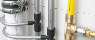
- Boiler room . The welded manifold group is made of pipes with a diameter of up to 100 mm. A circulation pump and shut-off valves are installed on the supply side. The return ring is equipped with shut-off ball valves.
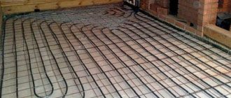
- Warm floor system . Similar equipment is present in this mixing unit. With its help, it is possible to significantly save on coolant consumption, especially if additional flow meters are installed. Read more about the mixing unit in a heated floor system in this article.
Each of these solutions provides an individual installation scheme. Correct installation of all elements can be carried out only after detailed calculations of all operating point parameters.
The comb can be made of the same material as the pipeline. If it is different, adapters will be used to connect the collector
There are also differences in the required number of circulation pumps. In the boiler room, each line is equipped with this device. For heated floors, only one installation is provided.
Heating manifold with hydraulic arrow.
Heating distribution manifold with hydraulic arrow
There are two types of collector circuits:
- Without additional circulation pumps and without hydraulic arrow.
- With the presence of the listed units.
Heating distribution manifold
The second option has much greater functionality and serves to create different temperature conditions in each individual circuit (for example: radiators - from 45 to 65 degrees; warm water floor - from 30 to 45 degrees; tap water about 80 degrees). In such a scheme, an important element is used - a hydraulic arrow.
Hydraulic gun in the “comb”
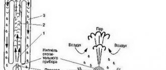
The hydraulic arrow is a piece of pipe closed on both sides and 2 pairs of pipes connected to it. The first two pipes connect this element to the boiler. A couple of other pipes are connected to the combs.
The main function of the hydraulic arrow is to create a hydraulic obstacle.
Mixing units with 3-way valves that regulate temperature are installed on the distribution manifold. A separate outlet pipe has its own pump, which ensures the required temperature conditions for this circuit.
If you install a network without additional pumps and hydraulic arrows, the temperature of all radiators will be equal and its adjustment will be impossible. There is only one circulation pump in the system. Due to differences in the length of individual circuits, it is better to install balancing valves in the manifold to approximately regulate the amount of coolant entering the individual batteries.
Distribution node design
There is simply no universal scheme for a radiant heating project. Each case is individual, which is why the unit is equipped with the necessary devices privately. However, it is worth familiarizing yourself with the general recommendations and rules.
Rules for installing the comb
Installation of the collector is not possible in an apartment. However, there is an exception to the rule - in some houses, when all communications are installed, additional valves are installed, through which the heating circuits are connected. This device allows for individual wiring of the collector.
The beam scheme is not suitable for city apartments in multi-storey buildings, because the riser is common to all premises (+)
The schematic arrangement of the heating should be designed in such a way that the location of the Mayevsky tap is on the comb. This option is considered optimal, because over time, accumulated air will need to be released from the circuits.
Features of the beam group
The radial wiring group has many nuances, but some of them are also typical for heating of other modifications.
Features of the comb system:
- The circuit must include a compensation tank with a volume of more than 10% of the total volume of the coolant.
- The optimal location of the expansion tank is on the return pipeline in front of the circulation pump, since the temperature regime is lower here.
- If a thermo-hydraulic distribution is used, the circuit is designed so that the tank is located in front of the main pump, which is responsible for the forced movement of water in the boiler piping.
- The circulation pump is installed in a strictly horizontal position. If you do not adhere to this rule, at the first air lock, the device will lose cooling and lubricant.
The distribution group can be assembled from various materials: polypropylene or metal. The selection is made based on work skills and the availability of tools for connecting parts.
The optimal heating temperature for radiators in a private cottage is 55-75 °C, pressure up to 1.5 atm. The operating mode of the warm floor circuit warms up to 40 °C. Based on these characteristics, the degree of stability of the pipes is selected
The process of selecting pipes for installing a distribution group is also considered important.
The main factors taken into account when choosing contour elements:
- Purchase of pipes only in coils . Due to this, connections are not made in the wiring installed under the concrete screed.
- Heat resistance and tensile strength must be determined individually based on the technical data of the heating system.
Due to the predictability of the operating characteristics of autonomous heating, polypropylene pipes can be used. They do not have unwanted connections and are sold in continuous 200 m lines.
The material is heat-resistant and can withstand temperatures up to 95°C with a permissible burst pressure of 10 kg/1 cm2.
Stainless steel pipe is highly flexible. The bend radius can be equal to the diameter of the product. Installation is carried out according to the following scheme: the pipe must be directed into the fitting and secured with a nut
For a multi-story building, it is preferable to choose a corrugated pipe made of stainless steel.
This material shows excellent technical capabilities to cope with such a load:
- heated coolant up to 100 °C, which is more than enough for the heating circuit;
- pressure up to 15 atm;
- fracture pressure up to 210 kg/1 cm2.
Fittings designed for polypropylene can be plastic or made of brass. The fitting connection is equipped with a locking ring, which is threaded onto the pipeline.
An important characteristic of polypropylene pipes is the memory of mechanical processing, which results in plastic deformation of the substance.
For example, when stretching pipes with an extender and installing a fitting into the connector, after a certain time the pipe will return to its previous state and crimp the part. The contact can be secured with a locking ring.
Heating manifold calculation
Initially, to manufacture a thermohydraulic comb, you will need to calculate its main parameters - length, cross-sectional diameter of the pipes and the number of branches of the heating main. You can calculate these characteristics yourself or use special software.
The hydraulic separator will fully perform its functions only if the rule of three diameters is observed. The law is as follows: the diameter of the mounted hydraulic arrow must be three times greater than this parameter for the pipes (+)
The hydraulic balance of the structure is the main condition that must be met. Applying the rule of three diameters for a hydraulic separator, it is necessary to perform the following action - sum up the cross-sectional diameter of the connected circuits.
As a result, we get an amount equal to the diameter of the main pipe connected to the supply line. Using this principle reduces the likelihood of imbalance of the entire heating system.
A special cabinet or housing is used as a place for the distribution unit. When arranging the system, it is necessary to adhere to the permissible minimum distance between two heat-conducting input and output lines - 6 diameters.
All calculations of the thermohydraulic comb design are based on three important rules: maintaining the correct distance between the incoming and outgoing lines, the cross section of the comb and the distance between the contours is equal to three diameters (+)
The issue of correct selection of the circulation pump performance is also relevant. To do this, it is necessary to calculate the specific rate of water consumption of the system and, based on the results, select a pump.
If the circuit is complicated by several combs, the calculation is performed for each individual circuit and in general for the entire system.
Self-assembly of equipment can be carried out using a pipe with any type of cross-section. This aspect does not affect the operation of the device and does not increase local losses. They will be compensated by the circulation pump.
Do-it-yourself heating manifold for polypropylene pipes: we explain the essence
The defining task when designing an autonomous heating system is the uniform distribution of the coolant. The complex of thermal engineering measures for organizing not only a productive, but also a reliable heating line includes the arrangement of such a control and regulatory unit.
If you wish and follow the nuances, you can assemble a heating distribution manifold with your own hands or simply pay for a ready-made option.
The role of the collector in heating
When arranging a water pumping unit, you must adhere to the rule: the total sum of the diameters of all branches should not be greater than the diameter of the supply main.
Let's apply this law to the heating system, but it will look like this: a boiler outlet fitting with a diameter of 1 inch is allowed for use in a double-circuit system with pipes with a diameter of ½ inch.
For a house with a small cubic capacity that is heated exclusively by radiators, this kind of system is considered productive.
For utility rooms, it will be enough to set the temperature to 10-15 °C; for living rooms, a temperature of up to 23 °C will be comfortable; in underfloor heating circuits – no more than 37 °C, otherwise the main coating may be deformed.
In practice, a private cottage is equipped with a more modernized heating circuit, where additional circuits are installed:
- heated floor system;
- heating of several floors;
- utility rooms, etc.
When a branch is connected, the level of operating pressure in the circuits becomes insufficient for high-quality heating of all radiators, respectively, and the comfortable atmosphere will be disrupted.
In this case, a balancing unit is installed for a branched heating main using a distribution manifold. Using this method, it is possible to compensate for the cooling of the heated coolant, which is typical of traditional one- and two-pipe schemes.
By means of equipment and shut-off valves, the required coolant temperature indicators are adjusted for each of the lines.
Main characteristics of the collector system
The main difference between the collector and standard linear method of redistribution of the coolant is the division of flows into several channels independent of each other. Various modifications of collector installations can be used, differing in configuration and size range.
The collector heating circuit is often called radiant. This is due to the design features of the comb. When examining the device from the top point, you will notice that the pipelines extending from it resemble an image of sun rays
The design of the welded manifold is quite simple. The required number of pipes is connected to the comb, which is a round or square pipe, which, in turn, are connected to individual lines of the heating circuit. The collector installation itself is interfaced with the main pipeline.
Shut-off valves are also installed, through which the volume and temperature of the heated liquid in each of the circuits is regulated.
A manifold group, complete with all the necessary parts, can be purchased ready-made or assembled independently, which will significantly reduce the cost estimate when designing heating
The positive aspects of operating a heating system based on a distribution manifold are the following:
- The centralized distribution of the hydraulic circuit and temperature indicators occurs evenly. The simplest model of a two- or four-circuit ring comb can balance the indicators quite effectively.
- Regulation of heating main operating modes. The process is reproduced due to the presence of special mechanisms - flow meters, mixing unit, shut-off and control valves and thermostats. However, their installation requires correct calculations.
- Ease of maintenance. The need for preventive or repair measures does not require shutting down the entire heating network. Due to the sliding pipeline fittings mounted on each individual circuit, you can easily shut off the coolant flow in the required area.
However, there are also disadvantages to such a system. First of all, pipe consumption increases. Compensation for hydraulic losses is carried out by installing a circulation pump. It must be installed on all collector groups. In addition, this solution is only relevant in closed-type heating systems.
Modifications of collector units
Before you begin assembling the collector assembly, it is necessary to determine its functional load. The equipment can be installed in several sections of the heating main. Based on this, the necessary equipment, dimensions and level of automation of the work cycle are selected.
In fact, for the full operation of such a node, two devices are needed. Using a comb, the coolant is distributed along the contours of the central supply pipeline. The return collector channel is represented by a collection mechanism and the point of departure of the cooled liquid into the boiler.
The collector heating circuit is selected based on the calculation of the required functionality and installation location. The choice of material for making the device does not affect the number of significant mechanisms
Installation of a homemade distribution group may be required when installing water-heated floors or for preparing standard heating with radiators.
Distinctive features of both options are their sizes and components:
- Boiler room . The welded manifold group is made of pipes with a diameter of up to 100 mm. A circulation pump and shut-off valves are installed on the supply side. The return ring is equipped with shut-off ball valves.
- Warm floor system . Similar equipment is present in this mixing unit. With its help, it is possible to significantly save on coolant consumption, especially if additional flow meters are installed.
Each of these solutions provides an individual installation scheme. Correct installation of all elements can be carried out only after detailed calculations of all operating point parameters.
The comb can be made of the same material as the pipeline. If it is different, adapters will be used to connect the collector
There are also differences in the required number of circulation pumps. In the boiler room, each line is equipped with this device. For heated floors, only one installation is provided.
Distribution node design
There is simply no universal scheme for a radiant heating project. Each case is individual, which is why the unit is equipped with the necessary devices privately. However, it is worth familiarizing yourself with the general recommendations and rules.
Rules for installing the comb
Installation of the collector is not possible in an apartment. However, there is an exception to the rule - in some houses, when all communications are installed, additional valves are installed, through which the heating circuits are connected. This device allows for individual wiring of the collector.
The radial scheme is not suitable for city apartments in multi-storey buildings, since the riser is common to all premises
The schematic arrangement of the heating should be designed in such a way that the location of the Mayevsky tap is on the comb. This option is considered optimal, because over time, accumulated air will need to be released from the circuits.
Features of the beam group
The radial wiring group has many features, but some of them are also typical for heating of another modification:
- The circuit must include a compensation tank with a volume of more than 10% of the total volume of the coolant.
- The optimal location of the expansion tank is on the return pipeline in front of the circulation pump, since the temperature regime is lower here.
- If a thermo-hydraulic distribution is used, the circuit is designed so that the tank is located in front of the main pump, which is responsible for the forced movement of water in the boiler piping.
- The circulation pump is installed in a strictly horizontal position. If you do not adhere to this rule, at the first air lock, the device will lose cooling and lubricant.
The distribution group can be assembled from various materials: polypropylene or metal. The selection is made based on work skills and the availability of tools for connecting parts.
The optimal heating temperature for radiators in a private cottage is 55-75 °C, pressure up to 1.5 atm. The operating mode of the warm floor circuit warms up to 40 °C. Based on these characteristics, the degree of stability of the pipes is selected
The process of selecting pipes for installing a distribution group is also considered important. The main factors taken into account when choosing contour elements:
- Purchase pipes only as a single element - in coils. Due to this, connections are not made in the wiring installed under the concrete screed.
- Heat resistance and tensile strength must be determined individually based on the technical data of the heating system.
Due to the predictability of the operating characteristics of autonomous heating, polypropylene pipes can be used. They do not have unwanted connections and are sold in continuous 200 m lines.
The material is heat-resistant and can withstand temperatures up to 95 °C with a permissible burst pressure of 10 kg/1 cm2.
Stainless steel pipe is highly flexible. The bend radius can be equal to the diameter of the product. Installation is carried out according to the following scheme: the pipe must be directed into the fitting and secured with a nut
For a multi-story building, it is preferable to choose a corrugated pipe made of stainless steel. This material shows excellent technical capabilities to cope with such a load:
- heated coolant up to 100 °C, which is more than enough for the heating circuit;
- pressure up to 15 atm;
- fracture pressure up to 210 kg/1 cm2.
Fittings designed for polypropylene can be plastic or made of brass. The fitting connection is equipped with a locking ring, which is threaded onto the pipeline.
An important characteristic of polypropylene pipes is the memory of mechanical processing, which results in plastic deformation of the substance.
For example, when stretching pipes with an extender and installing a fitting into the connector, after a certain time the pipe will return to its previous state and crimp the part. The contact can be secured with a locking ring.
Heating manifold calculation
Initially, to manufacture a thermohydraulic comb, you will need to calculate its main parameters - length, cross-sectional diameter of the pipes and the number of branches of the heating main. You can calculate these characteristics yourself or use special software.
The hydraulic separator will fully perform its functions only if the rule of three diameters is observed. The law is as follows: the diameter of the mounted hydraulic arrow must be three times greater than this parameter for the pipes
The hydraulic balance of the structure is the main condition that must be met. Applying the rule of three diameters for a hydraulic separator, it is necessary to perform the following action - sum up the cross-sectional diameter of the connected circuits.
As a result, we get an amount equal to the diameter of the main pipe connected to the supply line. Using this principle reduces the likelihood of imbalance of the entire heating system.
A special cabinet or housing is used as a place for the distribution unit. When arranging the system, it is necessary to adhere to the permissible minimum distance between two heat-conducting input and output lines - 6 diameters.
All calculations of the thermohydraulic comb design involve following important rules: maintain the correct distance between the incoming and outgoing lines, make sure that the cross section of the comb and the distance between the circuits are equal to three diameters
The issue of correct selection of the circulation pump performance is also relevant. To do this, it is necessary to calculate the specific rate of water consumption of the system and, based on the results, select a pump. If the circuit is complicated by several combs, the calculation is performed for each individual circuit and in general for the entire system.
Self-assembly of equipment can be carried out using a pipe with any type of cross-section. This aspect does not affect the operation of the device and does not increase local losses. They will be compensated by the circulation pump.
Rules for selecting components
Having completed all the calculations, the next step is to select the required set of mechanisms. The simplest set consists of shut-off valves. However, with such a device it is difficult to regulate the power of individual heating lines.
To solve this problem, crane axle boxes are installed on the feed comb, through which smooth adjustment is possible. Rotameters are mounted on the return manifold.
The collector parameters must be sufficient for convenient access to shut-off and control valves. The average range between the contours is 100-150 mm, the center distance between the feed and return combs is 250-300 mm
For warm water floors, the configuration scheme will be different. For assembly you will need the following elements:
- Shut-off and control valve. Installation is carried out on connecting pipes. With the help of this fittings, the flow of coolant is completely or partially stopped. It is recommended to use automatic modification.
- Rotameters. Such elements are mounted on the return collector. They perform a similar function as the previous element, only in the return pipeline.
- Mixing unit. By mixing hot and cold water flows, the specified heating operating mode is optimized.
The manifold kit is necessarily equipped with a safety group headed by a pressure gauge, air valve, thermostat and circulation pump. It can be supplemented with servo drives, the control of which is reproduced through the control electrical unit. Thus, the operation of the system can be automated.
Subtleties of self-assembly
Before manufacturing the collector, it is necessary to draw up a diagram showing the location of all the elements of the assembly. It is better to choose steel pipes with a square cross-section as the manufacturing material. This type is easy to process, which significantly reduces labor costs for installing pipes.
Manifolds made of profile pipes are used in the heating circuit of objects with a large number of circuits and a hydraulic separator. Square pipe parameters – 80*80 or 100*100 mm
The step-by-step process for producing a prefabricated distribution structure is as follows:
- Marking and cutting of the main body. According to the design diagram, it is necessary to mark the profile pipe. Using a gas cutter, holes are made in the marked areas.
- Preparing connections. The pipes are threaded using a die.
- Staffing. Next, the prepared pipe sections are welded to the body. Their fixation must be done by tack spot welding. Then, during the main welding, the workpieces are welded along the edges.
- Fastening elements. Brackets for fastening are welded to the block.
- Cleaning and finishing. After cleaning, the body is primed and coated with heat-resistant paint for metal products. The supply and return circuits are painted in two different colors for ease of identification.
If polypropylene pipes are used for production, you should pay attention to the presence of a reinforcing layer in them. In its absence, the plastic structure may be subject to deformation due to the current temperature conditions.
For those who do not have special tools, you can assemble a comb from separate ready-made elements. It is better to select components from one company.
Installing a comb in the heating system
The primary task is to check the distribution manifold for tight connections. The installation is implemented according to the design scheme. Depending on the material used to manufacture the main unit, the connection conditions are determined.
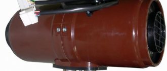
In complex systems where there are many circuits for various purposes, it is necessary to install a vertical pipe - a hydraulic arrow. With its help, pressure equalization and distribution of forward and reverse flows of coolant are realized
The choice of connection technology depends entirely on the modification of the device used.
In addition to maintaining the level, during installation you must follow the following rules:
- electric and gas boilers are connected to the upper or lower pipes;
- a circulation pump is mounted at the end of the structure;
- the circuits can be connected at the top or bottom of the comb;
- indirect heating devices and boilers operating on solid fuel must be connected to the distribution group on the side;
- the entire hydraulic separation unit for the underfloor heating system is placed in a protective box - this reduces the risk of damage to the constituent elements of the collector.
At the final stage, it is necessary to carry out a control start-up of the heating in order to timely identify hidden or obvious deficiencies in the design.
Conclusions and useful video on the topic
Detailed technical process for assembling the collector group:
Ready-made combs for arranging heated floors, which are not always equipped with the necessary functionality, are, due to their high cost, not available to the general public. Let's see how to assemble a budget version of the design with your own hands:
The distribution group can also be implemented using polypropylene pipes. You can learn how to do this from the video:
Correct selection of all components and installation of the collector unit is the key to efficient and reliable operation of the heating main. Due to the minimum number of connections, the possibility of leaks is minimized. Particular comfort comes from the ability to control and configure each heating circuit.
Rules for selecting components
Having completed all the calculations, the next step is to select the required set of mechanisms. The simplest set consists of shut-off valves. However, with such a device it is difficult to regulate the power of individual heating lines.
To solve this problem, crane axle boxes are installed on the feed comb, through which smooth adjustment is possible. Rotameters are mounted on the return manifold.
The collector parameters must be sufficient for convenient access to shut-off and control valves. The average range between the contours is 100-150 mm, the center distance between the feed and return combs is 250-300 mm
For warm water floors, the configuration scheme will be different.
For assembly you will need the following elements:
- Shut-off and control valve. Installation is carried out on connecting pipes. With the help of this fittings, the flow of coolant is completely or partially stopped. It is recommended to use automatic modification.
- Rotameters . Such elements are mounted on the return collector. They perform a similar function as the previous element, only in the return pipeline.
- Mixing unit . By mixing hot and cold water flows, the specified heating operating mode is optimized.
The manifold kit is necessarily equipped with a safety group headed by a pressure gauge, air valve, thermostat and circulation pump. It can be supplemented with servo drives, the control of which is reproduced through the control electrical unit. Thus, the operation of the system can be automated.
Rules for placement and installation methods of the collector
Connection and additional elements of the collector
The comb for the heating system and underfloor heating should be stored in a collector cabinet or a special niche, but such equipment is not mandatory. Often additional elements are installed on equipment of this type, including flow meters, valves, thermal heads and much more. They are designed to regulate the flow of coolant and direct them to a separate device.
The comb for standard or metal-plastic pipes is complemented by taps with which you can disconnect the collector. In addition to them, automatic air vents are mounted on the collectors.
The collector must be connected to the riser and pipes must be pulled from it to the plumbing elements. A standard heating manifold is equipped with two elements intended for fuel supply and return. During installation, it is important to maintain the same distances between the collector and the heating device. Otherwise, on the longest sections of the system, the pressure will begin to exceed the norm. Each next segment should be half the size of the previous one.
In the closet
Placement of the collector on the wall and in a cabinet
Under any floor or wall-mounted collector, you can equip a separate cabinet or niche, which is located in the wall at a small height above the floor. It is allowed to connect the element only in a dry corridor or closet. Experts recommend making cabinets from sheet metal with technical openings and a door. Such boxes are equipped with additional fasteners for collectors; the cabinets themselves can be made with your own hands or contact a specialist.
On the wall
Collector elements placed in the apartment's closet can be hung on the wall using brackets. This saves time and money on making a cabinet. Fasteners must be selected taking into account the size of the comb.
Subtleties of self-assembly
Before manufacturing the collector, it is necessary to draw up a diagram showing the location of all the elements of the assembly. It is better to choose steel pipes with a square cross-section as the manufacturing material. This type is easy to process, which significantly reduces labor costs for installing pipes.
Manifolds made of profile pipes are used in the heating circuit of objects with a large number of circuits and a hydraulic separator. Square pipe parameters – 80*80 or 100*100 mm
The step-by-step process for producing a prefabricated distribution structure is as follows:
- Marking and cutting of the main body . According to the design diagram, it is necessary to mark the profile pipe. Using a gas cutter, holes are made in the marked areas.
- Preparing connections . The pipes are threaded using a die.
- Staffing . Next, the prepared pipe sections are welded to the body. Their fixation must be done by tack spot welding. Then, during the main welding, the workpieces are welded along the edges.
- Fastening elements . Brackets for fastening are welded to the block.
- Cleaning and finishing . After cleaning, the body is primed and coated with heat-resistant paint for metal products. The supply and return circuits are painted in two different colors for ease of identification.
If polypropylene pipes are used for production, you should pay attention to the presence of a reinforcing layer in them. In its absence, the plastic structure may be subject to deformation due to the current temperature conditions.
For those who do not have special tools, you can assemble a comb from separate ready-made elements. It is better to select components from one company.
How to make a distribution manifold yourself
For a good craftsman, making a homemade comb from metal or polypropylene will not be particularly difficult. Judge for yourself: a large-diameter steel pipe is plugged at both ends, after which connecting fittings with the thread that is most convenient for you are welded to it. The collector is then pressure tested for the permeability of the welds and painted over a layer of primer.
When performing this work, it is important to maintain the size and diameter of the pipes. You can be guided by this rule: the diameter of the collectors must be selected so that it is three times the diameter of the connected pipelines. In case you take profile pipes for production, we note that this proportion is also observed in relation to the cross-sectional area. To comply with the remaining dimensions, you can take the following diagram as a basis:
There is another option for selecting the diameter of the comb; it was discussed above in the example of a factory product. If the thermal power of the home heating system does not exceed 50 kW, then feel free to take a DN80 pipe, and above 50 to 100 kW, make a manifold from a DN100 pipe. In this case, the dimensions of the fittings do not need to be made three times smaller; take them in accordance with the hydraulic calculation.
A little more work needs to be done to make a comb from polypropylene tees. Such products are becoming more and more popular due to their low cost. You will only have to spend money on tees; all other parts will be inexpensive. By the way, similar collectors are already available for sale in assembled form.
Another thing is that a polypropylene comb, assembled with your own hands, is not able to withstand the high temperature of the water in the heating system. If an emergency occurs, the solder joints will immediately leak. This is quite likely when the house is heated with a solid fuel boiler, then the entire piping should be made of steel or copper.
Installing a comb in the heating system
The primary task is to check the distribution manifold for tight connections. The installation is implemented according to the design scheme. Depending on the material used to manufacture the main unit, the connection conditions are determined.
In complex systems where there are many circuits for various purposes, it is necessary to install a vertical pipe - a hydraulic arrow. With its help, pressure equalization and distribution of forward and reverse flows of coolant are realized
The choice of connection technology depends entirely on the modification of the device used.
In addition to maintaining the level, during installation you must follow the following rules:
- electric and gas boilers are connected to the upper or lower pipes;
- a circulation pump is mounted at the end of the structure;
- the circuits can be connected at the top or bottom of the comb;
- indirect heating devices and boilers operating on solid fuel must be connected to the distribution group on the side;
- the entire hydraulic separation unit for the underfloor heating system is placed in a protective box - this reduces the risk of damage to the constituent elements of the collector.
At the final stage, it is necessary to carry out a control start-up of the heating in order to timely identify hidden or obvious deficiencies in the design.
Additional information on organizing a radiant heating system using a distribution comb is provided in this article.
Heating manifold in the apartment.
In old apartments with already equipped heating lines, installing a collector system is very problematic. This is due to the fact that rooms usually have 2 or more risers, whereas for a collector circuit it is necessary to connect all radiators to a single riser. This type of wiring can be arranged in a new type of apartment building, if special additional provisions were provided during construction. taps for connecting other circuits.
Heating distribution manifold
When installing, you should be aware of the following points:
- It is mandatory to have an automated air vent in the system, located on the forward and reverse combs.
- The volume of the expansion tank must be at least 3% of the total volume of circulating liquid. It must be installed on the return comb to the pump (in the direction of coolant flow)
- Pumps must be installed on all circuits of the system. The heating manifold in an apartment must take into account the following features of large houses:
- The pressure in such systems ranges from 10 to 15 atmospheres. The temperature of the liquid can be from 100 to 120 degrees. As a result of these conditions, the best option would be to use corrugated stainless steel pipes, which have increased resistance.
- Before starting work on installing a manifold distributor, you should carefully study its features and all the key installation points.