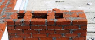
Ventilation shaft arrangement
The structure is usually similar to a cylindrical trunk. It is located strictly vertically and contains three parts:
- one large one – about 300x600 mm;
- two small ones - about 150 mm.
It is the large part that is the trunk, which crosses all floors of the building, from the basement to the attic. The design may be non-standard. Increased dimensions must be taken into account when selecting fans.
Through special windows located in rooms such as the kitchen or bathroom, polluted air enters not very large channels and, rising through them to a height of about three meters, ends up in a common shaft. Thanks to such a device, the spread of used air through the air duct from one room to another, for example, from the kitchen to the bathroom, and then into the rooms, is practically eliminated.
In outbuildings, say, farms or poultry farms, an ideal design for air circulation is considered to be a ventilation shaft near the ridge. They run the entire length of the building's roof in the direction of the ridge.
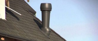
To block access to raindrops, an umbrella is mounted above the outlet of the box. As a rule, in natural air exchange structures a deflector is mounted directly at the mouth. When there are gusts of wind, a vacuum is created here, which contributes to increased traction. But first of all, of course, the deflector prevents the air flow from “tipping over” in the box
When calculating the system, the vacuum created by the wind is not taken into account
Options with artificial air exchange, which help remove aggressive air impurities of the first and second classes, work somewhat differently: polluted air is emitted to a fairly significant height. This type of emission is also called a flare emission.
Height
When placing an exhaust duct on the roof of a building, the minimum permissible distance between it and the air intake of the supply system must be taken into account. According to SNiP:
- horizontally it is equal to ten meters,
- vertically, respectively, six.
The height of the ventilation shaft above the roof is determined according to the following conditions:
- when it is located near the ridge, the mouth, that is, the opening of the hood should be at least half a meter higher than the ridge;
- when located at a distance of one and a half to three meters from the ridge, the hole is flush with the ridge;
- for distances over three meters, the hole is placed along the side of an angle of 10⁰ to the horizon with the apex at the ridge.
In catering premises and food stores, according to SanPiN, the height of the shaft above the roof should not be less than 1 m. Thus, this indicator is a variable value, varying depending on the specific project.
The height of the mouth above the roof for a standard design is usually chosen to be 1 m, in the case of a flare emission - at least 2 m above the highest point of the roof. For emergency situations, the shaft is raised to a height of at least 3 m from the ground.
Material
In residential and public buildings with a system of integrated exhaust ducts, lightweight concrete, brick, and boards lined with galvanized interior are most often used. The inside of the passage shaft is preliminarily covered with felt, which is soaked in a clay solution and plastered on the outside. In industrial buildings, the exhaust structure is mainly made of sheet steel.
Fire safety
When organizing ventilation of a building, all rooms and floors are connected to each other by a network of channels and air ducts, which in itself is dangerous from the point of view of fire safety. Therefore, these elements themselves and the gaskets between them are made of materials that meet SNiP, according to which explosion and fire safety is ensured. In particular, the shaft is separated from the air duct by a partition made of non-flammable and moisture-resistant material.
How to determine the necessary and sufficient height of the ventilation pipe
The absence of a separate method for determining the height of the ventilation system pipe does not mean that such a calculation is not required or is not needed. The easiest way is to make ventilation according to a simplified scheme. If you follow the definitions of SNiP No. 41-01-2003, the height of the ventilation outlet should be:
- On a flat roof - at least 500 mm;
- For a pitched roof, the cut of the ventilation rack should be 500 mm above the ridge line at a distance from the ridge of no more than 1500 mm.
The ventilation outlet can be at the same height as the ridge if the distance does not exceed 3 m, otherwise the cut of the ventilation pipe should not be below a conventional line drawn down to the horizon at an angle of 10°. If there is a stove heating chimney nearby, then the smoke and ventilation pipes must be raised above the chimney cut.
To understand how valid this approximation is, you can perform an approximate calculation of the performance of the ventilation duct. For example, a 16 kW/h heating boiler produces about 140 m 3 of combustion products, the flow of fresh air is provided by a chimney outlet channel with a cross-section of 200-220 cm 2.
In order to provide the required air change rate of 1.5-2 m 3 per hour for residential premises of 60 m 2 with a ceiling height of 2 m, the flow rate is 150 m 3, that is, under certain conditions, the dimensions and installation height of the chimney and ventilation pipe are approximately comparable. The comparison is quite arbitrary, but it clearly shows that the methods are at least comparable.
What does craving depend on?
When the air temperature is low outside and high inside, a certain difference occurs. The larger it is, the more the air from the interior rises upward, that is, the amount of exhaust air increases. When it gets warm outside, the difference decreases and the efficiency of exhaust ventilation decreases.
Impact on ventilation performance
The height of the ventilation pipe above the roof can be calculated, knowing that with an increase in height by 12 m, the pressure of air masses decreases by 101 Pa. The result will be valid for an ideal structure with walls smooth on the inside. When calculating the parameters of the ventilation duct, the structure of the roof, the temperature in the building and outside, and the flow speed at the pipe level are important. Knowing the coefficient C and the pressure drop at the earth's surface and at the installation site, it is possible to calculate the flow of air masses.
It is difficult to carry out calculations on your own, so when arranging a roof with your own hands, you usually rely on reference literature on the design of ventilation systems. They give approximate relationships between air flow and outlet tube extension for different types of roofs. The severity of thrust directly depends on the flow speed.
Installation of ventilation ducts
Choice of length and section:
- pipes for a stainless steel fireplace are selected in such a way that the fireplace pipe has a channel cross-section of at least 16 sq.cm.
- The side of the channel must be at least 10 cm. Pipes are often selected according to the standard 14*14 cm, and the length of such a channel can be 3 m.
- With a larger cross-section (14x27 cm), the length of the channel should be less (2 m).
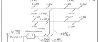
All calculations and nuances of the ventilation system must be carried out in advance. Since it is almost impossible to make changes to the “project” during the work process. Practice has shown that the length of the ventilation ducts of different rooms located on the same level should be almost equal. If the ducts have a large difference in length, this can seriously impair the efficiency of the ventilation. Therefore, it should be remembered that a long exhaust pipe on the roof will have a greater draft force and when the air flow drops, the exhaust force in a shorter channel will significantly decrease. This situation can often arise in the ducts of houses with limited air supply from outside (read: “Chimneys and ventilation ducts, operating rules”).
Features of ventilation installation
The technology for laying air ducts is a sequence of certain operations and depends on the type of ventilation system. However, the installation of a utility network is preceded by its calculation, selection of pipes and marking of their location.
Installation of natural ventilation
The system is laid during the construction of the house or installed in channels specially designed for this purpose. Installation of natural ventilation consists of the following stages:
- securing air ducts;
- installation of grilles and deflectors;
- ensuring air flow through supply valves;
- installation of a hood in the kitchen;
- installation of fans in bathrooms in the grilles of ventilation ducts operating for exhaust.
It should be taken into account that the round ventilation pipe will provide better draft, and the air change will be more efficient.
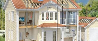
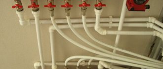
Scheme of natural ventilation of a private house
If, during natural ventilation, the air in the premises is dry and there is a musty smell, then it is necessary to ensure air flow through an additional valve or a slightly open window. The cause of high humidity and mold is insufficient drainage. It is quite difficult to eliminate this defect after construction is completed, and the easiest way is forced ventilation.
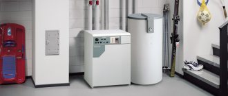
Installation of forced ventilation
This type is indispensable in a country house with a large number of isolated rooms and rooms with high humidity. Installation of forced ventilation is carried out as follows:
- install a supply and exhaust ventilation unit, placing it in an insulated attic;
- connect air ducts to it;
- install an air intake on the outer wall so that the distance to the sewer risers and chimney pipes is at least 10 m;
- if the air ducts were not installed during the construction of the house, then when installing the system they are fixed according to the markings, while the supply ventilation pipe should be located closer to the windows or on the opposite side of the door;
- connect the air ducts to the block using corrugated pipes;
- carry out insulation of ventilation pipes;
- Grilles are installed at the ends of the air ducts, and anemostat sockets are installed at the supply air ducts.
Scheme of forced ventilation of a private house
The optimal choice of ventilation pipes, adherence to their installation technology and regular maintenance of the system will ensure the supply of fresh air to the premises of a private house and will create a comfortable microclimate for its inhabitants.
https://youtube.com/watch?v=SAwNykjmiyw
Related publications:
- Installation of water supply from HDPE pipes
- Laying polyethylene pipes in the ground
- Dimensions of polypropylene pipes
- Laying sewer pipes in a trench
- Laying gas pipelines from polyethylene pipes
- Characteristics of metal-plastic pipes
What is the justification (SNiP or SP) specifically for the height of the ventilation shaft at 500 relative to the level of the flat roof?
Related article: Project of a gable roof rafter system
But what about Sanpin 2.1.2.2645-10 clause 4.9. Exhaust ventilation shafts must protrude above the ridge of the roof or flat roof to a height of at least 1 m.
Sanpin 2.1.2.2645-10 clause 4.9 ventilation tents above the ridge at least 1 m?
Make a lentil-shaped lid over the pipe so that it bulges both up and down. The result will be a diffuser effect and the passing air flow will create a vacuum at the end of the pipe. Ventilation will become forced. Or am I wrong?
Forced ventilation will only work if you install a fan.
We are engaged in major home renovations. GZHI requires the height of ventilation ducts to be raised to two meters. Is this legal? The answer can be sent to /ru
installation of sandwich pipes and brick 89290309018
Advantages of insulation
According to SNiP, insulation makes it possible to create a microclimate in rooms in which people can live and work comfortably. With high-quality insulation:
- heat transfer decreases;
- the formation of condensation, which causes corrosion and mold on the surface of the structure, is prevented;
- the risk of fire is reduced;
- vibration and noise that occur during operation of the air exchange system are weakened;
- heat transfer to the external environment is reduced.
The thickness of the thermal insulation layer depends on such parameters as:
- presence of dew point,
- shape, dimensions of the air vent,
- thermal conductivity of insulation,
- temperature difference between the ventilation system and the room.
The optimal solution is considered to be technical insulation, which has high vapor permeability and low thermal conductivity.
In systems with natural air exchange, as well as with forced air exchange for a certain category of buildings, the presence of insulation is mandatory. For brick ventilation shafts, unlike metal ones, the problem of condensation does not arise, so the issue of thermal insulation loses its relevance.
As for industrial buildings, the forced air exchange shafts here are made of construction steel, which heats up quite quickly. Since a sufficiently large volume of air passes through them, when cooling the structure does not have time to reach the dew point, that is, the problem of water vapor condensation in this case does not arise. The only possibility of condensate formation occurs when the ventilation equipment is stopped, so for such systems, condensate drainage that may form during this period is organized.
How to insulate
Thermal insulation is carried out using two methods: internal insulation and external.
The second is today considered the most economical and efficient. Issues of noise insulation and fire are resolved much easier in this case. For example, noise suppressors are installed directly at the sound source. The likelihood of fire spreading is practically reduced to a minimum. Another valuable advantage of this technology is the ability to periodically carry out measures to prevent the formation of bacteria and microbes, which lead to the delamination of thermal insulation materials, and, therefore, to the loss of their performance characteristics.
To insulate ventilation ducts and cylindrical shafts, gypsum slag or facade mineral wool boards are most often used. The process of installing thermal insulation, say, for mini-slabs, is carried out in the following sequence:
- prepare the surface, in particular, remove weak areas of the base, prime the surface;
- Minslabs are laid on glue, and blotches and edging are also made from it;
- after waiting for final drying, install the façade dowels;
- lay a reinforcing layer containing a mesh of fiberglass and glue;
- after complete drying, the surface is primed and covered with decorative plaster.
2019stylekrov.ru
Types of ventilation ducts
There are three types of ventilation channels:
- Channels built into the walls, which are installed in the load-bearing walls during the construction of a building.
- Suspended or overhead air ducts are installed in buildings during renovation or reconstruction.
- Attached or external ventilation ducts that are mounted outside.
Built-in channels are laid out of bricks without voids (heat-resistant or fire-resistant) or concrete blocks specially made for these purposes. Although the ventilation system does not have the same thermal load as in the chimney, sand-lime brick cannot be used, since it collapses quickly even with small temperature changes.
Prefabricated reinforced concrete segments are more convenient and practical to use. Their ventilation duct has smoother walls, which means greater efficiency.
In terms of aerodynamic characteristics, the first can be called an air duct made of asbestos pipe. It has perfectly smooth walls and a round cross-section, which prevents the formation of air vortices. Asbestos pipes are “inserted” into the internal brick walls during the construction of the house, lining them around them.
Suspended or overhead ventilation ducts or air ducts are built from galvanized steel, plasterboard or plastic. Vertical sections are mounted close to the walls, horizontal sections - under the ceiling. As a rule, they are used for forced ventilation systems. In industrial premises, ventilation ducts are often installed from round galvanized pipes.
Note! Steel without a protective coating is not used for ventilation ducts, since air flows contain acid oxides and water vapor, which quickly destroy iron.
External ventilation ducts are built from brick, concrete, galvanized steel with mandatory insulation of the walls to prevent the formation of condensation inside the system. They are built from brick, reinforced concrete or steel.
We recommend that you read: Installing a proper ventilation system in a private home
Special requirements for materials for air ducts are imposed where the removed air flows contain chemically aggressive substances or have a high temperature. Here they use stainless steel or steel with a special polymer coating. In some cases, ventilation ducts are built from aluminum.
Chemical plants use ventilation systems made of ceramics. For rooms where the air heats up above 100 degrees, ventilation is mounted from steel with a thickness of at least 1 mm.