Heat carriers (cooling fluids for heat exchange systems) are working media that, during the heat exchange process, either remove excess heat or are used for heating in various production technologies, as well as for heating residential, office and industrial buildings and structures.
To increase the efficiency of the heat exchange process in heating systems, different types of coolant fluids are used as working media. Initially, plain water or, in some cases, steam was used. Subsequently, such technologies lost their development as they became ineffective and expensive. Heat exchange equipment rusts quite quickly, the water has to be constantly changed, and cooling occurs too quickly.
In order to increase the operating efficiency of heat exchange equipment and improve the operation of heat exchange systems, new types of all-season low-freezing coolant compositions with long service life in heating systems have been developed.
At the present stage of development of industrial production, the most widely used working media for heat exchange systems are aqueous solutions of glycols (ethylene glycol, propylene glycol) or glycerin containing additive packages that improve their performance characteristics. Today these are the most efficient working media used in heat transfer processes.
There are many types of coolants, the physical and chemical characteristics of which differ slightly from each other, which makes it possible to choose the most suitable one, taking into account the conditions of its further use.
From this many types of popular coolants, the following most common groups can be roughly distinguished:
- water (water-salt solutions);
- ethylene glycol, propylene glycol (water-glycol solutions);
- mixtures.
Each of the coolants of these groups has its own characteristic advantages and disadvantages.
Characteristics of water as a heat conductor
Many heating systems are filled with water as a working medium - the most accessible and versatile coolant. It is freely available, and its reserves in nature are regularly renewed. Up to 70% of heating systems are filled with natural liquid.
The popularity of water is due not only to its availability, but also to environmental safety. Also among its positive features are high density and specific heat capacity. An important performance characteristic is low chemical activity, good heat transfer coefficient, minimal viscosity. Water meets all these requirements. If necessary, its heating temperature can be adjusted.
Among the characteristics of natural liquid, there are also disadvantages. These include:
- low upper heating limit (temperature maximum in the heating system up to 150 °C);
- freezes at 0 °C, turning into a crystalline form with a significant increase in volume, which leads to the destruction of equipment and pipelines of heating systems;
- the possibility of corrosion processes with the formation of metal oxides (rust) and destruction of equipment surfaces;
- scale formation on pipeline surfaces when heated to 80 °C.
If water freezes in the pipes in winter, the entire heating system may become unusable. Often rust and deposits appear on metal pipes and fittings. To minimize the risk of their occurrence, distilled water is used or special additives and alkalis are added to process water.
Heating devices where water serves as a coolant require regular maintenance - flushing heat exchangers and pipelines, periodic boiler repairs, and adjustment of resistivity during the heating season.
Water as a coolant
Heating systems mainly use water, which is the safest, most inexpensive and environmentally friendly coolant. The reason for this is the highest heat capacity among liquids and no less high density. Thus, one kilogram of water heated to 90ºС, cooling to a temperature of 70ºС, is capable of releasing 20 kcal of heat.
If a leak occurs, the volume of coolant in the heating system can be easily replenished by pouring the missing amount into it. Water has no competitors in terms of price - consumers cannot find a cheaper liquid. At the same time, you should know that experts do not recommend using ordinary tap water in heating systems, since it contains a lot of salts and oxygen, which will certainly lead to the appearance of scale and corrosion processes.
The process of water softening helps to eliminate the problem with the functioning of the equipment.
You can use one of two methods:
- The first option is thermal, which is based on conventional boiling
. Water is placed in a metal container and heated. When boiling, salts are deposited at the bottom of the tank. Carbon dioxide is also removed, but persistent calcium and magnesium compounds are still present in the water. - The second option is chemical and involves the use of reagents
. The use of soda ash, sodium orthophosphate and slaked lime makes the salts present in the water insoluble, after which they precipitate. Residues of these substances are removed by filtration.
It is considered ideal to fill the heating system with a coolant, which is distilled water. The only disadvantage of filling the heating system with water is the need to purchase it, while ordinary water is taken from the tap, however, you also have to pay for it, but much less than for distilled water. You can use rainfall, which compares favorably with well, artesian or tap water.
For such a coolant, its temperature regime is of great importance. If the temperature in the house drops below 0 degrees, frozen liquid will pose a serious threat to the integrity of the heating structure.
Technical properties of glycol-based coolants
Since 01/01/2017, GOST 33341-2015 “All-season low-freezing compositions and cooling liquids for heat exchange systems” has been put into effect for coolants, which use the specific properties of their water as base components - glycols (ethylene glycol, diethylene glycol, triethylene glycol, propylene glycol). solutions do not acquire a solid phase at negative ambient temperatures.
Dozens of types of coolants have been developed based on glycols for use in various heat exchange systems. These are not only liquids for the municipal sector, but also compositions for industrial heat exchange plants. Such compositions provide good heat transfer and allow maintaining high efficiency of the heat transfer process.
The compositions can be used while maintaining optimal conditions for up to 5-7 years without their regeneration. After the warranty period has expired and the quality has been checked, you can restore or replace the composition and continue operation.
Criteria for choosing a coolant for a heating system
When choosing a particular coolant for a heating system, the following factors should be taken into account:
• not all types of coolants are suitable for a particular boiler, so you should first read the operating instructions for the equipment;
• the material from which the pipes and main components of the system are made plays an important role; liquid passes through them;
• it is better to choose a product that can be adjusted in temperature conditions;
• the composition should not contain toxic substances;
• some types of coolant are produced that can only be used in industrial buildings; using it in a residential building is strictly prohibited;
• if the pipeline is made of galvanized metal, you cannot fill in antifreeze, as the chemical composition of the liquid will change;
• high heat capacity, thermal conductivity with low viscosity will ensure effective heat transfer;
• affordable cost;
• long service life.
In terms of physical properties and chemical composition, the most suitable liquids are water and antifreeze.
Heat transfer fluids based on ethylene glycol
For some heating units to operate, it is necessary to use a coolant that freezes only at very low temperatures. Low-freezing coolant (or antifreeze) based on ethylene glycol is one of them.
The low temperature at which crystallization of these types of coolants begins depends on the ratio of the base component - ethylene glycol and distilled water in solution. To improve the performance characteristics of these coolants, a package of functional additives is added to their composition, which protect the metal surfaces of equipment from the corrosive effects of ethylene glycol.
Antifreeze is suitable for use in automotive cooling systems of internal combustion engines and in systems that are used for heating buildings, structures and as a coolant in various industries. It belongs to the category of mid-price coolants.
The temperature at which this type of coolant begins to crystallize can reach minus 70 °C and does not form deposits on the heat pipes.
Among the key characteristics of such a coolant are the following:
- low-freezing properties (freezing depends on the concentration of ethylene glycol in the solution);
- practicality and safety of use (during cooling and crystallization it acquires an amorphous structure - it does not expand significantly, and therefore is not capable of damaging the heating system equipment);
- contains a package of additives (protecting against corrosion, scale, foaming and stabilizing, antioxidant);
- does not change its original basic special properties throughout the entire service life;
- has a high initial boiling point in a closed system;
- does not have an aggressive effect on various materials (metal, plastic, rubber, textiles) during the warranty period, since the composition contains the necessary additives in sufficient quantities.
The main disadvantage of such a coolant is its toxicity. They are moderately toxic in terms of their effects on the human body (hazard class 3) and dangerous in terms of environmental parameters. For this reason, it is not used in open heating systems. When using it, it is important to prevent it from coming into contact with any objects. Otherwise, it would be advisable to replace them.
Features of choosing a coolant
In order for the heating of the room to be effective and the system to function correctly, you need to know how to calculate the volume of coolant in the home heating system.
The approximate value of this indicator can be determined from the ratio: 1 kW of power equals 15 liters of liquid. But it is advisable to know the exact data. For these purposes, special calculation tables have been developed. Based on them, the volume of coolant in the heating system for the aluminum radiator section is 0.45 liters. And the cast iron battery section holds about 1 liter of liquid.
It is also important to determine the coolant flow rate in the building’s heating system. This indicator is calculated by dividing the estimated heat demand by the heat output of 1 kg of circulating fluid. Flow is usually measured in kg/h.
Thus, different types of circulating fluid are commercially available today. Which heating fluid to buy depends on the parameters of the heating system, operating conditions, and the size of the budget.
Heat transfer fluids based on propylene glycol
Propylene glycol compositions and cooling liquids, the mass distribution of which is limited by the expensive basic working component - propylene glycol, have become widespread with the introduction of coolants in food production technologies, as well as in the pharmaceutical industry. Their main advantage over ethylene glycol is that they are safer for humans and the environment.
The following main characteristics can be distinguished:
- does not cause poisoning, aqueous solutions of propylene glycol are explosion- and fire-proof and, accordingly, their vapors practically do not contain the basic active component;
- suitable for heating residential buildings and public buildings;
- has low chemical aggressiveness;
- suitable for materials, and primarily equipment made of metals, on which corrosion occurs upon contact with water;
- prevents water hammer and has a good lubricating effect.
The disadvantages characterizing propylene glycol coolants include:
- the need for replacement every 5 years, coolants with a standard set of additive packages. To increase the period of reliable operation, it is necessary to use a package with carboxylate additives to obtain the “Carbo-ECO-TEN” trademarks;
- high cost;
- at subzero temperatures, coolants have a high viscosity and at the same time are characterized by increased fluidity, so they can easily penetrate through loose connecting parts of the heating system (even where water does not seep through).
Propylene glycol
The desire to find a less toxic antifreeze with sufficient thermophysical characteristics for use as a coolant has led to the filling of heating systems with propylene glycol. According to statistics, only 5% of heating systems use propylene glycol as a coolant.
A significant advantage of this substance is its environmental safety and the absence of negative effects on human health. If propylene glycol leaks, you can simply wipe it off with a rag without taking special precautions. The vapors of the substance are also completely safe for humans. Antifreezes based on it are characterized by frost resistance; they freeze at temperatures of -60°C - -70°C.
Another important advantage of the substance is its low chemical aggressiveness. When using propylene glycol, you can use materials that are contraindicated for contact with water due to the high likelihood of corrosion. Even if water is completely removed from the mixture, frost resistance will remain at -60°C. While ethylene glycol in a similar situation freezes at -13°C. Due to its lubricating effect, the use of propylene glycol helps prevent water hammer.
The thermophysical parameters of propylene glycol are only 20% inferior to ethylene glycol. However, the cost of this coolant is significantly higher than the cost of ethylene glycol.
Coolants in the form of mixtures
Another group of coolants used in heat exchange systems includes compositions and cooling liquids based on aqueous solutions of the basic working component - glycerin. These are modern and promising developments with high efficiency and little potential harm to the environment.
According to customer requirements, coolants for use in heating installations can be produced on the functional basis of mixing two bases - propylene glycol and ethylene glycol. Such mixtures combine the characteristics of two active base components. Due to the increased viscosity of propylene glycol at low temperatures, this disadvantage is offset by the addition of ethylene glycol to the mixture. However, this deteriorates the environmental parameters and safety of coolants.
In fact, even water and coolants based on aqueous solutions of glycols can also be classified as mixed coolants.
Parameter control methods
Three methods are used to regulate the heat load:
- Quantitative.
- Qualitative.
- Quantitative and qualitative.
With the quantitative method, the heat load is regulated by changing the amount of coolant supplied. With the help of heating network pumps, the pressure in the pipelines increases, and heat output increases with increasing coolant flow rate.
The qualitative method consists of increasing the parameters of the coolant at the outlet of the boilers while maintaining the flow rate. This method is most often used in practice.
With the quantitative-qualitative method, the parameters and flow rate of the coolant are changed.
Factors affecting room heating during the heating season:
- water parameters in the supply pipeline;
- outside air temperature;
- wind speed, leading to an increase in drafts and heat transfer from window frames and doors;
- thermal insulation of walls.
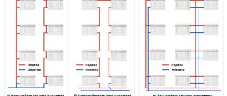
Heat supply systems are divided depending on the design into single-pipe and two-pipe. For each design, its own thermal schedule in the supply pipeline is approved. For a one-pipe heating system, the maximum temperature in the supply line is 105 degrees, in a two-pipe heating system - 95 degrees. The difference in supply and return temperatures in the first case is regulated in the range of 105-70, for a two-pipe system - in the range of 95-70 degrees.
The main characteristics that you need to focus on when choosing a coolant
There are a number of requirements for work environments. Each of them is a specific characteristic of coolants for heat exchange systems, including heating processes.
- Good heat storage capacity, allowing to reduce energy costs for movement.
- Transportability. It is important to have a stable state of aggregation and the ability to transfer heat (cold) over the required distances.
- Low level of toxicity or its minimal impact on the health of personnel.
- Environmental Safety. It is necessary that possible unintended leaks and emissions do not have a negative impact on the environment.
- Chemical inertness in relation to materials of heat exchange systems and technological equipment of various industries (metals, alloys, sealing products, rubber, etc.).
- Optimal operating temperature range, which ensures stability of heat transfer and stable control of the modes of various production processes and reduces operating costs.
- Explosion and fire safety. It is important that the heated coolant does not ignite when in contact with air.
Some physical characteristics are no less important: a high thermal conductivity coefficient, the value of the coefficient characterizing surface tension and the optimal viscosity value over a wide temperature range.
specializes in the production and sale of industrial coolants of a wide range of different brands.
Coolants and their parameters
8.1 In centralized heat supply systems for heating, ventilation and hot water supply of residential, public and industrial buildings, water should, as a rule, be used as a coolant.
The possibility of using water as a coolant for technological processes should also be checked.
The use of steam as a single coolant for enterprises for technological processes and hot water supply is allowed during a feasibility study.
8.2 The maximum design temperature of network water at the outlet of the heat source, in heating networks and heat-using installations of consumers is established on the basis of technical and economic calculations.
If there is a hot water supply load in closed heat supply systems, the minimum temperature of network water at the outlet of the heat source and in heating networks must ensure the ability to heat the water supplied to the hot water supply to a standardized level in accordance with the requirements of TKP 45-4.01-52.
8.3The temperature of network water returned to thermal power plants with combined heat and electricity production is determined by technical and economic calculations.
8.4 When calculating graphs of network water temperatures, the beginning and end of the heating period are assumed to be at an average daily outside air temperature of 8 °C, while the average internal air temperature in heated buildings is assumed to be 18 °C.
8.5In the absence of automatic individual devices for regulating indoor temperature in heat-using installations (heating and ventilation systems), heat supply regulation should be used in heating networks:
- central quality for the heating load or for the combined load of heating, ventilation and hot water supply - by changing the coolant temperature at the heat source depending on the outside air temperature;
- central qualitative and quantitative control of the combined load of heating, ventilation and hot water supply - by regulating both the temperature and the flow of network water at the heat source.
Central qualitative and quantitative regulation at the heat source can be supplemented by group quantitative regulation at heating points, starting from the break point of the temperature graph, taking into account the connection diagrams of heating, ventilation units and hot water supply, pressure fluctuations in the heating system, the presence and location of storage tanks, heat storage capacity of buildings and structures.
8.6 In heat supply systems, if the heat consumer has automatic individual devices for regulating indoor air temperature in the heating and ventilation systems with the amount of network water flowing through heat-using installations, central qualitative and quantitative regulation should be used, supplemented by group quantitative regulation at heating points in order to reduce hydraulic fluctuations and thermal regimes in specific quarterly (microdistrict) systems within the limits ensuring the quality and sustainability of heat supply.
8.7 When centrally regulating the supply of heat for heating water in hot water supply systems to consumers, the water temperature in the supply pipeline should be taken for heat supply systems, °C:
— closed — at least 70;
- open - the same 60.
With central qualitative and quantitative regulation for the combined load of heating, ventilation and hot water supply, the break point of the water temperature graph in the supply and return pipelines should be taken at the outside air temperature corresponding to the break point of the control graph for the heating load.
8.8 The creation of new heat supply systems must be organized primarily using quantitative regulation of heat supply.
For separate water heating networks from one heat source to enterprises and residential areas, it is allowed to provide different coolant temperature schedules.
8.9In public and industrial buildings for which it is possible to reduce the air temperature at night and during non-working hours, regulation of the temperature or coolant flow in heating points should be provided.
8.10In residential and public buildings, if the heating devices do not have thermostatic valves, automatic control should be provided according to the temperature schedule to maintain the average internal air temperature in the building.
9 Hydraulic modes and calculations
9.1 Hydraulic modes of water heating networks (piezometric graphs) should be developed for heating and non-heating periods, as well as for emergency modes.
For open heat supply systems during the heating season, three additional modes are being developed: with maximum water withdrawal from the supply and return pipelines and in the absence of water withdrawal (night mode).
9.2 When designing new and reconstructing existing central heating systems, as well as when developing measures to improve the reliability of all parts of the system, the calculation of hydraulic modes is mandatory.
9.3 The estimated flow of network water to determine the diameters of pipelines in water heating networks should be determined separately for heating, ventilation and hot water supply using formulas (1) - (8), followed by summing up these water flows using formulas (9) - (11).
9.4 Estimated water consumption, kg/h, should be determined using the formulas:
a) for heating
(1)
b) for ventilation
(2)
c) for hot water supply in open heating systems:
- average
(3)
— maximum
(4)
d) for hot water supply in closed heating systems:
- medium, with parallel connection of water heaters,
(5)
— maximum, with parallel connection of water heaters,
(6)
- average, with two-stage water heater connection schemes,
(7)
— maximum, with two-stage water heater connection schemes,
(8)
where t1 is the water temperature in the supply pipeline of the heating network at the design outdoor temperature t
0, °C;
t2 — water temperature in the return pipeline of the heating network, °C;
— water temperature in the supply pipeline of the heating network at the break point of the water temperature graph, °C;
— water temperature in the return pipeline of the heating network after the building heating system, °C;
— water temperature after a parallel-connected hot water supply water heater at the break point of the water temperature graph; recommended to take = 30 °C;
G
omax — maximum water consumption for heating, kg/h;
Gv
max — maximum water flow for ventilation, kg/h;
Ghm
,
Gh
max - average and maximum water consumption for hot water supply, kg/h;
t
¢ — water temperature after the first heating stage with two-stage water heater connection schemes, °C;
tc
— temperature of cold (tap) water during the heating period (in the absence of data, taken equal to 5 °C);
th
— temperature of water entering the hot water supply system for consumers, °C;
With
— specific heat capacity of water, assumed in calculations to be 4.187 kJ/(kg×°C).
9.5 The total estimated consumption of network water, kg/h, in two-pipe heating networks in open and closed heat supply systems with high-quality regulation of heat supply should be determined by the formula
Gd
=
G
omax+
Gv
max+
k
3
Ghm
.(9)
Factor k
3, which takes into account the share of average water consumption for hot water supply when regulating according to the heating load, should be taken according to Table 2. When regulating according to the combined load of heating and hot water supply, the coefficient
k
3 is taken equal to zero.
table 2
| Heating system | The value of the coefficient k 3 |
| Open with heat flow, MW: 100 or more less than 100 Closed with heat flow, MW: 100 or more less than 100 | 0,6 0,8 1,0 1,2 |
| Note - For closed heat supply systems when regulated by heating load and heat flow of less than 100 MW, in the presence of storage tanks at consumers, the coefficient k 3 should be taken equal to unity. |
For consumers in the absence of storage tanks, as well as with a heat flow of 10 MW or less, the total calculation of water consumption should be determined using the formula
(10)
9.6 The estimated water consumption, kg/h, in two-pipe water heating networks during the non-heating period should be determined by the formula
(11)
where b is a coefficient taking into account the change in the average water consumption for hot water supply in the unheated period in relation to the heating period, taken in the absence of data for the housing and communal sector as 0.8 (for resort and southern cities - 1.5), for enterprises - 1.0.
In this case, the maximum water consumption for hot water supply, kg/h, is determined for open heat supply systems using formula (4) at the cold water temperature during the non-heating period, and for closed systems with all connection schemes for hot water supply water heaters - using formula (6).
The water flow in the return pipeline of two-pipe water heating networks of open heat supply systems is taken in the amount of 10% of the calculated water flow, determined by formula (11).
9.7 The estimated water flow to determine the diameters of supply and circulation pipelines and hydraulic calculations of hot water supply networks should be determined in accordance with TKP 45-4.01-52.
9.8 Steam consumption in steam heating networks supplying enterprises with different daily operating modes should be determined taking into account the discrepancy between the maximum hourly steam consumption of individual enterprises.
For saturated steam steam pipelines, the total flow rate must take into account the additional amount of steam condensing due to heat loss in the pipelines.
9.9 Equivalent roughness k
e of the internal surface of steel pipes should be taken, m:
0.0002 - for steam heating networks made of steel pipes;
0.0005 — “water heating networks made of steel pipes;
0.001 - “hot water supply networks made of steel pipes;
5×10⁻⁶ - “pipelines made of polymer materials.
9.10 The smallest nominal diameter of pipelines should be at least 32 mm in heating networks, and at least 25 mm for hot water circulation pipelines.
9.11 The static pressure in heat supply systems with water coolant must be determined for a network water temperature of 100 °C. In static modes, unacceptable increases in pressure in pipelines and equipment should be excluded.
9.12 The water pressure in the supply pipelines of water heating networks during operation of network pumps must be taken based on the conditions of non-boiling water at its maximum temperature at any point in the supply pipeline, in the equipment of the heat source and in the heat-using installations of consumers directly connected to the heating networks.
9.13 The water pressure in the return pipelines of water heating networks during operation of network pumps must be excessive (at least 0.05 MPa) and 0.1 MPa below the permissible pressure in heat-using consumer installations.
9.14 The water pressure in the return pipelines of water heating networks of open heating systems during the non-heating period, as well as in the supply and circulation pipelines of hot water supply networks, should be taken at least 0.05 MPa greater than the static pressure of hot water supply systems to consumers.
9.15 The pressure and temperature of water in the suction network pipes, make-up, booster and mixing pumps should not be lower than the cavitation pressure and should not exceed those permitted by the strength conditions of the pump designs.
9.16 The pressure of network pumps should be determined for the heating and non-heating periods and taken equal to the sum of pressure losses in installations at the heat source, in the supply and return pipelines from the heat source to the most distant consumer and in heat-using consumer installations (including losses in heating points and pumping stations) with total estimated water consumption.
The pressure of booster pumps on the supply and return pipelines should be determined using piezometric graphs at maximum water flow rates in the pipelines, taking into account hydraulic losses in equipment and pipelines. Hydraulic calculations of pipelines should be carried out as given in Appendices B and C.
9.17 The pressure of make-up pumps should be determined from the conditions for maintaining static pressure in water heating networks and checked for the operating conditions of network pumps during the heating and non-heating periods.
It is allowed to provide for the installation of separate groups of make-up pumps with different pressures for heating, non-heating periods and for static mode.
9.18 The supply (performance) of working make-up pumps at the heat source in closed heat supply systems should be taken equal to the water flow to compensate for losses of network water from the heating network and at heat-using consumer installations, and in open systems - equal to the sum of the maximum water flow for hot water supply and water flow for compensation for losses.
9.19 The pressure of mixing pumps should be determined by the greatest pressure difference between the supply and return pipelines.
9.20 The number of pumps should be taken:
— network — at least two, one of which is a backup; with five working network pumps in one group, a backup pump may not be installed;
- booster and mixing pumps (in heating networks) - at least three, one of which is a backup pump, and a backup pump is provided regardless of the number of working pumps;
- make-up - in closed heat supply systems at least two, one of which is a backup, in open systems - at least three, one of which is also a backup;
— in the nodes of dividing the water heating network into zones (in the cutting nodes), it is allowed to install one make-up pump without a reserve in closed heat supply systems, and in open systems - one working and one reserve.
The number of pumps is determined taking into account their joint work on the heating network.
9.21 When determining the pressure of network pumps, the pressure drop at the input of two-pipe water heating networks into buildings (with elevator connection of consumer heating systems) should be taken equal to the sum of the calculated pressure losses at the input and in the heating system with a coefficient of 1.5, but not less than 0.15 MPa. It is recommended to throttle the excess pressure at the entrance to the buildings at the heating points of the buildings.
9.22 When designing a central heating system with a heat consumption of more than 100 MW, it is necessary to determine the need for an integrated protection system that prevents the occurrence of water hammer and unacceptable pressures in the equipment of water heating installations of heat sources, in heating networks, and heat-using installations of consumers.