4.1. Heat output scale for hot water boilers
The purpose of hot water boilers is to obtain hot water of specified parameters for heat supply to heating systems of household and technological consumers.
The industry produces a wide range of water heating boilers that are standardized in design. The characteristics of their operation are heat output (power), temperature and water pressure, and the type of metal from which hot water boilers are made is also important. Cast iron boilers are available for heating capacity1 to 1.5 Gcal/h, pressure 0.7 MPa and hot water temperature up to 115 °C. Steel boilers are manufactured in accordance with the heat output scale of 4; 6.5; 10; 20, 30; 50; 100; 180 Gcal/h (4.7; 7.5; 11.7; 23.4; 35; 58.5; 117 and 21.0 MW). Hot water boilers with a heating capacity of up to 30 Gcal/h usually provide operation only in the main mode with water heating up to 150 °C with a water pressure at the boiler inlet of 1.6 MPa. For boilers with a heating capacity above 30 Gcal/h, it is possible to operate in both main and peak modes with water heating up to 200 °C with a maximum pressure at the boiler inlet of 2.5 MPa.
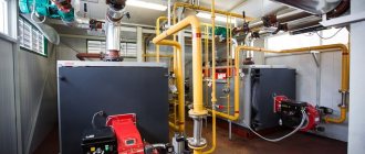
Why is it beneficial to use a hot water boiler room?
The task of hot water boiler houses is to provide heat and hot water to various construction and industrial facilities, educational and medical institutions, agricultural and housing and communal services facilities.
At the moment, such a boiler house represents a cost-effective solution; moreover, it is one of the most advanced modern heat-generating devices from an engineering point of view.
Current hot water boiler houses of large, medium, and low power consume fuel and electricity quite efficiently and more economically. The costs of building a boiler house these days are approximately equal to the cost of connecting to a central heating supply.
But the main thing is hot water boiler houses located close to consumers, due to which they can significantly reduce the length of heating networks, and this can significantly reduce the length of heat losses, which has a beneficial effect on the efficiency of the entire system in general.
The use of hot water boiler systems made from modern equipment is economically beneficial for the consumer for the following reasons:
- The efficiency of the boiler room is 92-93%, thanks to the automation of work processes, the use of hot water boilers, pumps, burners, shut-off valves and other modern equipment, which has a high reliability coefficient;
- Quite a lot of money is saved due to a reduction in the cost of paying for energy resources, a reduction in heat losses during transportation to the consumer, and due to the fact that CVRs are installed as close to the consumer as possible;
- the design of the boiler house itself can also be reduced by using standard components and blocks that have already been tested at other facilities and have proven their reliability and efficiency;
- fairly low costs for transporting boiler house blocks to the installation site;
- low costs during installation, all blocks and modules are assembled from quickly assembled components and assemblies;
- the work process thanks to control automation makes it possible to significantly reduce the cost of operating a hot water boiler house;
- As a rule, a new hot water boiler house usually fully pays for itself within 2-3 years.
At the same time, water heating boilers that run on electricity are the most popular, since such units have a less complex design, unlike, for example, gas boilers, and do not require constant maintenance. In addition, they are easy to use and non-explosive.
4.2. Cast iron sectional hot water boilers
Cast iron sectional water heating boilers have a low heating output and are mainly used in water heating systems of individual residential and public buildings. Boilers of this type are designed to heat water to a temperature of 115 °C at a pressure of 0.7 MPa. In some cases, cast iron boilers are used to produce water steam; for this purpose they are equipped with steam collectors.
Of the large number of different designs of cast iron sectional boilers for industrial production, the most widely used boilers are the types “Universal”, “Tula”, “Energia”, “Minsk”, “Strelya”, “Strebelya”, “NRch”, KCh and a number of others.
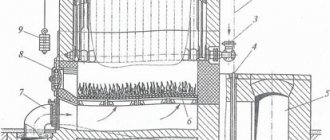
Rice. 4.1. Cast iron sectional hot water boiler "Energia-3" :
1 - boiler section; 2 - steel rope; 3, 10 - pipes for water inlet and outlet; 4 - gate; 5 - chimney; 6 — grate; 7 - air duct; 8 - door; 9 - counterweight
The production of most of these types of boilers ceased about 30 years ago, but they will still be in operation for quite a long time. In this regard, as an example, let us consider the design of a cast-iron sectional water heating boiler “Energia-3”. The boiler is assembled from separate sections (Fig. 4.1), connected to each other using liners - nipples, which are inserted into special holes and tightened with coupling bolts. This design allows you to create the required heating surface of the boiler, as well as replace individual sections in case of damage.
Water enters the boiler through the lower pipe, rises up through the internal channels of the section, heats up and leaves the boiler through the upper pipe. Fuel is supplied to the firebox through the door opening. The air required for combustion enters under the grate through air duct 7. Combustion products formed during fuel combustion ( GHGs) move upward, then the direction of GHG flow changes by 180°, i.e. the G1G flow moves down the brick channels and is then directed through a common collection chimney into the chimney.
When moving, the steam generators are cooled, their heat is transferred to the water located inside the sections. In this way, the water is heated 66 to the required temperature. The draft in the boiler is regulated by a gate connected by a steel rope through a block with a counterweight. The rated power of the Energia-3 water heating boilers is 0.35... 0.69 MW, efficiency 73%.
Electric hot water boilers - features and reasons for popularity
Such natures are very popular in Russia. They are produced by many manufacturers - both Russian and foreign. These boilers make it possible to provide housing not only with heat, but also with heated water, regardless of whether there is a centralized hot water supply in your area.
Electric boilers have a simpler design than, for example, gas boilers and do not require regular maintenance. Moreover, they are easy to operate and cannot explode. What can we say about such an important parameter as environmental safety?
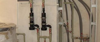
Design features of electric hot water boilers
Such devices consist of the following elements:
- heat exchanger (it is a container in which an electric heating element is built);
- automation (necessary to maintain the required temperature in the room, but without direct human participation);
- closet.
Typically, not only ordinary water, but also non-freezing liquid can act as a coolant (this option is more preferable). Such boilers can also be divided according to the type of heating element used.
- Models with tubular heating elements. Such elements are filled with a special conductor that heats up when in contact with electricity. Capable of permanently heating running liquid, but subject to connection to an electrical network. Tubular heating elements are used in cases of combined heating. Who doesn’t know, during the day such systems operate from a heating device using liquid/solid energy or gas, while at night, when the cost of electricity decreases, they keep the house warm using it.
- Models with electrodes. Electrode-type units heat the liquid through an ion flow that forms between the electrodes (this is written in the description). The main advantage is the absence of heating elements, but due to the fact that the most important component of the circuit is the coolant, it must be properly prepared. Salt must be added to the liquid in a certain amount to obtain the desired concentration.
Note! As we have already found out, the main advantage of any electric boiler is its affordable price, ease of installation and operation, small dimensions and weight, and the absence of the need to arrange a separate room.
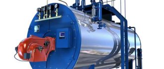
4.3. TVG series hot water boilers
Cogeneration water heating boilers of the TVG series are produced with a heating capacity of 4 and 8 Gcal/h (4.7 and 9.4 MW). These sectional welded boilers are designed to operate on gas with water heating not exceeding 150 °C.
Rice. 4.2. Water heating boiler TVG-8 : a - water circulation diagram; o - boiler design; 1, 2 - lower and upper collectors of the convective surface, respectively; 3, 5 — ceiling-front pipes; 4, 6 - lower and upper collectors of the ceiling screen; 7 — left side screen; 8, 14 — two-light screens; 9 — right side screen; 10 - water outlet to the heating network; 11 — convective heating surface; 12 — radiation surface of the furnace; 13 — air channel; 15 — burners; 16 - sub-pod channels
In the TVG-8 water heating boiler, the radiation surface of the furnace 72 (Fig. 4.2) and the convective heating surface 77 consist of separate sections made of pipes with a diameter of 51 * 2.5 mm. In this case, in sections of the convective surface the pipes are located horizontally, and in sections of the radiation surface - vertically. The radiation surface consists of a front-ceiling screen and five sections of screens, three of which are double irradiated (two-light screens 8 and
The boiler is equipped with hearth burners 75, which are located between the sections of the radiation surface. Air from the fan enters the air channel from which it is supplied to the sub-channels connected to the burners. The fuel combustion products move along the pipes of the radiation surface, pass through the window in the rear part of the furnace and enter the lower shaft, washing the convective surface with a transverse flow. At the same time, water for heating enters the two lower collectors 7 of the convective surface and is collected in the upper collectors of the convective surface. Next, through several ceiling-front pipes, water is directed to the lower collector of the ceiling screen, from where it flows through the ceiling-front pipes to the upper collector of this (ceiling) screen. After this, the water sequentially passes through the pipes of the screens: the left side 7, three two-light and the right side. The heated water through the collector of the right side screen enters the outlet into the heating network.
Water heating boilers of the TV G series have an efficiency of 91.5%.
4.4. Steel hot water boilers of the KV-TSi series KV-TSV
Hot water boilers of the KV-TS series with a layered method of burning solid fuel are produced with a heating capacity of 4; 6.5; 10; 20; thirty; 50 Gcal/h (4.7; 7.5; 11.7; 23.4; 35 and 58.5 MW). Boilers of this series are intended for installation at thermal power plants, in industrial heating and heating boiler houses. Water heating boilers of the KV-TSV series differ from boilers of the KV-TS series only in the presence of an air heater.
All hot water boilers of both these series have combustion screens made of pipes with a diameter of 60 x 3 mm. Convective bags in them are made from pipes with a diameter of 28 x 3 mm. The boilers are equipped with chain return grates with pneumomechanical fuel throwers.
Hot water boilers KV-TS-4 and -6.5 have a convective shaft (Fig. 4.3) with a heating surface and a combustion chamber
Rice. 4.3. Water heating boilers KV-TS-4 and -6.5 :
1 - window for the exit of combustion products from the combustion chamber; 2 - convective shaft with heating surface; 3 - nozzle for returning fuel carryover to the chain grid; 4 - slag bunker; 5 - reverse chain grille; 6 — pneumomechanical fuel thrower; 7 — fuel bunker; 8 - combustion chamber
camera; GHG - combustion products
Fuel (coal) from the hopper 7 is supplied to the return chain grid 5 by means of a pneumo-mechanical spreader. Air for fuel combustion is supplied by a fan into the ducts, through which it is sectioned and supplied under the chain grate. The fuel combustion products from the combustion chamber enter the convective shaft through the upper openings in the rear wall of the combustion chamber (windows). The heat of the GHG is perceived by convective heating surfaces in convective shaft 2, and cooled GHGs are removed from the boiler through a gas duct located in the lower part of the convective shaft. With the GHG flow Fuel is partially carried away from the combustion chamber; to catch it, a special fan is installed in the convection shaft bunker, which returns the carried away fuel through the nozzles to the combustion chamber onto the chain grate.
equipped with chain return grids 7 of different lengths and two pneumomechanical fuel throwers. In the rear part of the combustion chamber there is an intermediate shielded wall 6, forming an afterburning chamber. The screens of the intermediate wall are made of two rows. The side walls of the combustion chamber, as well as the convection shaft, have lightweight lining. The front wall of the combustion chamber is not shielded and has heavy lining.
The front and rear walls of the convection shaft are shielded. The front wall of the convective shaft, which is also the rear wall of the combustion chamber, is made in the form of an all-welded screen, turning into a four-row scallop at the bottom. The side walls of the convective shaft are closed with vertical screens made of pipes with a diameter of 83 3.5 mm.
Combustion products enter the convective shaft from below and pass through the festoon. The shaft contains packages of convective heating surfaces made in the form of horizontal screens. Collected fines and unburned fuel particles are collected in ash bins under the convective shaft and, through the entrainment return system, are thrown into the combustion chamber through pipeline 5. In the front part of the return chain grate 7 there is a slag hopper, where slag is dumped from the grate.
The supply of network water to the boiler is carried out through the lower collector of the left side screen, and the output of hot water is through the lower left collector of the convective shaft.
For burning wet brown coals, boilers of the KB-TS series can be supplied with air heaters that provide air heating to 200...220 °C.
The water heating boiler K.V-TS-50 has a screened combustion chamber (Fig. 4.5), a chain return grate to which fuel is supplied by four pneumo-mechanical throwers. The rear screen of the combustion chamber at the entrance to the rotary chamber is opened into a four-row festoon. The walls and slopes of the rotary chamber, and Also, the rear wall of the convective shaft is shielded with pipes with a diameter of 60 x 3 mm. Convective heating surfaces are made in the form of U-shaped screens made of pipes with a diameter of 28 x 3 mm, which are welded to vertical pipes with a diameter of 83 x 3.5 mm, forming screens for the side walls of the convective shaft.
Behind the boiler there is a two-pass tubular air heater in the form of two cubes made of pipes with a diameter of 40 x 1.5 mm. The boiler is equipped with a fan 7 and devices for returning fuel carryover from the ash bins under the convective shaft and under the air heater to the grate. Secondary sharp blast is carried out through nozzles located on the rear wall of the firebox using a fan. The slag produced by burning fuel is dumped into the mine. To clean convective heating surfaces, a shot cleaning device is provided (shot cleaning unit 5).
4.5. Water heating boilers of the KV-TK series for chamber combustion of solid fuels
Boilers of the KV-TK series are designed for chamber combustion of solid pulverized fuel and have a U-shaped layout. Solid fuel dust is fed into six turbulent burners (Fig. 4.6), arranged in opposite directions, three burners on each of the side walls of combustion chamber 7. The boiler is designed with solid slag removal.
The walls of the combustion chamber 7, the rotary chamber and the rear screen are made of gas-tight pipes with a diameter of 60 x 4 mm with a pitch of 80 mm. To ensure gas tightness, strips of 20 x 6 mm are welded between the pipes. In the upper part of the combustion chamber, the pipes of the rear screen cover the inclined slope of the transition chamber and then, before entering the rotary chamber, are spread into a scallop. 2 Blowers are installed on the walls of the combustion chamber with compressed air supplied to them.
Two convective packages made of pipes with a diameter of 28 x 3 mm are installed in the convective shaft. Below them is a three-pass (air) air heater 5, made of pipes with a diameter of 40 x 1.5 mm, providing air heating up to 350 °C. To clean convective heating surfaces, a shot cleaning device (shot cleaning unit) is provided. The boiler is suspended from the frame by the upper collectors. The air heater rests on a separate frame. The boiler has a lightweight lining.
4.6. Water heating boilers serine PTVM
Boilers of this series are produced with medium and high heating output, i.e. have a power of 30; 50 and 100 Gcal/h (35; 58.5 and 117 MW). They use gaseous and liquid fuels to operate; they can have a U-shaped layout or a tower structure. The water pressure at the boiler inlet is 25 kgf/cm2. The water temperature at the entrance to the boiler in the main mode is 70 °C, in peak mode 104 °C. Outlet water temperature 150 °C.
The peak heating water heating gas-oil boiler PTVM-30 with a heating capacity of 30 Gcal/h has a U-shaped layout and consists of a combustion chamber 5 (Fig. 4.7), a convective shaft and a rotary chamber connecting them
Rice. 4.6. Water heating boiler KV-TK-100 :
1 - elements of the boiler pipe suspension; 2 - scallop; 3 — shot cleaning installation; 4 - convective pipe packages; 5 — air heater; 6 - burner; 7 - combustion chamber; GHG - combustion products
All walls of the boiler combustion chamber, as well as the rear wall and ceiling of the convective shaft, are screened with pipes with a diameter of 60 x 3 mm with a pitch of 5 = 64 mm. The side walls of the convective shaft are closed with pipes with a diameter of mm with a pitch of 5 = 128 mm.
Rice. 4.7. Peak heating water boiler PTVM-30 (KVGM-30-150M) :
1 — shot cleaning device; 2 - convective shaft; 3 - convective heating surface; 4 - oil-gas burner; 5 - combustion chamber; 6 - PTZ camera
The convective heating surface of the boiler, made of pipes with a diameter of 28 x 3 mm, consists of two packages. The coils of the convective part are assembled into strips of six or seven pieces, which are attached to vertical posts.
The boiler is equipped with six oil-gas burners, three installed counter on each side wall of the firebox. Boiler load regulation range is 30… 100% of rated output. Productivity control is carried out by changing the number of working burners. To clean the external heating surfaces, a shot cleaning device is provided. The shot is lifted into the upper hopper using pneumatic transport from a special blower.
The draft in the boiler is provided by a smoke exhauster, and the air supply is provided by two fans.
The boiler pipe system rests on the frame frame. The lightweight boiler lining with a total thickness of 110 mm is attached directly to the screen pipes. The PTVM-30 (KVGM-30-150M) water heating boiler has an efficiency of 91% when operating on gas and 88% when operating on fuel oil.
Rice. 4.8. Water circulation diagram in the PTVM-30 water heating boiler
The water circulation diagram in the PTVM-30 water heating boiler is shown in Fig. 4.8.
Hot water boilers PTVM-50 and -100 have a tower layout and are made in the form of a rectangular shaft, in the lower part of which there is a shielded combustion chamber (Fig. 4.9). The screen surface is made of pipes with a diameter of 60 * 3 mm and consists of two side, front and rear screens. On top (above the combustion chamber) there is a convective heating surface made in the form of coil packs made of pipes with a diameter of 28 x 3 mm. The coil pipes are welded to the vertical collectors.
The firebox of the PTVM-50 boiler is equipped with gas-oil burners (12 pcs.) with individual blower fans 5. The burners are located on the side walls of the firebox (6 pcs. on each side) in two tiers in height. The furnace of the PTVM-100 boiler is equipped with gas-oil burners (16 pcs.) with individual fans.
A chimney resting on the frame is installed above each boiler, providing natural draft. The boilers are installed semi-openly, so only the lower part of the unit (burners, fittings, fans, etc.) is located indoors, and all its other elements are located in the open air.
Water circulation in the boiler is ensured using pumps. Water consumption depends on the operating mode of the boiler: when operating in winter (main mode), a four-pass water circulation scheme is used (Fig. 4.10, a), and in summer (peak mode), a two-pass scheme is used (Fig. 4.10, b).
Rice. 4.9. Hot water boilers PTVM-50 and -100 :
1 - chimney; 2 - convective heating surfaces; 3 - combustion chamber; 4 - oil-gas burners; 5 - fans; -> - movement of water in the boiler system
Rice. 4.10. Water circulation diagram in the PTVM-50 hot water boiler :
— main mode; — peak mode; inlet and outlet collectors; connecting pipes; front screen; — convective bundle of pipes; 5 — left and right side screens; 7 — circuit collectors; - rear screen
With a four-pass circulation scheme, water from the heating network is supplied to one lower collector (see Fig. 4.10 and sequentially passes through all elements of the heating surface of the boiler, performing lifting and lowering movements, after which it is also discharged into the heating network through the lower collector. With a two-pass scheme, water enters simultaneously into two lower collectors (see Fig. 4.10 and, moving along the heating surface, it is heated and then sent to the heating network.
With a two-pass circulation scheme, almost 2 times more water is passed through the boiler than with a four-pass one. Thus, when operating in summer, more water is heated in the boiler than in winter, and water enters the boiler at a higher temperature (110 instead of 70 °C).
What is the difference between fire tube and water tube structures?
Water heating boilers that can be found on the market these days do not differ much in design. More significant differences lie in the maximum power of the devices and specific manufacturers.
If we consider the design features, then boilers can be divided into gas-tube (another name for fire-tube) and water-tube:
- Fire tube models. The main distinguishing feature is the presence of special tubes through which heated combustion products of energy carriers move. If we consider the principle of operation of this equipment, then its basis can be considered the use of automated burners, which are equipped with blower fans. The water is heated using smoke tubes located outside. It is necessary to take into account that, as household ones, such models are almost never used.
- Water tube models. Their design feature is special boiling tubes, with the help of which the coolant moves. And these tubes are heated by fuel combustion products. Boilers of this type warm up quite quickly, and if the load changes, they are quite easy to adjust. In addition, such equipment is quite resistant to serious overloads. If we consider it from the point of view of explosion hazard, then its probability is quite low.
All hot water heating equipment is also divided according to its temperature level. For low-temperature models, the maximum permissible maximum temperature is 115 degrees, and for overheating hot water boilers this temperature is 150 degrees or more.
It should be noted that the low-temperature operating mode uses fuel quite economically, but at the same time the surface of the unit is covered with condensate, which does not have the best effect on materials that are in direct contact with the products of combustion of energy resources. Because of this, quite high demands are placed on the materials used in the production of boilers.
Devices that generate superheated water can be characterized by a fairly long service life and a high degree of reliability. The operating process of such units is almost silent, and waste emissions are minimal. This equipment is also equipped with simple and convenient control systems. Installation is quite quick and does not require complex maintenance.
Most fire- and water-tube units are double-circuit, but there are also many single-circuit water heating boilers. If the device is equipped with two circuits, then the heated liquid will be used not only for heating the room, but for domestic needs (plumbing).
It is also worth noting that the design of these units involves special circulators, the task of which is to intensify water circulation; membrane-type expansion tanks can also be included in the design.