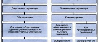
Specific calculations
Let's say you need to make a calculation for a household with an area of 150 square meters.
m. If we assume that 100 watts of heat are lost per 1 square meter, we get: 150x100 = 15 kW of heat loss. How does this value relate to the circulation pump? With heat losses, there is a constant consumption of thermal energy. To maintain the temperature in the room, more energy is required than to compensate for it.
To calculate a circulation pump for a heating system, you should understand what its functions are. This device performs the following tasks:
- create a water pressure sufficient to overcome the hydraulic resistance of the system components;
- pump through pipes and radiators the volume of hot water required to effectively warm up the household.
That is, in order for the system to work, you need to adjust the thermal energy to the radiator. And this function is performed by the circulation pump. It is this that stimulates the supply of coolant to heating devices.
The next task: how much water, heated to the required temperature, must be delivered to the radiators over a certain period of time, while compensating for all heat loss? The answer is expressed in the amount of coolant pumped per unit time. This will be called the power that the circulation pump has. And vice versa: you can determine the approximate coolant flow rate based on the pump power.
Data needed for this:
- The amount of thermal energy required to compensate for heat loss. For this household with an area of 150 sq. meters this figure is 15 kW.
- The specific heat capacity of water, which acts as a coolant, is 4200 J per 1 kilogram of water, for every degree of temperature.
- Temperature delta between the water supply from the boiler and the last section of the return pipeline.
It is believed that under normal conditions this last value does not exceed 20 degrees. On average they take 15 degrees.
The formula for calculating the pump is as follows: G/(cx(T1-T2))= Q
- Q is the coolant consumption in the heating system. So much liquid at a certain temperature must be delivered to the circulation pump to the heating devices per unit of time in order for heat loss to be compensated. It is not advisable to purchase a device that has more power. This will only lead to increased electricity consumption.
- G - heat loss at home;
- T2 is the temperature of the coolant flowing from the boiler heat exchanger. This is exactly the temperature level that is needed to heat the room (about 80 degrees);
- T1 - temperature of the coolant in the return pipeline at the entrance to the boiler (most often 60 degrees);
- c is the specific heat capacity of water (4200 Joules per kg).
When calculated using the above formula, the figure is 2.4 kg/s.
Now we need to translate this indicator into the language of circulation pump manufacturers.
1 kilogram of water corresponds to 1 cubic decimeter. One cubic meter is equal to 1000 cubic decimeters.
It turns out that the pump pumps the following volume of water per second:
2.4/1000=0.0024 cubic meters m.
Next you need to convert seconds to hours:
0.0024x3600=8.64 cubic meters m/h.
Calculation of heat losses
This calculation can be performed independently, since the formula has long been derived. However, calculating heat consumption is quite complex and requires consideration of several parameters at once.
To put it simply, it comes down only to determining the loss of thermal energy, expressed in the power of the heat flow, which is radiated into the external environment by each square meter of the area of the walls, ceilings, floors and roofs of the building.
Related article: Making LED lamps with your own hands
If we take the average value of such losses, they will be:
- about 100 watts per unit area - for average walls, for example, brick walls of normal thickness, with normal interior decoration, with double-glazed windows installed;
- more than 100 Watts or significantly more than 100 Watts per unit area, if we are talking about walls with insufficient thickness, not insulated;
- about 80 watts per unit area, if we are talking about walls with sufficient thickness, having external and internal thermal insulation, with installed double-glazed windows.
To determine this indicator with greater accuracy, a special formula has been developed in which some variables are tabular data.
Great Encyclopedia of Oil and Gas
Speed - movement - coolant
The speeds of movement of thermal carriers in innovative devices in most cases provide a turbulent mode of flow movement, in which, as everyone knows, there is an active exchange of momentum, energy and mass between sections located in the vicinity of the flow due to chaotic turbulent pulsations. According to its physical essence, turbulent heat transfer is considered convective transfer.
The speed of movement of the coolant in the pipelines of heating systems with convective circulation in most cases is 0 05 - 0 2 m / s, and with artificial circulation - 0 2 - 1 0 m / s.
The speed of movement of the heat carrier affects the drying speed of the brick. From the above studies it follows that the acceleration of drying bricks by increasing the speed of movement of the heat carrier is more noticeable when this speed is more than 0 5 m / sec. During the first drying period, an impressive increase in the speed of movement of the coolant is detrimental to the quality of the brick if the coolant is not wet enough.
The speed of movement of the coolant in the tubes of heat exchangers must be in all operating modes no less than 0-35 m/s with water coolant and no less than 0-25 m/s with non-freezing coolant.
The speed of movement of the coolant in heating systems is determined using hydraulics by calculation and economic considerations.
The speed of movement of heat carriers, determined by the cross-section of the heat exchanger channels, fluctuates over a fairly wide range and, without large inaccuracies, cannot be accepted or set before solving the problem of the type and size of the heat exchanger.
The speed of movement of the coolant w has the maximum effect on heat transfer. The higher the speed, the more intense the heat exchange.
The speed of movement of the heat carrier in the drying channel should not be more than 5 - 6 m/min to avoid the formation of a lumpy surface of the layer for work and too intense a structure. Almost the speed of the coolant is selected within the range of 2 - 5 m / min.
The speed of movement of the coolant in water heating systems is allowed up to 1 - 15 m/s in public and residential buildings and up to three meters/s in industrial premises.
Increasing the speed of movement of the coolant is beneficial only up to a specific limit. If this speed is higher than the appropriate one, the gases will not have time to completely transfer their own heat to the material and will leave the drum at a high temperature.
An increase in the speed of movement of the coolant can also be achieved in elemental (battery) heat exchangers, which is a battery of several heat exchangers gradually connected to each other.
With an increase in the speed of movement of thermal carriers, Re w / / v, the heat transfer rate and the heat flux density qa At also become greater. However, simultaneously with the speed, the hydraulic resistance and power consumption of the pumps pumping the coolant through the heat exchanger increase in proportion to w2. There is a suitable speed value, determined by comparing the increase in heat transfer intensity and the more intense growth of hydraulic resistance with increasing speed.
To increase the speed of movement of the coolant in the annulus, transverse and longitudinal partitions are installed.
Great Encyclopedia of Oil and Gas
Great Encyclopedia of Oil and Gas Speed - movement - thermal carrier The speed of movement of thermal carriers in innovative devices in most cases provides a turbulent mode of flow movement, with
Heat supply standards RF PP 354 dated 05/06/2011 and GOST
On May 6, 2011, a Government Order was issued, which is still in effect today. Based on it, the heating period is determined not so much by the period of the year, but by the ambient temperature outside.
The main heating begins to work under the conditions that the external thermometer shows a mark below 8 ° C, and the cold snap continues for at least several days.
On the sixth day, the pipes already begin to heat the rooms. If warming occurs within the specified time, the heating period is postponed. In all parts of the country, radiators bring joy with their own warmth from mid-autumn and maintain optimal temperatures until the end of April.
If frost has set in and the pipes remain cold, this may be the result of a breakdown in the system. In the event of a global malfunction or unfinished repair work, you will need to use an additional heating device until the breakdown is fixed.
If the difficulty lies in air pockets filling the batteries, then contact the operating company. Within 24 hours after submitting the application, a plumber assigned to the house will arrive and “blow out” the problematic area.
The standard and norms for possible values of ambient temperature are specified in the document “GOST R 51617-200. Housing and communal services. General technical information". The range of air heating in the apartment can vary from 10 to 25 °C, depending on the purpose of each room that is heated.
- Living rooms, which include guest rooms, sleeping rooms, offices and similar, must be heated to 22 °C. This mark may fluctuate up to 20 °C, especially in cold corner rooms. The maximum thermometer value should not exceed 24 °C.
A temperature of 19 to 21 °C is considered suitable, but zone cooling to 18 °C or active heating to 26 °C is permitted.
- The bathroom follows the temperature range of the kitchen. But, the room where the bathtub is installed, or the adjacent plumbing unit, are considered rooms with a very high level of moisture. This part of the living space can heat up to 26 °C and cool down to 18 °C. Although, even at an acceptable permissible value of 20 °C, it is uncomfortable to use the bathroom for its intended purpose.
- A comfortable temperature range for corridors is 18–20 °C. But, reducing the mark to 16 °C is considered quite tolerable.
- Indicators in pantries may be even lower. While 16 to 18°C is a good range, the 12 or 22°C mark is not out of line.
- Upon entering the entrance, a resident of the house has the right to hope for an air temperature of at least 16 °C.
- A person spends only a short time in the elevator, hence the comfortable temperature of only 5 °C.
- The coldest places in high-rise buildings are the basement and attic floor. The temperature here can drop to 4 °C.
Home warmth also depends on the time of day. It is officially recognized that during sleep a person needs a small amount of heat. Based on this, a decrease in temperature in the premises by 3 degrees from 00.00 to 05.00 in the morning is not considered a violation.
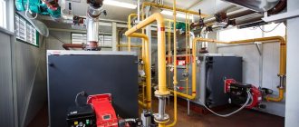
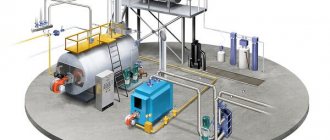
BASIC REQUIREMENTS FOR OPERATION OF BOILER INSTALLATIONS
In accordance with engineering rules, in order to ensure optimal use of the high heat transfer rates of modern boilers, special attention should be paid to the equipment of boiler rooms.
It is not enough to generate a sufficient amount of heat; it is also necessary to transfer it to the consumer.
Adjusting the hydraulic mode of boiler installations is the most important condition for reliable, long-term and efficient operation of both the boilers themselves and the entire heating system as a whole.
When selecting boilers, it is necessary not only to proceed from the required power, but also to take into account the temperature of the return water, the range of permissible coolant flow rates, requirements for changes in flow rate over time, the hydraulic resistance of boilers operating in parallel, as well as a number of other operating parameters.
Their influence on possible disturbances in boiler operation is shown by the following examples.
Water flow through the boiler
Insufficient water consumption can lead to overheating and failure of the boiler, and excessive consumption can lead to its ineffective operation and increased internal corrosion.
The minimum and maximum permissible water flow is indicated. These costs vary depending on boiler models.
Return water temperature
This parameter must be taken into account, since too low a return water temperature can lead to condensation of burnt fuel vapor on the internal parts of the boiler and its rapid corrosion, since the condensate is highly acidic and may contain sulfur compounds.
For example, if the minimum temperature of return water to the boiler is 55 °C, it is necessary to provide sufficient water addition to the boiler from the supply line.
Hydraulic resistance of the boiler, fittings, pipelines
This factor should be taken into account when selecting pumps and when replacing boilers, since modern boilers have increased hydraulic resistance; if you install such a boiler in parallel with old boilers that have low resistance, the main coolant flow will be through them, and the new boiler will not give the expected heat transfer.
Over time, the boiler and pipelines become overgrown with corrosion products, as well as changes in the characteristics of pumps and fittings. This leads to a reduction in coolant costs and, accordingly, to the problems described above.
To ensure the reliability of boiler installations, the following 5 rules must be observed:
RULE #1
:
MINIMUM COOLANT FLOW:
Constantly provide for each boiler, during operation, a minimum coolant flow corresponding to the rated power of the boiler, and the temperature difference between the supply line and the return line of the boiler should be less than 25 ° C;
RULE #2
:
AIR REMOVAL:
Ensure constant and effective air removal under all boiler and piping operating conditions;
Air is essential for life, but it is not valued in heating installations because it promotes corrosion and sludge formation.
There are many sources of air:
This phenomenon relies on a physical principle that is not initially taken into account. So, despite the increased pressure that prevails in the system, air can nevertheless penetrate there: it all depends on its degree of saturation.
When water is heated in a boiler, its absorption capacity decreases, and the opposite effect will be observed: air separates and turns into a gaseous state.
On the contrary, when water is cooled in heating devices, its absorption capacity will increase. The water begins to “pull” air through joints, leaks or pipes, despite the fact that the water pressure exceeds atmospheric pressure.
Conclusion: Under certain conditions of temperature and pressure, a liquid contains more or less dissolved gas.
Air may enter during filling; sometimes water contains up to 15 mg/l of oxygen dissolved in it.
When heated, it is released and goes into gaseous form.
— Expansion tanks are missing, faulty or incorrectly sized. This can create areas of low pressure in heating systems relative to atmospheric pressure.
Air release devices are missing, faulty or incorrectly installed.
Air removal methods:
In all the variety of existing solutions for air separation in installations, 2 main methods can be distinguished, using:
- hydraulic devices:
Gas removal devices: air vents, automatic air vents, absorption devices that allow air to be dissolved in water...
- chemical processes:
The installation can be treated by adding various substances, for example sodium sulfite in an amount of 100 g/m³ for make-up water.
This will require regular monitoring of the sulfite percentage in order to adjust it if necessary.
Before any commissioning of a new installation or after servicing existing networks, it is necessary to thoroughly flush them, filling them with water from the city water supply, and emptying them at the maximum flow rate in order to remove the largest part of the solids that have not settled on the partitions.
Complete water treatment begins with the installation of a water meter in order to monitor the make-up water and know the actual volume of the installation (reading data from the meter when first filling).
This will also be needed when calculating the amount of substances to be added.
Then, it is necessary to soften the make-up water; introduce substances that destroy living organisms; corrosion inhibitors and pH regulators; oxygen reducers; and finally install an effective anti-sludge treatment.
The dosage and toxicity of added substances must always be controlled.
RULE #3
:
WATER LEVEL:
Ensure sufficient water level in the installation;
RULE #4
:
HYDROSTATIC PRESSURE:
Provide the necessary hydrostatic water pressure in the boilers;
Correct calculation of the expansion tank:
- Tank pressure = P>=HS (hydrostatic height).
- Filling pressure = P+ 0.3
Installation of a protective pressure switch.
RULE #5
:
SCALE DEPOSITION:
Take all measures against scale deposits:
- Water meter.
- Water treatment if TH > 125 mg-eq.
- Correctly designed expansion tank.
If oxygen from the air is responsible for corrosion, then water and its components are responsible for scale deposits in heating installations.
In order to find out the properties of water or provide remedies against the negative consequences of its use, you first need to know the composition of this water.
Only those quantities used for make-up water are taken into account.
These are: TH, pH and resistivity
.
— General hydrometric indicator or total TH (mg-equiv.):
Measures the total amount of dissolved calcium (Ca++) and magnesium (Mg++) salts. These two elements, in sulfates and carbonates, form most of what is called “scale.”
or
“limestone”
.
Mechanisms of scale formation
.
When water heats up, gas microbubbles appear. They are released from water as the temperature increases, particularly from 55° C. This gas is released oxygen. But starting at 55°C, the dissociation of bicarbonates begins to form CO2. At the moment of formation and release of CO2, it is noted that the carbon balance is disturbed. When the balance is disturbed, calcium and magnesium, which were part of the bicarbonates, begin to precipitate in the form of scale.
In heating installations, O2 and CO2 gases will be removed by air vents, and carbonate deposits will occur at the hottest point of the installation.
Allowed at
TH >= 125 mEq.
use water without softening if there are no abnormal inflows: additions or emptyings.
Classification of water by TH ( mg-eq.) :
- 0 + 25 TH: soft water;
- 25 + 75 TH: medium hard water;
- 75 + 125 TH: hard water;
- over 125 TH: very hard water.
— pH measurement:
Allows you to determine the acidity or alkalinity of water with an intermediate equilibrium zone, where the pH is called “neutral”. pH
inversely proportional to temperature.
This measurement is mandatory for water in communal heating installations with a power of more than 350 kW.
Recommended values vary depending on the metals present in the installation.
Approximate values for pH at 20°C:
- Steel installations: 9.5 < pH < 10.5
- Installations with aluminum parts: 7.5 < pH < 8.5
- Cast iron boilers: 7.5 < pH < 10.5.
Specific resistance of water
ρ
Water (pure) resists the passage of electric current:
Natural and drinking waters contain dissolved salts and gases, thus reducing resistance.
Low-mineralized water with ρ > 4,500
Ω cm
risks being a “good solvent,” that is, destroying the metal and causing corrosion.
On the contrary, water containing a large amount of dissolved salts and gases will be a “conductor” of electric current ( ρ < 1,500
Ω /cm
). This means that there is a risk of scale deposits as well as corrosion due to the “ease” of electrical current passing through water and, for example, if the installation contains various metals.
Water treatment agents against scale deposits:
As in the case of water treatment against air, 2 types of methods against scale deposits can also be distinguished:
hydraulic devices:
(counters);
To prevent scale formation, it is necessary to avoid adding water, and to do this, it is necessary to prevent leaks.
The main element is the make-up water meter.
All boiler rooms must be equipped with it to control the magnitude of these additions.
Table for determining the amount of make-up water depending on its hardness.
| Total power – Q , (Gcal/h) | hardness – TN, (mg-eq.) | Maximum amount of make-up water – Vmax , ( m³ ) |
| Q ≤ 0.1 | No limits | No limits |
| 0.1< Q ≤ 0.35 | ≤ 100 | Vmax = 3*Installation volume |
| 0.35< Q ≤1.0 | ≤ 75 | |
| 0.1< Q ≤ 0.35 | > 100 | Vmax = 0.313*( Q /TH) |
| 0.35< Q ≤1.0 | > 75 | |
| 1.0< Q | —- |
If the quantity and hardness of water do not meet the above requirements, it is necessary to use water softening devices.
— chemical processes:
Sodium exchange softener -
Calcium and magnesium ions dissolved in water are replaced in appropriate amounts by sodium ions.
Sodium exchange is driven by ion exchange resins, which come in the form of small porous beads.
However, it should be noted that highly softened water (0 mg-equiv. TH) becomes aggressive.
The element responsible for this is free carbon dioxide. Consequently, additional water treatment with corrosion inhibitors becomes necessary.
Water treatment against scale deposits
If a softener is not available, then it is necessary to use water treatment to prevent scale formation. For this purpose, liquid substances are used, introduced using metering pumps or injection chambers.
There are many types of anti-scale water treatment, depending on the degree of protection required.
Water treatment devices additionally add dispersants - these are substances that prevent sludge deposition (on pipes or at the bottom of boilers, in radiators).
Monitoring water in the system after water treatment
Control of water in circuits:
Changing the parameters of the circuit water in relation to the parameters of the introduced makeup water will help identify possible anomalies.
Thus:
- The pH
of a closed circuit with water treatment generally takes values from 9 to 10, except in the case of the presence of aluminum or aluminum alloys. - A decrease in TH and TAC
relative to the make-up water indicates the formation of calcium ion precipitate in the form of sludge or scale. - The presence of TH
or excess chlorides when using a water softener indicates that it is not working properly. - The presence of dissolved iron or copper and especially an increase in their concentrations over time indicates corrosion of the corresponding metals.
- Significant chloride content and increased conductivity indicate increased concentration of dissolved salts, which may be caused by water loss due to evaporation.
- An increased bacterial content means the proliferation of microorganisms with the formation, in general, of scale, the appearance of odors and an increased risk of corrosion.
- A low pH in the presence of an antifreeze additive indicates its decomposition into acids.
In addition to the three physical quantities characterizing the filling water, i.e. pH, TH and specific conductivity, it is added:
- TAC
, which measures the concentration of bicarbonates in water.
It indicates the tendency
of water to form scale. - The content of dissolved metals (iron, copper, aluminum), an increase in which indicates corrosion of the corresponding metals.
- Chloride content, which may indicate contamination from soldering fluxes.
All these values allow you to diagnose the water in the circuit.
Water speed in the heating system
In order for the water heating system to function correctly, it is necessary to ensure the required speed of the coolant in the system. If the speed is low, heating of the room will be very slow and distant heating devices will be significantly colder than nearby ones. On the contrary, if the speed of the coolant is very high, then the coolant itself will not have time to warm up in the boiler, and the temperature of the entire heating system will be lower. A noise parameter will also be added. As you can see, the speed of the coolant in the heating system is a very basic parameter. Let’s take a closer look at what the most appropriate speed should be.
Heating systems where convective circulation occurs generally have a relatively low coolant velocity. The pressure difference in the pipes is achieved by the correct placement of the boiler, expansion tank and the pipes themselves - direct and return. Only a good calculation before installation work makes it possible to achieve the correct, uniform movement of the coolant. But still, the inertia of heating systems with convective circulation of liquid is quite high. The result is slow heating of rooms, low efficiency. The main advantage of such a system is the greatest independence from electrical energy; there are no electric pumps.
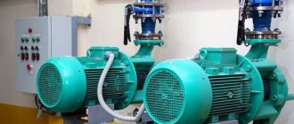
Very often, homes use a heating system with forced circulation of a coolant. An important element of such a system is a circular pump. Specifically, it accelerates the movement of the coolant; the speed of the liquid in the heating system depends on its parameters.
What affects the speed of the coolant in the heating system:
- schematic diagram of the heating system, - type of coolant, - power, efficiency of the circulation pump, - what material the pipes are made of and their diameter, - absence of air pockets and blockages in the pipes and radiators.
For a private house, it would be more correct to have a coolant velocity in the range of 0.5 – 1.5 m/s. For administrative buildings - no more than two meters/s. For industrial premises – no more than three meters/s. The upper limit of the coolant velocity is selected, for the most part, due to the noise level in the pipes.
Many circular pumps have a fluid flow rate regulator, so you can choose the best one specifically for your system. It is also necessary to select the pump itself correctly. There is no need to take it with a large power reserve, as there will be greater power consumption. If the heating system is long, has a large number of circuits, number of floors, and so on, it is better to install several pumps of lower productivity. For example, install a pump separately on a heated floor on the second floor.
Water speed in the heating system
Water speed in the heating system In order for the water heating system to function correctly, it is necessary to ensure the required speed of the coolant in the system. If the speed is low,
Determining the flow rate (G, m 3 / hour) of the coolant when choosing a pump
The starting point for selecting a pump is the amount of heat that the house loses. How to find out? To do this, you need to calculate heat loss.
This is a complex engineering calculation that requires knowledge of many components. Therefore, in this article we will omit this explanation, and as a basis for the amount of heat loss we will take one of the common (but far from accurate) methods used by many installation companies.
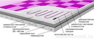
Its essence lies in a certain average loss per 1 m 2. This value is arbitrary and amounts to 100 W/m2 (if a house or room has uninsulated brick walls, and even those of insufficient thickness, the amount of heat lost by the room will be significantly greater. And vice versa, if the enclosing structures of the house are made using modern materials and have good thermal insulation, heat loss will be reduced and can be 90 or 80 W/m2).
So, let's say you have a house with an area of 120 or 200 m2. Then the amount of heat loss we have agreed upon for the entire house will be:
120 * 100 = 12000 W or 12 kW.
What does this have to do with the pump? The most direct.
The process of heat loss in the house occurs constantly, which means that the process of heating the premises (compensation for heat loss) must be ongoing.
Imagine that you have no pump, no pipelines. How would you solve this problem?
To compensate for heat loss, you would have to burn some type of fuel in a heated room, for example, firewood, which is basically what people have been doing for thousands of years.
But you decided to give up firewood and use water to heat your house. What would you have to do? You would have to take a bucket(s), pour water into it and heat it over a fire or gas stove until it boils. After this, take the buckets and carry them into the room where the water would give off its heat to the room. Then take other buckets of water and place them again on the fire or gas stove to heat the water, and then carry them into the room to replace the first ones. And so on ad infinitum.
Today the pump does this job for you. It forces water to move to a device where it is heated (boiler), and then, to transfer the heat stored in the water through pipelines, it directs it to heating devices to compensate for heat loss in the room.
The question arises: how much water is needed per unit of time, heated to a given temperature, to compensate for heat loss at home?
How to calculate this?
To do this you need to know several quantities:
- the amount of heat that is necessary to compensate for heat losses (in this article we took as a basis a house with an area of 120 m2 with heat losses of 12000 W)
- specific heat capacity of water equal to 4200 J/kg * o C;
- the difference between the initial temperature t 1 (return temperature) and the final temperature t 2 (supply temperature) to which the coolant is heated (this difference is denoted as ΔT and in heating engineering for calculating radiator heating systems is defined as 15 - 20 o C).
These values must be substituted into the formula:
G = Q / (c * (t 2 – t 1 )), where
G – required water flow in the heating system, kg/sec. (This parameter must be provided by a pump. If you buy a pump with a lower flow rate, it will not be able to provide the amount of water necessary to compensate for heat losses; if you buy a pump with an increased flow rate, this will lead to a decrease in its efficiency, excessive energy consumption and high initial costs) ;
Q – amount of heat W required to compensate for heat loss;
t 2 – final temperature to which the water needs to be heated (usually 75, 80 or 90 o C);
t 1 – initial temperature (temperature of the coolant, cooled by 15 – 20 o C);
c is the specific heat capacity of water, equal to 4200 J/kg * o C.
We substitute the known values into the formula and get:
G = 12000 / 4200 * (80 – 60) = 0.143 kg/s
This coolant flow rate per second is necessary to compensate for the heat losses of your house with an area of 120 m2.
In practice, they use the flow of water moved for 1 hour. In this case, the formula, after undergoing some transformations, takes the following form:
G = 0.86 * Q / t 2 – t 1 ;
G = 0.86 * Q / ΔT, where
ΔT is the temperature difference between the supply and return (as we have already seen above, ΔT is a known value that is initially included in the calculation).
Coolant speed
Schematic calculation
There is a minimum speed of hot water inside the heating system at which the heating itself operates optimally. This is 0.2-0.25 m/s. If it decreases, then air begins to be released from the water, which leads to the formation of air jams. Consequences - the heating will not work and the boiler will boil.
This is the lower threshold, and as for the upper level, it should not exceed 1.5 m/s. Exceeding it threatens the appearance of noise inside the pipeline. The most acceptable indicator is 0.3-0.7 m/s.
If you need to accurately calculate the speed of water movement, you will have to take into account the parameters of the material from which the pipes are made. Especially in this case, the roughness of the internal surfaces of the pipes is taken into account.
For example, hot water moves through steel pipes at a speed of 0.25-0.5 m/s, through copper pipes 0.25-0.7 m/s, through plastic pipes 0.3-0.7 m/s.
Purpose and progress of the calculation
Of course, you can turn to specialists for results or use an online calculator, of which there are plenty on all sorts of Internet resources. But the first costs money, and the second may give incorrect results and still needs to be checked.
So it’s better to be patient and get down to business yourself. It must be understood that the practical purpose of hydraulic calculation is to select the flow sections of pipes and determine the pressure drop in the entire system in order to correctly select the circulation pump.
Note. Giving recommendations for performing calculations, it is assumed that thermal calculations have already been made and radiators have been selected according to power. If not, then you will have to go the old way: take the thermal power of each radiator according to the quadrature of the room, but then the accuracy of the calculation will decrease.
The general calculation scheme looks like this:
- preparation of an axonometric diagram: when the calculation of heating devices has already been completed, their power is known, it must be plotted on the drawing near each radiator;
- determination of coolant flow and pipeline diameters;
- calculation of system resistance and selection of a circulation pump;
- calculation of the volume of water in the system and the capacity of the expansion tank.
Any hydraulic calculation of a heating system begins with a diagram drawn in 3 dimensions for clarity (axonometry). All known data is plotted on it; as an example, let’s take the section of the system shown in the drawing:
Selecting a Key Contour
The hydraulic arrow separates the boiler and heating circuits
Here we need to consider two schemes separately - one-pipe and two-pipe. In the first option, the calculation must be carried out through the most loaded riser, where a decent number of radiators and shut-off valves are installed.
In another option, the busiest circuit is selected. Actually, it is based on this that calculations need to be made. All other circuits will have much less hydraulic resistance.
For example, if a horizontal pipe junction is considered, then the busiest ring of the basement is selected. By load they know the heat load.
Coolant flow
Coolant flow
To show how hydraulic heating calculations are performed, let us take as an example a simple heating circuit, which includes a heating boiler and heating radiators with kilowatt heat consumption. And there are 10 such radiators in the system.
Here it is important to correctly divide the entire scheme into sections, and at the same time strictly adhere to one rule - the diameter of the pipes in each section should not change. So, the first section is the pipeline from the boiler to the first heating device
The second section is the pipeline between the first and second radiators. And so on
So, the first section is the pipeline from the boiler to the first heating device. The second section is the pipeline between the first and second radiators. And so on.
How does heat transfer occur, and how does the temperature of the coolant decrease? Getting into the first radiator, the coolant gives off part of the heat, which is reduced by 1 kilowatt. It is in the first section that hydraulic calculations are made at 10 kilowatts. But in the second section it’s already below 9. And so on with a decrease.
There is a formula by which you can calculate the coolant flow:
G = (3.6 x Qch) / (c x (tr-to))
Qch is the calculated thermal load of the area. In our example, for the first section it is 10 kW, for the second 9.
c is the specific heat capacity of water, a constant indicator equal to 4.2 kJ/kg x C;
tr is the temperature of the coolant at the entrance to the site;
to is the temperature of the coolant at the exit from the site.
Summarizing
So, calculating the coolant in the heating system shows how much water is required by the entire heating system to maintain the house at normal temperature. The same figure is conditionally equal to the power of the pump, which, in fact, will deliver the coolant to the radiators, where it will release part of its thermal energy into the room.
It is worth noting that the average power of the pumps is approximately 10 cubic meters per hour, which gives a small margin, since the thermal balance must not only be maintained, but sometimes, at the owner’s request, the air temperature must be increased, which, in fact, requires additional power .
Experienced experts recommend purchasing a pump that is approximately 1.3 times more powerful than required. Speaking about a gas heating boiler, which, as a rule, is already equipped with such a pump, you should pay attention to this parameter.
Selecting the appropriate coolant speed in a residential heating system
There is a one-level apartment from inside a five-story cottage house. The entire area is 113 sq. m. The walls from the outside are insulated. Heat supply is gas, from a two-stage boiler "Ariston UNO". Heat supply distribution is manifold (star). There are no heated floors; there are heating devices in every room. The boiler is controlled by a room thermostatic valve - a weekly programmer located in the coldest room.
The boiler pump has a three-level adjustment of the speed of the coolant in the system.
Question! How to choose the best setting for the coolant speed so that the system operates with the greatest savings?
PS Experiments with different speeds of the coolant in this apartment show that with any of the three options provided, all heating devices work well. At high speed there were no visible noise effects.
Hedgehog, with a decrease in speed, the heat transfer of heating devices decreases, and the flow/return difference increases. The appropriate value for this difference for a boiler is 20 degrees. Measure this temperature difference at different speeds.
Increase the speed - increase the background noise
Ezhachok wrote: Question! How to choose the best setting for the coolant speed so that the system operates with the greatest savings?
Is the boiler condensing or non-condensing? Are the pipes polymer or iron? The answer to your question may depend on this.
Hydraulic calculation of heating systems. Heat calculation (calculation of insulation) of apartments and houses.
Ezhachok wrote: Question! How to choose the best setting for the coolant speed so that the system operates with the greatest savings?
Speed is already a derivative of the coolant flow rate and the pipe diameter. Those. According to important conditions, the actual global flow of the coolant is primary.
To equip the highest efficiency of the boiler, it is necessary to ensure the flow rate of the coolant so that the heat mode of the boiler is:
Regarding mounted boilers and floor-mounted boilers with counter flow (volatile).
For a non-condensing boiler: 1a) Supply/return - 80/60 degrees for pipes made of metal in the system. 1b) 70/60 - for polypropylene pipes.
For a condensing type boiler: 2a) Maximum 80/60 for pipes made of metal with a reduction in the mode under the control of weather-dependent boiler automation to 50/30. The lower the return flow for a cold five-day period, the greater the gas savings. For example, to save gas, you can design a boiler mode for a cold five-day period of 70/50 with a decrease in the mode in the off-season to 40/30. 2b) Maximum 70/50 - for polypropylene pipes. Lowering the schedule, as in the previous paragraph, will make it possible to save gas.
P.S. And in order to avoid noise in the pipes and fittings, it is necessary not to exceed the maximum possible speeds of the coolant in the pipes (you can look at the linear resistance of no more than 150-200 Pa/meter), and not to exceed the maximum possible pressure drops on the fittings (for thermal valves no higher 30-60 kPa depending on the manufacturer and brand).
Hydraulic calculation of heating systems. Heat calculation (calculation of insulation) of apartments and houses.
Selecting the appropriate coolant speed in a residential heating system
There is a one-level apartment from inside a five-story cottage house. The entire area is 113 sq. m. The walls from the outside are insulated. Gas heat supply from a two-stage boiler "Ariston UNO" - Mastergrad Forum
Accurate calculation of heat losses at home
To quantify the heat loss of a house, there is a special value called heat flow, and it is measured in kcal/hour. This value physically shows the heat consumption that is given off by the walls to the environment under a given thermal regime inside the building.
This value depends directly on the architecture of the building, on the physical properties of the materials of the walls, floor and ceiling, as well as on many other factors that can cause the weathering of warm air, for example, improper installation of the thermal insulation layer.
So, the amount of heat loss of a building is the sum of all heat losses of its individual elements. This value is calculated using the formula: G = S*1/ Po*(Tv-Tn)k, where:
- G is the desired value, expressed in kcal/h;
- Po is the resistance to the process of thermal energy exchange (heat transfer), expressed in kcal/h, this is sq.m*h*temperature;
- Tv, Tn - air temperature indoors and outdoors, respectively;
- k is a reducing coefficient, which is different for each thermal barrier.
It is worth noting that since the calculation is not made every day, and the formula contains temperature indicators that change constantly, it is customary to take such indicators in average form.
This means that average temperature indicators are taken, and for each individual region this indicator will be different.
So, now the formula does not contain unknown terms, which allows for a fairly accurate calculation of the heat losses of a particular house. It remains to find out only the reduction factor and the value of Po - resistance.
Both of these values, depending on each specific case, can be found out from the corresponding reference data.
Some values of the reduction factor:
- floor on the ground or wooden joists - value 1;
- attic floors, in the presence of a roof with roofing material made of steel, tiles on a sparse sheathing, as well as roofing made of asbestos-cement, non-attic roofing with ventilation, - value 0.9;
- the same floors as in the previous paragraph, but arranged on a continuous flooring - value 0.8;
- attic floors, with a roof, the roofing material of which is any rolled material - value 0.75;
- any walls that separate a heated room from an unheated one, which, in turn, has external walls - value 0.7;
- any walls that separate a heated room from an unheated one, which, in turn, does not have external walls - value 0.4;
- floors installed above cellars located below the level of the external ground - value 0.4;
- floors installed above cellars located above the level of the external ground - value 0.75;
- ceilings that are located above basements that are located below the level of the external soil or above by a maximum of 1 m - value 0.6.
Based on the cases described above, you can roughly imagine the scale, and for each specific case that is not included in this list, you can independently select a reduction factor.
Related article: Sequence of building a house made of timber with your own hands
Some values for heat transfer resistance:
The resistance value for solid brickwork is 0.38.
- for ordinary solid brickwork (wall thickness approximately 135 mm) the value is 0.38;
- the same, but with a masonry thickness of 265 mm - 0.57, 395 mm - 0.76, 525 mm - 0.94, 655 mm - 1.13;
- for solid masonry with an air gap, with a thickness of 435 mm - 0.9, 565 mm - 1.09, 655 mm - 1.28;
- for solid masonry of decorative bricks for a thickness of 395 mm - 0.89, 525 mm - 1.2, 655 mm - 1.4;
- for continuous masonry with a thermal insulation layer for a thickness of 395 mm - 1.03, 525 mm - 1.49;
- for wooden walls made of individual wooden elements (not timber) for a thickness of 20 cm - 1.33, 22 cm - 1.45, 24 cm - 1.56;
- for walls made of timber with a thickness of 15 cm - 1.18, 18 cm - 1.28, 20 cm - 1.32;
- for an attic floor made of reinforced concrete slabs with insulation when their thickness is 10 cm - 0.69, 15 cm - 0.89.
Having such tabular data, you can begin to perform an accurate calculation.
The speed of water movement in the pipes of the heating system.
During the lectures we were told that the appropriate speed of water movement in a water supply system is 0.8-1.5 m/s. On some sites I see something similar (about the largest one, one and a half meters per second).
However, the manual says to accept losses per linear meter and speed - according to the application in the manual. The speeds there are completely different, the highest that is on the plate is just 0.8 m/s.
And in the textbook I came across an example of a calculation where the speeds do not exceed 0.3-0.4 m/s.
So what is the essence? How to take it in general (and how in reality, at work)?
I am attaching a screenshot of the sign from the manual.
Thank you all in advance for your answers!
What do you want? Should you find out “military secrets” (as you really need to do), or pass the coursework? If only a course student - then according to the training manual, which the teacher wrote and does not know anything else and does not want to know. And if you do it right
, will not accept it either.
0.036*G^0.53 - for heating risers
0.034*G^0.49 - for mm mains of the branch, until the load decreases to 1/3
0.022*G^0.49 - for the end sections of a branch with a load of 1/3 of the entire branch
In the coursework, I calculated it according to the manual. But I wanted to find out how the atmosphere was going.
To put it differently, what appears in the textbook (Staroverov, M. Stroyizdat) is also not correct (speeds from 0.08 to 0.3-0.4). But maybe there is only an example of calculation.
Offtop: In other words, you also confirm that essentially the old (relatively) SNiPs are not at all inferior to the new ones, and in some cases much better. (many teachers tell us about this. In general, the dean of the PSP says that their new SNiP in most cases contradicts both the laws and himself).
But as a rule, everything was explained.
and the calculation to reduce diameters along the flow seems to save materials. but increases labor costs for the installation process. If labor is cheap, it might make sense. if the labor is expensive, there is no point. And if over a long length (heating main) changing the diameter is beneficial, fiddling with these diameters within the house is pointless.
and there is also the concept of hydraulic stability of the heating system - and here the ShaggyDoc schemes win
We disconnect each riser (upper wiring) from the main line with a valve. I've seen that double adjustment taps are installed immediately after the valve. Better?
And how to disconnect the heating devices themselves from the connections: using valves, or installing a double adjustment tap, or both? (in other words, if such a valve could completely close the pipeline, then a valve would not be required at all?)
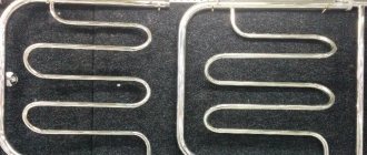
And for what purpose are pipeline parts insulated? (designation - spiral)
The heating system is two-pipe.
I need to find out exactly by the supply pipeline, the question is above.
We have an indicator of local resistance to the flow input with a turn. We use it at the entrance through the louvered grille to the vertical channel. And this indicator is 2.5 - which is a lot.
To put it another way, how can you invent something to free yourself from this? One of the exits is if the grille is “in the ceiling”, and then there will be no turning entrance (although it will still be small, since the air will be drawn along the ceiling, moving in a horizontal position, and move towards this grille, turning in a vertical direction , however, logically this should be less than 2.5).
You can't put bars in the ceiling in an apartment building, neighbors. and in a single-apartment apartment, the ceiling will be unattractive with bars, and debris can get in. In other words, the problem cannot be solved this way.
I often drill, then plug
Take the heating capacity and the initial temperature from the final temperature. According to this information, you can reliably calculate
speed. It will most likely be a maximum of 0.2 m\S. High speeds - a pump is required.
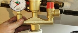
Circulation pump calculation
Selection and calculation of the pump consists of finding out the pressure loss of the coolant flowing throughout the entire pipeline network. The result will be a figure showing how much pressure the circulation pump should develop in order to “push” water through the system. This pressure is calculated using the formula:
P = Rl + Z, where:
- P – pressure loss in the pipeline network, Pa;
- R – specific friction resistance, Pa/m;
- l – pipe length in one section, m;
- Z – pressure loss in local resistances, Pa.
Note. Two-pipe and one-pipe heating systems are calculated in the same way, according to the length of the pipe in all branches, and in the first case, the forward and return lines.
This calculation is quite cumbersome and complex, while the value of Rl for each section can be easily found using the same Shevelev tables. In the example, the blue circle marks the values of 1000i in each section; it only needs to be recalculated along the length of the pipe. Let's take the first section from the example, its length is 5 m. Then the friction resistance will be:
Rl = 26.6 / 1000 x 5 = 0.13 Bar.
We also calculate all sections of the associated heating system, and then summarize the results. It remains to find out the value of Z, the pressure drop in local resistances. For the boiler and radiators, these numbers are indicated in the product passport. For all other resistances, we recommend taking 20% of the total friction losses Rl and summing all these indicators. We multiply the resulting value by a safety factor of 1.3, this will be the required pump pressure.
You should know that pump performance is not the capacity of the heating system, but the total water flow through all branches and risers. An example of its calculation is presented in the previous section, but to select a pumping unit, you also need to provide a reserve of at least 20%.