Common mistakes when installing a boiler
| Consequences | |
| The installation is carried out in violation of the requirements for installation and piping of the boiler. | The operation of the boiler will not correspond to the declared technical characteristics and indicators. Premature boiler failure and wear of components. Breaks in the heating system pipeline. |
| Installation of a chimney in violation of the stated requirements. | Lack of draft in the chimney, formation of condensation and air lock in the chimney, unstable combustion of fuel in the boiler, formation of a high concentration of carbon monoxide. Too strong a draft can lead to overheating of the boiler. |
| Pouring a concrete screed for the boiler base of insufficient thickness (less than 10 cm) onto a wooden floor (floor made of combustible materials). | Fire of wooden structures under a concrete foundation. |
Checking the serviceability of the sling boiler
Before using the boiler permanently, it is necessary to test its serviceability. This is necessary to ensure that the boiler can be operated in a safe manner in the future.
So, you will need to fill up to a third of the barrel of the device with firewood. It is covered with a lid on top, and before that you need to throw a match into the barrel so that the fire begins to flare up. For better ignition, be sure to add kerosene there.
Ideally, the wood should ignite immediately. There should be no draft, no smoke, no smell. If any of the above is observed, then you should not use such a boiler. It is highly likely to harm the owners of the house. However, if everything was done correctly, then there should not be such problems.
The specified amount of firewood is enough to heat a small room for a day.
Installing a chimney clamp
To adjust the draft and remove vibration (this phenomenon is observed when there is excessive draft through the chimney), a clamp is used. The clamp is installed on the outlet pipe of the boiler chimney. To adjust the draft, the clamp must be moved to the side, opening or closing the holes in the boiler chimney pipe. When installing a chimney, it is strictly forbidden to cover the draft adjustment holes with a pipe.
Curved metal plates are necessary to maintain stable combustion of fuel in the boiler furnace and increase the efficiency of the boiler, as well as to clean the inside of the boiler in case of soot accumulation. After installing the boiler, they must be installed through the slot above the top door, between the air heating chamber and the inner shell of the boiler. By bringing the plates together or spreading them apart, you can regulate the required draft in the boiler for more economical operation of the boiler.
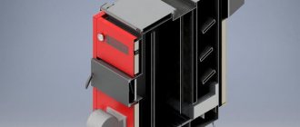
How do Stropuva boilers work?
Let's see how it is customary to start a traditional solid fuel boiler. First, we ignite small chips, and when they take up the flame, we begin to throw full-fledged firewood into the firebox. Our heat source is located below, under the wood stack. This is where the combustion spreads. As a result, the firewood burns out in a matter of hours, and a lot of thermal energy often flies away into the chimney.
Stropuwa boilers are built on the top combustion principle. In this way they are similar to Bubafonya wood stoves - here the wood is lit from above, not from below. The prototype of these furnaces were Stropuva boilers, which have a similar operating principle. Depending on the power of the selected unit, the combustion duration can be up to several days.
The Stropuwa boiler consists of the following elements:
- Combustion chamber – starts from the very bottom of the equipment.
- Heat exchanger – here a “jacket” of the “pipe-in-pipe” type is used. The coolant flowing through it ensures efficient heat intake and transfer to the heating system.
- Air distributor - it is located above the combustion zone and supplies air to it.
- Draft regulator – allows you to adjust the heating temperature of the coolant.
- Air heating chamber - it is responsible for heating the air masses supplied to the combustion zone. This design ensures efficient combustion of wood.
Air is taken in through a damper, combustion products are removed through a pipe in the rear (the chimney is connected to it). There are two doors in the front part - for loading fuel and removing ash.
The Stropuva solid fuel boiler has a long burning time. On one load it can work for up to several days - it all depends on the heated area, the current operating mode and the thermal power of the unit. Dried firewood, pellets, fuel briquettes or coal are used as fuel. According to the manufacturer, the burning time on coal is up to 5 days.
Installing a bi-thermal draft regulator
The operating principle of a bi-thermal draft regulator is based on the fact that when the boiler body heats up and expands, the body itself closes or closes the damper (1) using the damper lever (4), and when cooled, it contracts and opens. After delivery of the boiler, remove the shipping tape, check the presence of the draft regulator parts: damper (1), support bolt with ring (2), support rod (3) and damper lever (4).
Insert the damper lever (4) with the hole into the metal needle located at the end of the support rod installed on the boiler body. Place the support bolt with ring (2) into the recess of the damper lever (4).
Adjustment example
Check whether the flap (1) completely covers the hole (5), and whether the bolt holding it is loose (do not tighten it under any circumstances). By turning the support bolt, install the damper at a distance of 3–5 cm from the air supply hole and only then light the boiler. As the metal and water heat up, the boiler cylinder expands and lowers the damper (1). If the temperature according to the thermometer readings is below 70 °C, open the damper (1) slightly using the support bolt with ring (2) clockwise to raise the temperature; if the temperature according to the thermometer readings is above 85 °C, close the damper (1) using support bolt with ring (2), thereby you will set the maximum value of the coolant temperature in the boiler. Further maintenance of the temperature in a given range will be carried out using a bi-thermal draft regulator in automatic mode.
Attention! Check the fit of the valve (1) to the air supply hole (5), in the closed position there should be no gaps between them.
Installation and installation of the Stropuva S20 boiler
The Stropuva S20/S20U/S10 boiler is installed in premises that meet state requirements for boiler room premises. The height of the room in which the device will be installed must be at least 215 cm.
The floor must be concrete (at least in the place where the boiler will stand). The room must be isolated from heated living spaces, and it must have a vertical ventilation duct and a window or hole in the external wall so that outside air can easily penetrate the boiler and the ventilation duct.
Using a mirror, the inside of the chimney is inspected through the chimney cleaning hole.
The chimney must be clean. There should be no fittings or bird's nests and no unclosed openings into hollow ceilings or adjacent shafts.
It is checked whether there are any holes in the chimney from the outside through which parasitic air can penetrate, cooling the chimney and reducing the draft in it. All openings and joints in the chimney must be sealed.
If there are internal holes in the chimney in the ceilings or adjacent shafts and it is impossible to seal them, you need to insert an oval or cylindrical liner made of stainless steel (rectangular liners are unreliable due to holes formed at the joints due to temperature changes).
The Stropuva S 20 boiler is installed directly on a concrete floor, and the resulting gaps between the floor and the boiler are closed with heat-resistant material (silicone (180˚C) or a solution of lime and cement with sand or other materials).
The boiler can be placed on a concrete bottom for installation with a sealing rope.
When carrying the unit, its parts are sometimes deformed, so after installing it in the chimney and closing all the doors, as well as the openings for cleaning the chimney, check the operation of the upper damper, whether it is adjacent to the surface of the air supply opening, as well as the tightness of the doors using a candle flame or matches.
Standards and requirements for installation of the Stropuva S20/S20U boiler
Chimney requirements
The diagonal of the chimney opening may be 10% less than indicated in the basic technical data, but not more than twice.
Setting the air supply regulator (under the grate)
The air damper, which allows air to pass under the grate, is controlled using the air supply regulator located in the upper part of the boiler. The air supply regulator consists of: a handle (screw that fixes the position of the damper) and a step (comb) for setting the opening of the damper.
When firing with wood, move the handle to position “0”, when burning with pellets, move the handle to position “1”, when burning with coal, move the handle to position “2”, if there is a strong draft in the chimney when burning with coal, it is possible to move the switch to position “1” .
Guide to self-assembly of a Stropuva boiler
Before starting work, prepare the necessary equipment for this.
You won’t need any extremely difficult to use tools or hard-to-find materials. However, it is better to collect everything in advance so as not to be distracted by searching for missing elements in the future.
Stropuva boiler assembly kit
- Metal barrel. Use a large container with a capacity of 200 liters or more.
- Welding machine.
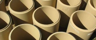
- Thick-walled metal pipe.
- Fiberglass.
- Metal channels.
- Asbestos.
- Chisel.
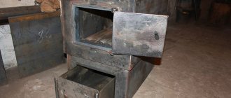
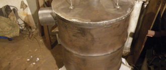
The function of the body of the heating unit in question will be performed by a large metal barrel. You can use either new or old container. The main thing is that the barrel does not have through holes and signs of severe corrosion damage.
The function of the body of the heating unit in question will be performed by a large metal barrel
If possible, it is best to use a Soviet-made barrel. Such products are much more durable and high quality compared to their modern counterparts.
If you have access to a rolling machine, you can purchase a large sheet of metal and use it to assemble the boiler body. The recommended sheet thickness is 2.5-3 mm. The optimal dimensions are 125*250 cm. At the end you should get 2 cylinders with a diameter of 50 and 45 cm.
Furnace assembly
The work of making a sling boiler is carried out in a few simple steps.
First step. Clean the barrel from all sorts of contaminants, and then cut a hole in its top. That is, you simply need to “knock out” the top of the container to gain free access to its interior.
Sheet metal housing
Second step. Cut a small piece from a metal pipe with a diameter of about 15 cm. From it you will make a pipe for connecting the chimney.
Third step. Cut a hole in the side wall of the barrel to install the previously prepared pipe, and then weld a section of the smoke exhaust pipe to the finished hole.
Hatch for cleaning ash
Fourth step. Take the previously cut top of the barrel and make a hole in it with a diameter of about 100 mm.
Double fuel loading hatch with asbestos gasket
Fifth step. Prepare a pipe with a diameter of 10 cm and weld it to the hole prepared in the previous step. The length of the pipe should slightly exceed the height of the barrel.
Double wall boiler with asbestos lining
The holes in the inner cylinder are pre-cut
The external hole was cut and the exhaust pipe was welded in
Sixth step. Take 4 metal channels and weld them along the radius of the boiler lid. You need to weld at every 45 degrees of the circle.
A pancake with an air supply pipe was made
A pancake with an air supply pipe was made
Seventh step. Weld a pre-prepared pipe to the back of the cover. Place the lid on the barrel.
Eighth step. Make a damper for the blower pipe. By changing the position of this damper, you can set the desired intensity of traction.
Requirements for connecting the boiler to the heating system
GENERAL INFORMATION
The boiler must be installed by qualified specialists who provide guarantees for their work.
When installing additional elements, please read the manufacturers' requirements and follow them:
Following the recommendations of the thermal valve manufacturers, install the pre-flow control valves in accordance with the heating system design instructions.
Do not exceed the temperature of the flow into the heated floor using automatic floor heating elements (strictly follow the recommendations of the heated floor manufacturer, as a rule, the temperature recommended by the manufacturer is 28–35 °C).
To avoid bypassing the boiler and heating elements, install three-way or four-way valves and a circular pump in a large ring of the home heating system. Preferably on the return flow pipe.
Do not bypass the boiler and heating elements using a parallel connected boiler to the boiler (if the boiler is connected in parallel, be sure to use a balancing valve).
Maintain sufficient temperature for good boiler operation (65–85 °C). It is not allowed to install a damper to close the chimney. To reduce its traction, use a standard clamp. Make sure there is sufficient ventilation in the boiler room.
Every time you install a boiler, review the technical data sheet (useful additions or recommendations are possible).
For the correct operation and installation of Stropuva solid fuel boilers, regardless of the rated power, it is necessary to comply with the technical conditions:
To regulate the coolant flow passing through the boiler and simplify the boiler settings, it is necessary to install a balance valve with a flow meter before connecting the return circuit to the boiler. We recommend using balancing valve SRV-IG DN 25, BP 1″ Watts.
After setting on the valve passing through the technical. flow condition, when setting up the boiler, you only need to set the coolant supply temperature using the support bolt (2) on the bithermal draft regulator.
To light the boiler, as well as to increase the temperature of the return flow of coolant, it is necessary to mix the return flow with the supply coolant using a flow mixing unit (mechanical three-way valve, thermostatic three-way valve or hydraulic separator).
Stropuva pellet boilers
Stropuva solid fuel pellet boilers can operate in two modes.
- Designed for burning wood in long-term burning mode. At the same time, autonomous combustion from one stack of firewood is ensured for 30 hours, with minimal load.
- The operating mode is associated with the ability to burn with pellets. Burning from one bookmark to 72 hours.
Dual-fuel boilers have almost identical technical characteristics as equipment that runs exclusively on wood.
Pellets are burned using a special burner, which gradually goes down as the pellets burn out. This design of the Stropuva solid fuel pellet boiler allows you to increase efficiency and reduce heat loss. Due to the fact that the coolant circulates around the entire heat exchanger, its rapid and uniform heating is ensured.
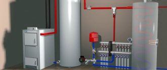
Appearance and specification of the unit with boiler connection, without heated floors
Unit components
- Upper collector. Set: supply pipe connector (15), boiler and heating system disconnect valve (14), automatic air valve (19), pressure gauge (18).
- Vertical collector. The manifold is equipped with a valve (7) to the cooling radiator 4, valves for the boiler supply and return lines (16).
- Mixing unit. Set: three-way mixing valve (10), balancing valve (11), circulation pump (5), heating supply valve (8), return valve (9). The circulation pump is installed with union nuts (17).
- Lower collector. Set: valve for installation of the expansion tank (12), drain make-up valve (13), valve intended for repair and maintenance of the boiler (14), return pipe connector (15).
All parts of the unit for assembly are equipped with connectors (6).
The expansion tank is not included in the standard package of the unit and is selected individually based on the existing heating system.
Types and technical characteristics
At the moment, Stropuva is available in three varieties: wood-burning, pellet and universal. Each of these three varieties is designed for a specific type of fuel, but can work on any other, albeit with less efficiency. In total, the line includes 4 standard sizes: 10, 15, 20, 40 kW and a Mini version with a power of 8 kW.
The Stropuva wood-burning boiler is equipped with a special air distributor, which allows efficient burning of wood, and has the following characteristics:
| Model | Mini S | S10 | S15 | S20 | S40 |
| power, kWt | 8 | 10 | 15 | 20 | 40 |
| Room area, m² | 30-80 | 50-100 | 75-150 | 100-200 | 200-400 |
| Efficiency, % | 86,3 | ||||
| Firewood capacity, dm³ | 120 | 150 | 200 | 230 | 360 |
| Chimney diameter, mm | 160 | 180 | 200 | ||
| Burning duration, h | 31,5 | ||||
| Price, rub | 65 000 | 87 150 | 92 348 | 97 545 | 107 730 |
The pellet version is equipped with a distributor for fuel pellets and an air supply manifold. Boilers operating on pellets have the following data:
| Model | Mini SP | S10P | S15P | S20P | S40P |
| power, kWt | 8 | 10 | 15 | 20 | 40 |
| Room area, m² | 30-80 | 50-100 | 75-150 | 100-200 | 200-400 |
| Efficiency, % | 86,3 | ||||
| Pellet capacity, kg | 50 | 70 | 110 | 120 | 200 |
| Chimney diameter, mm | 160 | 180 | |||
| Burning duration, h | 72 | ||||
| Price, rub | 65 000 | 91 350 | 97 072 | 102 795 | 112 980 |
The last representative of solid fuel boilers is universal. These devices can operate on coal, wood, fuel briquettes and pellets. The delivery set includes distributors for all types of fuel, as well as an air supply manifold. They have the following technical characteristics:
| Model | Mini SP | S10P | S15P | S20P | S40P |
| power, kWt | 8 | 10 | 15 | 20 | 40 |
| Room area, m² | 30-80 | 50-100 | 75-150 | 100-200 | 200-400 |
| Efficiency, % | 86,8 | ||||
| Pellet capacity, kg | 50 | 70 | 110 | 120 | 200 |
| Chimney diameter, mm | 160 | 180 | 200 | ||
| Duration of coal combustion, h | 130 | ||||
| Price, rub | 65 000 | 102 700 | 114 608 | 121 380 | 127 995 |
As you can see, from the presented model range you can choose a solid fuel boiler for any room, type of fuel and available budget.
Schematic diagram of a unit with a boiler connection, without heated floors
Unit components
- Safety valve
- Automatic air vent
- Pressure gauge
- Boiler
- Cooling radiator
- Radiators
- Circulation pump
- Three way mixing valve
- Balancing valve
- Expansion tank
- Boiler
Purpose of boiler lining
The main task of boiler lining is to protect the environment from the effects of flue gases. Additional goals of the same design include:
- reducing heat loss from the unit (and thus increasing its efficiency and reducing fuel costs);
- preventing the intake of outside air into gas ducts in which pressure decreases;
- ingress of flue gases from flues when pressure increases.
The requirements that the lining must meet include the boiler surface temperature. It should be no higher than 45 degrees in those places where it can be touched by operating personnel, and up to 55 degrees in other areas. The value of specific heat losses is within 350 W/m.
In domestic conditions, it is not possible to use a cavitation heat generator to heat a house, since it is too noisy.
Correct installation of polystyrene foam on the facade will significantly reduce heat loss in the room.
Structurally, the lining of boiler equipment includes insulation, metal fastening parts, bricks and sealing compounds (see Boiler room in a cottage: basic elements and design rules). Density and thickness are selected in accordance with the temperature inside the boiler and the intensity of the impact of fuel slag on the furnace. The higher these indicators, the thicker and stronger the lining should be.
Description of the unit with boiler connection, without heated floors
The coolant heated in the boiler passes through steel pipes d 25 mm for boilers. Air is removed from the boiler through an automatic air vent (3). A safety valve (0) of 1.5 atmospheres is installed on the external circuit of the boiler. The coolant is directed along the external circuit through the valve to the hot water boiler (3). After heating the boiler, the coolant flows back into the outer circuit of the piping unit.
After the boiler (3), a selection is made to an additional radiator, which, in the event of a power failure, can operate as a gravity radiator. The additional radiator (2) must be connected independently. It is necessary to prevent overheating of the boiler when the circulation pump is turned off.
The radiator system (1) is connected at the top of the small circuit through a valve d 25 mm. The return line of the radiators is supplied to the circulation pump through a valve d 25 mm. The heated coolant from the boiler enters the heating system manifold and then into the radiator system (1).
The cooled coolant flows from the return manifold to the circulation pump (5).
The balancing valve (8) regulates the flow of coolant passing through it so that there is enough coolant to heat the radiators, and at the same time, so that it is sufficient for the boiler itself. The total volume of coolant flow through the balancing valve depends on the power of the circulation pump and on the selected heating system design.
The flow rate through the balancing valve should be within 16 l/min. The three-way mixing valve (6) is connected to the circulation pump (5) and to the common return line. A three-way mixing valve (6) is necessary to mix the coolant in the return and supply lines and regulate the temperature of the boiler in order to prevent the formation of condensation.
In the return line after the balancing valve, drain valves are installed to recharge and drain the system, as well as an expansion tank (9).
The pressure in the expansion tank should be 0.5–0.7 atmospheres.
If necessary, an electric boiler can be installed instead of a boiler.
Types of schemes
Today there are several strapping schemes. It is possible to talk about which piping of solid fuel boilers is better or more efficient only after a detailed analysis of the heating design features. For example, the simplest scheme is to connect the boiler to a gravity system. This scheme is quite simple, but it provides not only a high level of efficiency, but also the most important thing in the work - safety.
Connecting the boiler to the gravity system
With such a scheme, it is mandatory to have an open or membrane type expansion tank in the scheme. In the first case, the location of the tank plays a huge role, and in the second, the presence of a safety valve.
The piping of solid fuel boilers according to this scheme is very simple, but poorly controlled. Constant monitoring of fuel and its high consumption require improved design.
The circuit can be “outwitted” if a three-way thermal valve is inserted into the system. In this case, the set coolant temperature will be maintained by mixing water from the return to the supply. A design solution with a pump, thermoelement or when using low-power solid fuel boilers is possible.
The valve is installed on the return flow of the coolant and when the temperature of the coolant rises above normal, the automation will block access to mixing.
An important point is the pump in the system. Since it operates from the network, you should monitor its availability. For example, a heat accumulator solves the problem of sudden pump shutdown.
The wiring diagram for a solid fuel boiler can be presented in different designs, but some features are common.
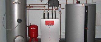
Appearance and specification of the unit with connection of the boiler and heated floors
Unit components
- Upper collector. Set: supply pipe connector (15), boiler and heating system disconnect valve (14), automatic air valve (19), pressure gauge (18).
- Vertical collector. The manifold is equipped with a valve (7) to the cooling radiator (4, see schematic diagram), and valves for the boiler supply and return lines (16).
- Mixing unit. Set: three-way mixing valve (10), balancing valve (11), circulation pump (5), heating system supply valve (8), return line valve (9), underfloor heating return line valve (16). The circulation pump is installed with union nuts (17).
- Lower collector. Set: valve for installation of the expansion tank (12), drain make-up valve (13), valve intended for repair and maintenance of the boiler (14), return pipe connector (15).
All parts of the unit for assembly are equipped with connectors (6).
The expansion tank is not included in the standard package of the unit and is selected individually based on the existing heating system.
Types of equipment Stropuva
Stropuva heating devices operate on one or more types of fuel, depending on the model.
Wood-burning
A wood boiler uses hardwood logs, wood and peat briquettes as fuel.
Pellet
The pellet device obtains thermal energy by burning fuel pellets consisting of wood and agricultural waste. It is equipped with an air charge fan, a grate and a specially designed air distributor.
Universal
Universal models, in addition to firewood and pellets, also use coal and anthracite. It is equipped with special parts for working with bulk raw materials.
Schematic diagram of the unit with connection of the boiler and heated floors
- Safety valve
- Automatic air vent
- Pressure gauge
- Radiator
- Boiler
- Cooling radiator
- Warm floor
- Heated floor circulation pump
- Three way dividing valve
- Heated floor circulation pump
- Three way dividing valve
- Circulation pump
- Three way mixing valve
- Balancing valve
- Expansion tank
- Boiler