Content
- Normative base
- Types of hot water boilers using solid fuels
- Connection diagrams for solid fuel boilers
- Open circuit with natural circulation
- Combined circuit with expansion tank and circulation pump
- Closed circuit with forced circulation
- Scheme with artificial circulation and hydraulic separator
- Results
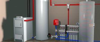
Solid fuel water heating boilers of low and medium power are designed for heating residential, public and industrial premises. They generate heat by burning solid fuel: firewood, briquetted sawdust or peat. The main advantages of such units are versatility of use, autonomous operation (no connection to gas supply networks is required), and affordable fuel. Modern heating devices are economical, safe and easy to operate, but you need to know how to properly connect a solid fuel boiler to the heating system.
DIY pyrolysis boiler
To make a pyrolysis solid fuel heating system , an amateur craftsman will first have to study the available information on this issue.
Within the framework of our article, we are able to give only general recommendations, and detailed drawings can be searched on the Internet. It is also useful to look at forums where experts exchange opinions.
According to their reviews, making pyrolysis heating boilers with your own hands will still cost less than buying branded ones.
The power of a pyrolysis boiler is determined by several factors, and the main ones are: the overall dimensions of the product, the volume of the combustion chamber and the height of the primary air supply.
Any ready-made heating system diagram with a pyrolysis boiler will need to be modified taking into account the specific conditions of your home.
Materials and manufacturing technology
To make a pyrolysis heating boiler with your own hands you will need:
- electric welding machine and a good supply of electrodes;
- “grinder” and at least 20 cutting wheels;
- steel 4mm, 3 sheets 1.25×2.5 m;
- steel 2 mm, one sheet;
- pipe 57 mm with a total length of 8 m;
- fireclay brick, 12-14 pcs.;
- and some other small details.
Cutting metal and performing welding work is not an easy task. If it is not possible to do this yourself, you will have to invite a specialist.
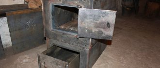
The boiler doors must be closed hermetically to prevent heat loss and smoke escape.
Testing the finished boiler
During the test, the shortcomings of a homemade heating boiler should be identified and ways to eliminate them should be determined. A well-installed pyrolysis unit has the following properties:
- fuel flares up quite easily with natural draft;
- smoke does not escape from under the top door seal;
- the fan provides a stable air flow and is not noisy;
- the boiler reaches operating mode in 20-30 minutes;
- when the fan is turned on, the flame in the combustion chamber is strong and even;
- the combustion process of pyrolysis gas can be regulated;
- when the fan stops, there is no backdraft effect;
- the ratio of thermal power to the amount of firewood consumed corresponds to calculations.
If a home-made heating boiler demonstrates compliance with these parameters, it can be considered operational after eliminating the detected deficiencies.
Normative base
A heating boiler operating on solid fuel is subject to increased safety requirements. Equipment installation standards are given in SNiP II-35-76 Boiler installations (current edition SP 89.13330.2011).
According to the standard, hot water solid fuel boilers for public, administrative and residential buildings with a water heating temperature at the outlet of up to 115 °C can be placed in built-in and attached boiler rooms (placement on the roof is not allowed). In multi-apartment residential buildings they can only be installed in attached premises. Heating equipment must be factory-made, with built-in automation.
The maximum total thermal power of solid fuel boilers for a built-in boiler room should not exceed 1.5 MW. For an attached room this figure is not limited.
Requirements for the design of a chimney for the removal of combustion products, the installation of ventilation and water heating are regulated by the standard SP 31-106-2002 Design and construction of engineering systems of single-apartment residential buildings. It also stipulates the conditions for correct installation of the device (distance from the walls, boiler room finishing material), they must be taken into account together with the boiler operating manual.
Principle of operation
It is impossible to evaluate the advantages of pyrolysis boilers without understanding the general principles of operation. And initially, what is pyrolysis?
Essentially, this is the decomposition of natural compounds with a minimum amount of air. In a standard boiler, firewood burns at a temperature of 900-1200°C with normal air access; one load of firewood takes about 3-4 hours, releasing about 4900 calories of heat.
Table 1 Calorific value of firewood of different types of wood
In a pyrolysis boiler, solid fuel burns at a lower temperature - 300–850 ° C, and decomposes into the following elements - solid sediment and gas. In the absence of oxygen in a separate chamber, flammable (pyrolysis gas) reacts with carbon and is further processed, thereby increasing thermal conductivity.
Thus, during dry distillation (pyrolysis process), in addition to solid fuel, solid sediment is additionally burned and, at the same time, pyrolysis gas. All this together increases the burning time of one load of firewood to 12 hours (compare with the usual 3-4 hours) and the efficiency of the boiler to 85-90% with the standard 65-70%.
Pros and cons of equipment
Any unit has both positive and negative characteristics. In order to make the right choice, they must be adequately assessed.
- maintaining a certain combustion temperature in automatic mode;
- increased burning time of the fill against the background of increased boiler efficiency;
- the ability to use various types of solid fuel, including processed products from the woodworking and agricultural industries.
It is not recommended to use more than a third of the total amount of fuel polymers and rubber.
- large dimensions of the boiler due to the enlarged combustion chamber;
- special requirements for solid fuel - firewood must be completely dry
When fuel is added to even 25% humidity, the process of gas evolution slows down, which leads to a decrease in coolant temperature and a drop in efficiency.
- energy dependence - during operation, the boiler consumes electricity to operate the fan, which creates forced draft, and automation;
- price is the main drawback that makes you refuse to buy.
That is why we propose to make a pyrolysis boiler with your own hands; see the drawings and principle of operation further in the article.
Boiler structure
The fundamental difference between a standard and a pyrolysis boiler is that in the first version there is 1 combustion chamber, and in the second - 2, between which there is a grate, the fuel itself and the solid residue are burned in the lower one, and pyrolysis gases in the upper one. It is this organization of combustion chambers that allows you to optimize the process, increase fuel combustion time and maximize efficiency.
Photo 2 Diagram of the pyrolysis boiler
The pyrolysis process is possible only with limited air access, when the fuel does not burn, but actually smolderes, releasing a larger amount of gas.
Among the features of a pyrolysis boiler is increased aerodynamic resistance in the chimney due to the absence of air and the reaction of carbon with pyrolysis gas. Forced draft is provided by an electric fan; in fact, it is for this reason that pyrolysis boilers belong to the category of volatile equipment.
Cost of a homemade model
Of course, the main reason why they start making a pyrolysis boiler with their own hands, looking for drawings and the operating principle is banal savings. On average across regions, the cost of a finished boiler varies from 36,000 rubles. (power 10 kW, area 100 sq.m.) up to 140,000 rub. (power 38 kW, area 300 sq.m.). When making a boiler yourself, you can save from 500 to 1500 USD. due to the cost of materials and personal labor.
Video 1 Pyrolysis boiler 15-25 kW - manufacturing and testing
In any case, this type of work cannot be called inexpensive or easy, so before you decide to make a pyrolysis boiler with your own hands, evaluate your capabilities, study all the drawings and select exactly the materials that are needed.
How to make a pyrolysis boiler
- electric arc welding and 3-4 electrode packages;
- drill;
- small grinder (circle 230).
Of all types of heating installations operating on solid fuel, the most effective are those in which pyrolysis occurs when burning wood or coal. This is the process of afterburning gases released from firewood or coal during their smoldering, which allows almost all the energy of fuel combustion to be transferred to the coolant. This principle uses a pyrolysis boiler circuit, in which the separation of combustible gas from fuel and its subsequent combustion is realized.
Types of hot water boilers using solid fuels
To connect a solid fuel boiler, you need to understand the principle of its operation. The heat released during combustion is transferred to water, which circulates in the cavities of the boiler furnace and convective heating surfaces at the flue gas outlet. Hot water leaves the boiler and enters the supply pipe of the circulation heating circuit. The coolant then flows to the heating radiators, where it gives off heat to the air in the rooms, and returns through the return pipeline to the boiler. Based on the combustion method, the following types of heating devices are distinguished:
- Conventional solid fuel boilers with bottom combustion air supply.
- Long-burning boilers (with top air supply) are gas generators with afterburning of pyrolysis gas released during the combustion of the main fuel.
Boilers are also divided into domestic (for country houses or private houses) and industrial (for large public premises). The equipment varies in size and volume of the furnace, duration of fuel burning, heat output, and water volume in the system.
Calculation of a pyrolysis boiler
The calculation begins with determining the temperature difference, ºС:
Ƭ= (∆T - ∆t) / ln (∆T / ∆t)
- ∆Т – temperature difference of combustion products before and after the heat exchanger;
- ∆t is the difference between the temperatures in the coolant supply and return pipelines.
The resulting value Ƭ is substituted into the formula:
S = Q / k / Ƭ , where:
- Q – design power of the heating installation, W;
- k – heat transfer coefficient, equal to 30 W / m 2 ºС.
An enlarged calculation of the power of a pyrolysis boiler (Q, kW) is performed based on the area of the building. Its value must be taken according to the external measurement of the house, the result divided by 10. The meaning of this action is that approximately 10 kW of thermal energy is required to heat every 100 m 2 of the building. The result obtained is the calculated power of the heating system, and the heat source is taken with a safety factor. It depends on the region of residence and ranges from 1.1 to 1.5.
Connection diagrams for solid fuel boilers
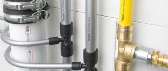
Long-burning solid fuel boilers are universal equipment that can operate with both open and closed circulation circuits. Let's consider the most popular connection options using the example of the thermal diagram of the Suvorov-M household heating unit.
Open circuit with natural circulation
With natural circulation, the movement of water in the thermal circuit occurs due to the expansion and contraction of the coolant as it heats up/cools. An increase in water volume leads to the creation of excess pressure without the use of injection pumps. The gravity flow circuit necessarily contains an atmospheric expansion tank filled with liquid.
Figure 1 Open circuit with natural circulation
The scheme works as follows. The water heated in the boiler (1) enters the supply pipeline, which rises vertically and is then distributed overhead throughout the heated rooms. The supply pipeline is laid at a slight angle to ensure spontaneous drainage of the coolant. From the pressure network, water descends to the radiators, gives off heat and returns to the boiler through the return pipeline, which is also laid downhill.
An expansion tank (5) is installed at the top point of the system and is connected to the pressure pipeline. Excess coolant enters the expansion tank when it overheats - for example, if the water in the pipes boils. Make-up water can be filled through the expansion tank; a tap (6) is provided for this. There is also an overflow valve installed here to drain excess water.
The expansion tank acts as a water seal and dampens hydraulic vibrations of the system. It also cuts off the water circuit from the atmosphere and prevents it from becoming airy.
To control the parameters of the coolant, thermometers are connected at the inlet/outlet of the boiler: at the supply (4) and at the return (9). Also installed on the return pipeline is a shut-off valve (8), which disconnects the boiler from the heating network, and a drain (7) for draining water.
The natural circulation scheme has certain advantages:
- reliability of operation - there is nothing to break here;
- ease of system maintenance;
- lack of expensive equipment;
- independence from the availability of electricity.
But there are also quite serious disadvantages. Due to the low water pressure, in order to overcome the hydraulic resistance of the system, it is necessary to significantly increase the diameters of the pipelines, which significantly increases the cost of the design. Also, if additional pressure losses occur (for example, when installing additional radiators or reducing the useful cross-section of pipelines due to scale deposits), circulation disturbances are possible, which leads to overheating of the heating surfaces in the furnace. Now gravity-fed open systems are practically not used.
Combined circuit with expansion tank and circulation pump
With this option, the classic open circuit is complemented by a circulation pump. It builds up pressure in network pipelines, eliminating disruption of coolant circulation along the thermal circuit.
Figure 2 Combined circuit
The scheme is in many ways similar to the previous one. Additionally, there is a unit with a circulation pump (16), it is installed on the bypass on the return. A filter (16) is provided in front of the pump to purify water from mechanical impurities (rust, sand, debris). Valves (14) are installed on the bypass pipeline to allow removal of the pump and filter. A bypass valve (13) is also installed on the main return pipeline to switch the flow direction.
In addition, install a valve on the supply (6), after connecting the expansion tank (7) and cut a pipe with an air valve (11) into the supply pipeline to bleed air from the system. To control the pressure in the supply network, a pressure gauge (8) is installed.
With such a scheme, it is quite difficult to select the operating pressure at the outlet of the pump. Here it is necessary, on the one hand, to ensure reliable circulation, and on the other hand, to prevent excessive overflow of water through the expansion tank. In practice, this is almost impossible.
Closed circuit with forced circulation
In such a system, coolant circulation is carried out due to the operation of the pump. It creates an excess pressure of the order of 0.06-0.2 MPa (0.6-2.0 bar). There is also a tank here, but it is of a membrane type and is not connected to the atmosphere.
Figure 2 Closed circuit with forced circulation
Principle of operation. The heated coolant flows from the boiler into the supply pipeline, its temperature is controlled using a thermometer (4). On the supply side, a safety group (7) is installed at the top point, which includes a relief valve, a pressure gauge and a valve. The safety group is activated if the coolant pressure exceeds the permissible value. Also, a supply shut-off valve (8) and a drain valve (15) are installed on the supply line to bleed air trapped in the system.
Due to the excess water pressure in closed circuits, the supply does not have to be laid under the ceiling. Therefore, all heating pipes can be laid hidden in the floor.
The supply pipe distributes water throughout the heating system. After heat transfer, the coolant is conveyed to the boiler via the return line. The following are installed in series on the return pipeline: high-pressure expansion tank (14); bypass line with filter (10), pump (9) and bypass valves (13, 11); bypass valve (12); return thermometer (6); shut-off valve on the return pipeline (5). Between the shut-off valve and the boiler, a make-up pipeline with shut-off valves (8) is cut into the return line. There is also provision for draining water through a drain valve (9) for periodic inspection.
The advantages of a closed scheme include:
- stable operation without the risk of circulation disruption;
- small diameters of network pipelines;
- economical due to the small volume of water in the system;
- absence of a massive atmospheric tank;
- Possibility of laying all pipes at the bottom.
Among the disadvantages are energy dependence (in the absence of light, the pumps do not work), the need for periodic inspection of the filter and pump, the presence of additional equipment - a pump, a safety group, a membrane expander. But all these disadvantages are offset by the advantages of the scheme.
Scheme with artificial circulation and hydraulic separator
This system is a modified, improved version of the previous scheme. It provides an additional mounting unit - a hydraulic separator. With its help, a small circuit is created connecting the inlet and outlet of the boiler.
Circulation through the small circuit is carried out during the startup period of the boiler, until the supply water is heated to operating levels. After reaching the specified modes, part of the hot water will begin to flow into the heating system.
Mixing hot water from the supply to the return does not allow the temperature of the return coolant to drop below 40 °C. This eliminates the risk of condensation appearing in the furnace, which affects the technical characteristics of the unit and increases the adhesion of ash to the pipe screens.
Figure 3 Scheme with artificial circulation and hydraulic separator
The hydraulic separator can be made in the form of a large-diameter pipe into which the inlet and outlet of the supply and return pipelines are embedded. A more modern and convenient design of the separator is a jumper with a three-way valve installed at the return connection point.
Manufacturing of a pyrolysis boiler
The efficiency of this type of wood-burning installations has become the reason for their popularity among craftsmen who can make solid fuel pyrolysis boilers on their own from available materials. This process is quite labor-intensive and requires skills in plumbing and welding, a certain minimum of tools and equipment:
- electric welding machine;
- angle grinder;
- electric drill;
- set of locksmith tools.
If you have the skills, tools and a great desire, you can make a unit using the following drawing of a natural draft pyrolysis boiler:
1 – air channel; 2 – door for loading fuel; 3 – secondary chamber door; 4 – direct draft damper; 5 – primary chamber; 6 – top cover; 7 – inlet channel for air supply; 8 – air damper; 9 – pipe for the safety group; 10 – secondary afterburning chamber; 11 – chimney connection pipe; 12 – nozzle; 13 – fire tube heat exchanger.
The material for making the chambers can be heat-resistant alloy steel, but this is an expensive material, so craftsmen take simple carbon steel 5 mm thick. To protect it from high temperatures, the pyrolysis boiler is lined with refractory bricks in the lower part of the furnace. They also need to protect the bottom of the secondary chamber, where the flame is directed. To cover the water jacket, sheet metal 3 mm thick is used, it is welded to the stiffeners made of strip steel. The doors, lids and frames of the openings are made from the same metal.
The boiler device provides heat transfer from flue gases through a fire tube heat exchanger located inside the water jacket. For its manufacture, seamless steel pipes made of carbon steel with an outer diameter of 48 or 57 mm are suitable. The number of pipes should be selected according to the required heat exchange surface area, for which the pyrolysis boiler is calculated.
Considering that the fuel in pyrolysis units burns for a long time (up to 12 hours) and is productive, some owners of classic direct combustion units are wondering whether they can be modernized. Such a conversion of a solid fuel boiler into a pyrolysis boiler is possible, but provided that the furnace of the unit is made of metal and not cast iron. The grate is removed and, using electric welding, a partition is fixed in its place, separating the main firebox and the ash pan, which will serve as a secondary chamber. A nozzle is installed between them. In addition, you will need to organize an air supply to both chambers; you need to make air channels and install them, as shown in the drawing.
As a rule, converting a boiler into a pyrolysis boiler occurs not on factory units, but on home-made ones, this expands the possibilities for improving the design. You can change the nozzle flow area, the dimensions of both chambers or the surface heat exchange area, achieving the best combustion duration and increasing the efficiency of the installation.
Results
You can install the heating system of a hot water boiler yourself. But for this you need to correctly select and calculate its parameters. Initially, a connection diagram for a solid fuel boiler is selected that is optimal for a particular facility. Then you need to select radiators, calculate the hydraulic resistance of the network, determine the diameters of the network pipelines, calculate the volume of water in the system, and select the power of the equipment. To avoid annoying mistakes, it is better to entrust this work to specialists - the calculation of the heating system is carried out at the design stage in terms of air conditioning.
Requirements for homemade pyrolysis boilers
In order for a home-made pyrolysis heating boiler to surpass the efficiency of a conventional solid fuel boiler, its design must meet strict requirements:
- the temperature in the furnace should be optimal (600–700 °C), since it is under these conditions that the highest quality release of pyrolysis products occurs;
- regulation of combustion power should not significantly reduce efficiency;
- the heating boiler must be suitable for long-term continuous combustion of fuel;
- the body of the pyrolysis gas combustion chamber must be resistant to corrosion and able to withstand temperatures above 1200 °C.
It is also desirable that the boiler design include a chamber for pre-drying wood raw materials.
Technical characteristics that a homemade pyrolysis boiler should have for heating a private home:
| Technical specifications |
Using a homemade heating device can sometimes be risky, because if the combustion process is not adjusted correctly, a so-called “pop” can occur—an explosion of pyrolysis gas.
Operating principle
Before considering the diagrams and drawings of pyrolysis boilers, it is necessary to understand the principle of their operation. So, in the process of burning fuel (in other words - dry distillation) under the influence of high temperatures (about 200-800 ° C) and insufficient oxygen, wood decomposes into two parts: the volatile part (pyrolysis gas) and solid sediment ( charcoal).
The design of the pyrolysis boiler assumes that pyrolysis gas will accumulate at the top of the chamber, which, with the air flow created by the smoke exhauster, will be sent for afterburning to another chamber. This is an exoteric process, accompanied by the release of heat, which improves heating, dries the fuel in the boiler, and also heats the air entering the combustion zone. The mixing of pyrolysis gas released at high temperature with atmospheric oxygen causes the combustion process of the former, which is subsequently used to produce thermal energy.
Essential elements
For example, let’s take the finished circuit of a Belyaev boiler with a power of 40 kW. It contains the following main elements:
- Controller for the boiler circuit.
- Door designed for loading fuel.
- Ash pan lid.
- Smoke exhauster.
- Coupling for temperature fuse sensor.
- Emergency line connection.
- Supply line.
- Cold water supply to the protective heat exchanger.
- Supply of hot water to the protective heat exchanger.
- Return line.
- Emptying pipe and expansion tank.
Of course, with experience and some engineering knowledge, you can easily change the design of the boiler. The connection diagram for the pyrolysis boiler can be modified at your discretion. However, work must be performed in such a way as not to violate the dimensions of the internal chamber.