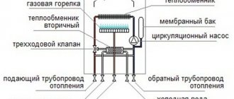
Full technical description of gas valve Eurosit 630
Full technical description of gas valve Eurosit 630
Today, this is the most common gas valve installed on non-volatile gas boilers of Russian and foreign production. Below we provide you with detailed information on this device, which, in our opinion, can be very useful not only for professionals. Information provided by SIT Group.
If you are interested in directly diagnosing the malfunction of AOGV boilers with imported units, we bring to your attention "Faults of AOGV with a Honeywell or Eurosi unit"
So. What is Eurosit 630, essentially? This is a multifunctional gas supply regulator with a modulating thermostat and the function of full modulating activation of the main burner. Eurosit 630 is a non-volatile device, which makes it unique for solving problems of any kind, say, operating a boiler from a gas holder or from liquefied gas cylinders, without the use of electricity sources. The valve is available in various designs and is used without any additional complications in gas convectors, gas boilers, grills and other wide variety of gas-consuming equipment that requires precise temperature control.
Basic technical capabilities
In parentheses we give a function designation that will help in understanding the two working schemes below.
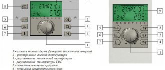
1. Control knob with positions “off”, “ignition”, “temperature”. (MS) 2. Thermoelectric flame protection system (we are talking about a thermocouple) with blocking the gas supply to the main burner after switching off (the blocking is available after switching off the boiler, i.e. it means protection from unauthorized activation, for example children). (GM) 3. Maximum gas flow adjustment device (RQ) or, optionally, a pressure regulator. (PR) 4. Minimum gas flow adjustment screw. (by pass) 5. Modulation thermostat with the function of completely turning off the main burner. (TH) 6. Gas outlet to the pilot burner with a gas flow adjustment screw. (RQ) 7. Inlet filter and pilot burner filter. (FL) 8. Connections for measuring gas pressure. 9. Gas supply, optionally, from the side or from below. 10. Options for gas connections of the multifunction regulator: pipe with external thread or pipe connection using a nut with a seal.
Two variants of operating schemes (with and without pressure regulator)
Technical data of the Eurosit 630 valve (EN 126 standard)
For reference. The EN 126 standard applies to control devices with two or more functions, one of which is gas shut-off.
Connections 1/2 ISO 7 Operating position - any Gas used (families) - 1,2 and 3 Maximum gas input pressure - 50 mbar Regulator setting range from 3 to 18 mbar Operating ambient temperature from 0 to 80C Pressure regulator (optional) - Class. C Torsional and bending stability - Group 2 Thermoelectric protection system (using SIT thermocouples) Ignition time less than 10 sec. Reset time less than 60 sec. Rated glass of ignition cycles - 10,000 Manual reset system: estimated number of reset cycles - 10,000
Characteristics
The characteristics of the thermostat with the function of completely turning off the main burner are shown in the following table and graph:
Gas consumption
EXPLOITATION
Ignition of the pilot burner
Make sure the control knob is in the "off" position, turn the control knob to the "spark" position. Press the control knob and light the pilot while holding the control knob for a few seconds. (Fig. 1)
Release the control knob and check that the pilot burner is lit (Fig. 2). If the pilot burner goes out, repeat the ignition procedure. If all other attempts to start the pilot burner have not resulted, either the gas control thermocouple is faulty, or the circuit between the “poor draft” thermal relay and the breaker is broken.
Temperature selection
Turn the control knob to the position corresponding to the selected temperature (Fig. 3)
Duty position
When turning the control knob from the selected temperature position to the “spark” position, the main burner goes out, but the pilot burner remains lit. That is, in essence, this position puts the boiler on, like “a car idling.” Is the boiler working? Yes. Is it warm? No.
IMPORTANT! This mode allows you to cool the boiler when there is a necessary sharp change in the operating temperature of the boiler from higher to lower. Otherwise, without cooling the boiler in this way, you can easily “crush” the modulation thermostat cylinder (in Russian, bellows-thermocylinder assembly (like the Zhukovsky boiler)
Turning off the boiler
Turn the control knob to the "Off" position. (Fig. 4)
ATTENTION! Restarting the device after an unexpected emergency shutdown can be done approximately a minute after the boiler is turned off. Because turning the knob to the “pilot” position is possible only after the flame control thermocouple has cooled. (i.e. the handle should bounce up rather than remain pressed down). While the thermocouple produces thermoEMF, the thermoelectric flame control device is in the blocking position.
Installation
The gas valve Eurosit 630 complies with current safety standards. Installation on gas consuming equipment must be carried out in accordance with the specific requirements that exist for this equipment.
Firstly , compliance with the requirements regarding thermoelectric protection must be checked. Now we will explain what we are talking about here. Those who have ever seen, this is especially widespread in cases with Economy automation units on domestic gas boilers, where the solenoid valve button, which “bounces” all the time, is tied with tape or secured in a pressed position with whatever you like so that the boiler works. The malfunction here is 90% obvious - the thermocouple is faulty or has poor contact with the solenoid valve. The thermocouple replacement procedure usually takes 2-3 minutes. But for some reason, no. The button is attached, and when the igniter goes out for any reason (and there are any number of them), the flow of gas into the house is always open, as they say, wide open. Secondly. Compliance with gas pressure requirements. Here we are talking about the presence of a pressure reducer. This applies, you understand, to the operation of the valve on liquefied gas, be it a gas tank or cylinders. At first glance, the requirement is simple, but practice sometimes shows something completely different. Moreover, we are talking here not so much about Eurosit 630 gas valves, but about gas valves, for example, Sigma 845.
A small but useful digression
When the specified pressure requirement is not met, do you know what happens? The Sigma 845 gas valve is installed on a huge number of wall-mounted and floor-standing gas boilers. Moreover, the boilers are not cheap, serious, volatile, with control boards, electric ignition, etc. What we have? Usually this is what. The guys came to do the heating. Done. Does the work need to be submitted? Necessary. Boiler, for example, BAXI floor-standing. There is a gas tank, there is a reducer at the output. They twist and turn, but no one understands what the pressure gauge shows at the outlet. It seems like it should be 2750 Pa or about 300 mm water column, but there the scale is three orders of magnitude coarser than necessary. You can't see anything on this one. The boiler either gives a “no gas” error or does not start at all. Or it will work for half an hour, and then that’s it. Who is to blame when there is no gas? Of course, the gas valve! In the end, do you know what they do? They remove the valve from a completely new boiler and start blowing into it from all sides. It's sulking from here, it's not sulking there. The result is complete panic! Buying the most common one with a factory setting of 300 mbar, to the great amazement of everyone, turns out to solve the problem. It is clear that this requirement also applies to Eurosit 630. But it is non-volatile, there is no board, it will not give us any errors, but it will affect the consumption. And the pilot flame. When you see a column of flame 15 centimeters high FROM THE IGNITER, you will understand what we are talking about. It is very important to carefully understand the gas pressure requirement. Now let's move on to the mechanics.
Mechanical connections
General recommendations
Never damage sealing parts! Never loosen the assembly screws! Avoid shocks, falls, hitting the valve, etc. And further. Never remove the labels on the valve! The information that is indicated there is very important for you and me, because what if we find a replacement later? The valves, of course, have differences, but more on that later. This will come next. Remove dust protection caps only during installation. Make sure gas flow is in the direction indicated by the arrow on the regulator body. Take care to ensure that foreign materials do not enter the valve during installation. Packing foam especially likes to get into all the holes. It just sticks to everything! The plant indicates that some versions of Eurosit 630 may be supplied without certain parts. This note, of course, was primarily written for ourselves, but it won’t hurt you to know it either.
So, together we check the availability of the following components according to Fig. A: - minimum gas flow adjustment screw - 3 - maximum gas flow adjustment screw (sometimes called) - 2 If there are no screws, insert the screws into the corresponding holes 14 and 15.
Gas connection
1. Use 3/8" threaded pipe. It is also possible to connect a D12 mm tube using an O-ring and nut. 2. The valve has two holes in the inlet channels 10 and 12 and two holes in the outlet channels 11 and 13. The holes that we are not using must be closed with plugs.
Igniter connection
This is pin 8. A standard igniter with a diameter of D1/4" is usually screwed into this hole. This is the usual standard configuration. But it is also possible to insert tubes with a diameter of D4 mm, D6 mm with cone seals and corresponding nuts. At the end of the work, be sure to check all connections for leaks.
Installation and adjustment parameters. Complete list for professionals
1. Check the inlet and outlet pressure using gas pressure measuring fittings 6 and 7. After measuring the pressure, carefully plug the fittings. 2. Setting the maximum and minimum gas flow is carried out only with a cold thermal cylinder. 3. Setting the maximum gas flow (version without pressure regulator) Fig. A Turn knob 4 to position 7. Fully tighten adjustment screw 2, and then gradually turn it out until the required gas flow is achieved. ATTENTION! Once fully tightened, do not remove the screw more than two full turns. 4. Disabling the maximum gas flow function. Fully tighten adjustment screw 2, and then turn it out two turns and lock it. Disabling can also be done by replacing adjustment screw 2 with a plug. In this case, the plug must be completely screwed in. 5. Setting the maximum gas flow (version with pressure regulator) Fig. A. Turn the control knob to position 7. When turning adjustment screw 2 clockwise, the gas flow increases. 6. Disabling the pressure regulator function. Turn adjustment screw 2 fully clockwise. 7. Setting the minimum gas flow. Slowly turn the control knob clockwise to the minimum power position (as close as possible to the main burner start position). When turning adjustment screw 3 counterclockwise, the gas flow increases. 8. Setting the gas supply to the igniter. When screw 5 is turned clockwise, gas consumption decreases. 9. Disabling the function of setting the gas supply to the igniter. Fully tighten adjustment screw 5, and then turn it out two turns and lock it. 10. Changing the type of gas. Set the gas pressure at the outlet of the reducer or use a ready-made reducer with a factory setting. We remember that flame separation or breakthrough is strictly prohibited at the maximum and minimum gas pressure, respectively.
Repair of gas valve Eurosit 630
The manufacturer allows only one type of repair work - replacement of the magnetic block. This usually happens when the thermocouple is fully operational and the entire circuit from the thermal relay to the breaker is also operational. All other work, and especially work of the “Kulibin + 0.5 ppm” or “who knows what” class, is strictly prohibited.
Now about the difference between Eurosit 630 blocks. How do they usually differ from each other?
The blocks differ mainly only in the range of temperature control. Standard operating mode for gas boilers is from 40C-90C. Although, on boilers with a power of 11.6 kW there were valves with a temperature range from 40C to 72C. This does not affect the operation of the boilers in any way, therefore, valve 0630068, which supports the range 40C-90C, practically solves any problem.
To quickly assess the situation, we provide a list of temperature conditions that can be indicated on the label of your unit. Attention. Not to be confused with ambient temperature! Such data is also on the block label. Be careful!
Operating temperature range of the Eurosit 630 gas valve: Link to the complete catalog of all Eurosit 630 valves on our website.
The dimensions and thread data of the Eurosit 630 block are given below
Operating manual Eurosit 630
Operating manual for automatic control device for gas burners 630 EUROSIT Italy
Delivery set of Eurosit 630 automation
| No. | Code (optional) | Name | Quantity |
| 1 | Gas valve 630 EUROSIT | 1 | |
| 2 | Installation nut for pilot burner connection | 1 | |
| 3 | Valve cover | 1 | |
| 4 | Thermocouple SIT | 1 |
Technical data Eurosit 630
| Main gas connection | R3/8 S07 |
| Installation position | Any |
| Gas families used | I, I, III |
| Maximum gas inlet pressure | 50 mbar |
| Adjustable output pressure range | 3-18 mbar |
| Operating temperature range | 40-90° C |
| Pressure regulator | Class C |
| Flame control device | SIT thermocouples series 200+ 290 |
| Ignition time | < 10 sec |
| Shutdown time | < 60 sec |
| Expected number of switching cycles | 10 000 |
| In manual mode Expected number of cycles | 10 000 |
| Thermal power | 7-25 kW |
| Overall dimensions, mm length. x width x height | 150x50x95 |
| Weight, kg | 0,6 |
I. Introduction
1.1 These instructions are intended for installation, startup and regulation of the 630 Eurosit automation with a gas burner device. 1.2 Automation performs the functions of starting, regulating and protecting gas burner devices. 1.3 Automation does not require power supply and can be used in a wide range. Particularly suitable for domestic heating boilers, convectors, boilers and all those devices where precise temperature control is required.
II. Safety instructions
2.1. If you detect the smell of gas, it is PROHIBITED to start ignition!
2.2. When observing the combustion and adjusting the automation, do not bring your face closer to the ignition hole. 2.3. Operating a boiler with faulty automation is PROHIBITED!
III. Automation device
3.1. Automation includes the following components: see fig. 1, fig. 2, fig. 3
1. Temperature-sensitive thermostat cylinder 2. Gas pressure regulator 3. Minimum gas flow screw 4. Control handle 5. Gas flow control screw to pilot (ignition) burner 6. Gas inlet pressure check point 7. Gas outlet pressure check point 8. Inlet port main gas 9. Main gas outlet 10. Magnetic block 11. Pilot burner connection outlet 12. SIT thermocouple connection hole 13. Maximum gas flow screw
IV. Installation of automation Eurosit 630
4. General recommendations. 4.1.1 Installation of automation must be carried out in accordance with the specific standards for each installation.
4.1.2 All installation, configuration and adjustment operations must be performed exclusively by qualified personnel and based on the specific characteristics of the automation. 4.1.3 Automation should be installed only inside gas units, since it is not intended for outdoor operation. 4.2 Mechanical connections
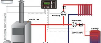
1. Thermostat temperature sensing bottle 2. Piezo igniter 3. Bracket 4. Control handle 5. SIT thermocouple temperature sensing element 6. Pilot burner 7. Spark electrode 8. Valve inlet 9. Valve outlet 10. SIT thermocouple 11. Modeling thermostat 12. Gas valve Eurosit 630 13. High voltage cable HV 14. Traction sensor 15. Magnetic block
4.2.1 Strengthen the gas valve, item 12 (Fig. 4) of the automation, according to the layout drawing of the gas apparatus. 4.2.2 Install the piezo igniter step 2 (Fig. 4), according to the layout drawing of the gas apparatus.
4.2.3 Strengthen the bracket p.Z (Fig. 4), the pilot burner fastenings p. 6 (Fig. 4), the spark wire p. 7 (Fig. 4), and the temperature-sensitive element p. Z (Fig. 4), thermocouple SIT clause 10 (Fig. 4), according to the layout drawing of the gas apparatus.
Note: Pilot burner kit and piezo ignition kit are supplied separately.
4.2.4 Connect the main gas pipeline to the inlet of item 8 (Fig. 4), using fasteners of our own design. 4.2.5 Connect the pipeline to the outlet of item 9 (Fig. 4) and to the main gas burner using proprietary fasteners. Note: Plug unused inlet and outlet holes with a screw plug.
4.2.6 Install and secure with installation nuts on the bracket item 3 (Fig. 4) the pilot burner item 6 (Fig. 4), the spark electrode item 7 (Fig. 4) and the heat-sensitive element item 3 (Fig. 4) thermocouples SIT item 10 (Fig. 4)
4.2.7 Connect the pipeline to the installed pilot burner and to the inlet of point 11 (Fig. 3) of the gas valve.
4.2.8 Connect the SIT thermocouple item 10 (Fig. 4) to the hole item 12 (Fig. 3).
4.2.9 Connect the high-voltage cable item 13 (Fig. 4) to the spark electrode item 7 (Fig. 4) and the piezo igniter item 2 (Fig. 4).
4.2.10 Install and secure the temperature-sensitive thermostat cylinder, item 1, in the upper part of the water casing of the boiler (Fig. 4).
ATTENTION: AFTER INSTALLING AND MOUNTING THE AUTOMATION, CHECK THE TIGHTNESS OF ALL CONNECTIONS
IV. Eurosit 630 automation operation, setup and adjustment
The principle of operation of the automation is based on the electromechanical operation of the temperature-sensitive elements of the SIT thermocouple item 10 (Fig. 4) and the modeling thermostat item 11 (Fig. 4) 5.1 Starting gas burner devices. 5.1.1 Ignition of the pilot (ignition) burner: the initial position of the round control handle item 4 (Fig. 4) is in the “off” position 5.1.1.1 Turn control handle 4 counterclockwise to the ignition position 5.1.1.2 Press control handle 4 all the way , and do not release it, press the piezo ignition button. 5.1.1.3 Do not release control handle 4 for 5-10 seconds. 5.1.1.4 Release the control handle and check the presence of flame on the pilot burner step 6 (Fig. 4).
5.1.1.5 If there is no flame, repeat step 5.1.1.1.;
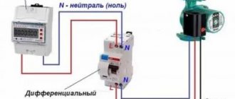
5.1.1.2.; 5.1.1.Z., increasing the time of pressing control handle 4. 5.1.2 Ignition of the main gas burner. 5.1.2.1 To turn on the main gas burner, turn control knob 4 counterclockwise to position 1-7. The maximum coolant temperature of 90°C corresponds to number 7 on the control handle. 5.2 Switching off the main and pilot (pilot) burners. 5.2.1 To turn off the main gas burner, turn control knob 4 clockwise to position. At the same time, a torch will burn on the pilot burner. 5.2.2 To completely shut off the gas supply to the pilot and main gas burner, turn the control knob clockwise to the “off” position 5.3 Adjusting the coolant temperature. 5.3.1 The coolant temperature is adjusted by a thermostat through a temperature-sensitive cylinder installed on the top of the boiler water casing. 5.3.2 When the coolant reaches the set temperature, the thermostat automatically shuts off the gas supply to the main burner. 5.3.3 When the coolant temperature drops, the thermostat opens the gas supply to the main burner. Ignition of the gas occurs from the torch of the pilot (ignition) burner. 5.4 Protection of gas burning devices. 5.4.1 Protection in case of sudden gas shutdown. 5.4.1.1 If the gas is suddenly turned off or the flame of the pilot and main burner is blown out, heating of the temperature-sensitive element of the SIT thermocouple stops; decreasing e.m.f. The thermocouple will turn off the magnetic block in step 10 (Fig. 3) and the valve of the magnetic block will shut off the gas supply. 5.4.1.2 Without restarting the gas burner manually, gas supply to the main burner is impossible. 5.4.2 Protection in the absence of traction. To protect gas burner units in the absence of draft, a draft sensor can be connected to the gas valve. The traction sensor is a thermal relay that opens the contacts when the temperature exceeds a preset one. In the absence of traction, the thermal relay item 14 (Fig. 4), placed in the upper part of the combustion chamber, overheats and opens the circuit connecting the thermocouple item 10 (Fig. 4) to the gas connector item 12 (Fig. 4). In this case, the magnetic block step 15 (Fig. 4) will shut off the gas supply. 5.5 Adjustment and setup. ATTENTION : all adjustment and commissioning work must be performed based on the specific characteristics of the automation.
5.5.1 Check the gas inlet and outlet pressure using test points 6 and 7 (Fig. 2). To do this, unscrew the screw plugs and connect the control devices. After checking, install the screw plugs and check their tightness. Recommended torque 2.5 Mt.
5.5.2 Adjustment of the maximum and minimum gas output flow. These adjustments must be made when the temperature sensitive cylinder step 1 (Fig. 4) is cold. 5.5.2.1 Adjusting the maximum gas flow: · turn control knob 4 to position 7; · turning the adjusting screw of the gas pressure regulator, item 13 (Fig. 1) clockwise, increasing the gas flow. 5.5.2.2 Adjusting the minimum flow: · starting from step 7, slowly rotate the control knob clockwise until the torch on the main burner is about to go out; · rotate the minimum gas flow screw No. 3 (Fig. 1) counterclockwise to increase the gas flow. Required adjustment conditions:
· flame extinction or flame backstroke is absolutely impossible at minimum and maximum gas output flow. 5.5.3 Adjusting the gas flow into the pilot (ignition) burner: · rotating the screw in step 5 (Fig. 1) clockwise, reducing the gas flow and, accordingly, vice versa. Mandatory adjustment conditions: the pilot burner flame must cover and constantly heat the temperature-sensitive element of the SIT thermocouple.
dobrahata.in.ua
Automatic 630 EUROSIT. Adjustment.
Today, the Rostov Boiler Equipment Plant CJSC Rostovgazoapparat produces Siberia boilers, widely known in our country. The author of these lines had the honor of installing such a boiler in his own home. Everything would be fine, but in severe frosts problems with the insufficient power of this device began to appear. At first, I was guilty of power, since the area of the heated house is 95 square meters. m. and the declared boiler power is 11.6 kW. Naturally, the power reserve is small, since the recommended reserve should be + 30% of the area of the house. My boiler must be at least 12.5 kW. that is, for heating 125 sq.m. Now a brief background for buyers of Siberia boilers.
WARNING
Some versions of the multifunction gas regulator are supplied without certain parts.
Therefore, when installing regulators, it is necessary to check the presence of the following components: • minimum gas flow adjustment screw 3
(
Fig. A
) • maximum gas flow adjustment screw
2
(
Fig. A
) or, optionally, pressure regulator
2'
(
Fig. A*
) If not, perform installation as follows: • check that the accessory code is correct • insert the minimum gas flow adjustment screw into hole
14
(
Fig. B
), the maximum gas flow adjustment screw or pressure regulator into hole
15
(
Fig. B
) • insert the accessories and wrap completely.
Tightening torques: - adjustment screws 7Nm - pressure regulator: 1Nm Gas connection
Use a gas pipe with Rp 3/8 ISO 7 thread. Tightening torque: 25 Nm.
It is possible to connect a tube diameter of 12 mm using an o-ring and a nut (codes 0.958.025 and 0.957.007). Tightening torque 15 Nm. The valve has two inlet ports 10
and
12
(
Figure D
) and two outlet ports
11
and
13
(
Figure D
).
Holes that have not been used must be closed with plugs (code 0.972.058). Tightening torque 7 Nm. Connecting the pilot burner
pin
8
(
Fig. D
) Tubes with diameters of 4 mm, 6 mm or 1/4? can be used.
Use nuts and o-rings of the appropriate size. Tightening torque 7 Nm. ATTENTION
After completing the work, check the connections for leaks.
Setting the maximum and minimum gas flow
These settings are made with a cold bulb.
Setting the maximum gas flow
(version without pressure regulator) - (
Fig. A
).
Turn control knob 4
to position
7
.
Fully tighten the adjustment screw 2
, and then gradually turn it out until the required gas flow is achieved.
WARNING
Once fully tightened, do not back out the screw more than
two
turns.
Disabling the maximum gas flow function
Fully tighten the adjustment screw
2
, and then turn it out two turns and lock it.
Disabling can also be done by replacing adjustment screw 2
with a plug (code 0.972.057). In this case, the plug must be completely screwed in.
Setting the maximum gas flow
(version with pressure regulator) - (
fig. A*
).
Turn the control knob to position 7
.
When turning the adjustment screw 2' clockwise (VERSION WITH PRESSURE REGULATOR)
, the gas flow increases.
Disabling the pressure regulator function
2'
adjustment screw fully clockwise.
Setting the minimum gas flow
Slowly turn the control knob clockwise to the minimum power position (close to the main burner off position).
When turning adjustment screw 3
counterclockwise, the gas flow increases. It is also possible to use screws with calibrated holes (optional) instead of screws for adjusting the maximum and minimum gas flow. In this case, the screws must be tightened with a tightening torque of 7 Nm.
Setting the gas supply to the pilot burner
When screw
5
clockwise, gas consumption decreases.
ATTENTION
After completing all adjustments and adjustments, check the tightness of the seals and the correct operation of the equipment. Flame separation or breakthrough is strictly prohibited at the corresponding maximum and minimum gas pressure. After completing the adjustment work, secure the seals and/or adjustment screws with paint.
I present questions and answers from the old site; if you don’t find anything useful for yourself, write below in the comments.