Water heating systems
Water heating is a method of heating rooms using a liquid coolant (water or water-based antifreeze).
Heat is transferred to the premises using heating devices (radiators, convectors, pipe registers, etc.). Unlike steam heating, water is in a liquid state, which means it has a lower temperature. This makes water heating safer. Radiators for water heating have larger dimensions than for steam heating. In addition, when heat is transferred over a long distance using water, the temperature drops significantly. Therefore, they often make a combined heating system: from the boiler room, with the help of steam, heat enters the building, where it heats the water in a heat exchanger, which is already supplied to the radiators.
In water heating systems, water circulation can be either natural or artificial. Systems with natural circulation of water are simple and relatively reliable, but have low efficiency (this depends on the correct design of the system).
A disadvantage of water heating is also air pockets, which can form after draining the water during heating repairs and after severe cold snaps, when the temperature in the boiler rooms is increased and part of the air dissolved in it is released from it. To combat them, special release valves are installed. Before the start of the heating season, air is released using these valves due to excess water pressure.
Heating systems are distinguished according to many characteristics, for example: - according to the method of wiring - with upper, lower, combined, horizontal, vertical wiring; - according to the design of the risers - single-pipe and double-pipe;
— along the flow of the coolant in the main pipelines — dead-end and associated; - according to hydraulic modes - with constant and variable hydraulic modes; - according to the communication with the atmosphere - open and closed.
About types of pumps and their power supply
For domestic heating systems, pumps with an energy consumption of 60-100 watts are used. This is comparable to a regular light bulb. Why is energy consumption so low? The fact is that the circulation pump does not lift water , but only helps it overcome local resistance in heating systems.
Simply put, a circulation pump can be compared to a ship's propeller. The propeller ensures the movement of the ship by pushing the water, but the water in the ocean does not decrease and balance is maintained. However, there is a downside here. If there is a long power outage, the home owner may be in for an extremely unpleasant surprise. Overheating of the coolant can cause destruction of the circuit, and stopping circulation will lead to subsequent defrosting.
Therefore, during a power outage, it must remain possible for the system to operate under natural circulation conditions. To do this, it is necessary to minimize all possible turns and bends in the circuit , and it is also important to use modern ball valves as shut-off valves. Unlike their screw counterparts, they provide minimal resistance to fluid flow when open.
Two types of pumps can be included in the heating system circuit:
- circular;
- promotions.
The circulation pump pushes water, and no matter how much it pushes it out, the same amount of water will flow to it from the other side. Fears that the pump may push coolant through an open expander are unfounded. Heating systems have a closed circuit and the amount of water in them is always the same.
Central heating systems can also include booster pumps , which would be more correctly called pumps, since they raise water by increasing pressure. Let's use an analogy with a fan. No matter how much a regular fan moves air around the apartment, the amount of air will not change. Only a light breeze and air circulation are formed. Atmospheric pressure will remain the same.
Heating systems with natural water circulation
These are one of the simplest and most common heating systems for small houses and apartments with individual heating. Disadvantages of heating systems with natural circulation of water: - small radius of action (up to 30 m horizontally), which is the result of low circulation pressure; — slow activation due to the high heat capacity of water and low natural circulation pressure; — increased risk of water freezing in the expansion tank if it is mounted in an unheated room.
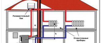
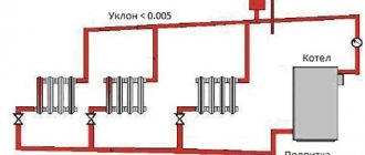
The schematic diagram of a heating system with natural circulation consists of a boiler (water heater), supply and return pipelines, heating devices and an expansion tank. The water heated in the boiler flows through the supply pipeline and risers into the heating devices, gives them part of its heat, then returns through the return pipeline to the boiler, where it is again heated to the required temperature, and then the cycle is repeated.
Rice. 1. Schematic diagram of a water heating system with natural water circulation
All horizontal pipelines of the system are made with an inclination in the direction of water movement: the heated water, rising up the riser due to thermal expansion and squeezing out the return pipeline by colder water, spreads along the horizontal outlets by gravity, and the cooled water also flows back into the boiler by gravity. The slopes of the pipelines also contribute to the removal of air bubbles from the pipes to the expansion tank: gas is lighter than water, so it tends upward, and the inclined sections of the pipelines help it not to linger anywhere and enter the expander, and then into the atmosphere. The expansion tank creates constant pressure in the system, receives a volume of water that increases when heated, and when cooled, releases the water back into the pipeline.
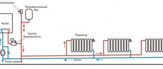
Water in the heating system rises due to expansion when heated and under the influence of gravitational pressure; movement (circulation) occurs due to the difference in the densities of heated (rising through the supply riser) and cooled water (descending through the return riser). Gravitational pressure is used to move the coolant and overcome resistance in the pipeline network. These resistances are caused by the friction of water against the walls of the pipes, as well as the presence of local resistances in the system. Local resistances include: branches and turns of pipelines, fittings and the heating devices themselves. The more resistance there is in the pipeline, the greater the gravitational pressure must be. To reduce friction, pipes of increased diameters are used.
The circulation pressure Pc = h (ρо-ρg) depends (Fig. 1): - on the difference in elevations of the center of the boiler and the center of the lower heating device h, the greater the difference in heights between the centers of the boiler and the device, the better the coolant will circulate; - on the density of hot water ρg and chilled water ρo.
How does circulation pressure appear? Let's imagine that in the boiler and heating radiators, the temperature of the coolant changes abruptly along the central axes of these devices, which, by the way, is not far from the truth. That is, there is hot water in the upper parts of the boiler and radiators, and cooled water in the lower parts. Hot water has less density, and therefore less weight, than cooled water. Let's mentally cut off the upper part of the heating circuit (Fig. 2) and leave only the lower part. So what do we see? And the fact that we are dealing with two communicating vessels, which is well known to us from school physics. The top of one vessel is higher than the top of the other; Under the influence of gravity, water tends to move from the upper vessel to the lower one. The heating circuit is a closed system; the water in it does not splash out, as in communicating vessels, but tends to “calm down” (occupy one level). Thus, a high column of cooled heavy water after the radiators constantly pushes a low column of water in front of the boiler and pushes hot water, that is, natural circulation occurs. In other words, the higher the center of the radiators is relative to the center of the boiler, the greater the circulation pressure. The installation height is the first indicator of pressure. Slopes of the supply pipelines towards the radiators and the return line from the radiators to the boiler only contribute to this process, helping the water overcome local resistance in the pipes.
Rice. 2. Graphic diagram of the occurrence of circulation pressure
Therefore, in private homes it is best to place the boiler below the heating devices, for example, in the basement. The second indicator on which the circulation pressure depends is the difference between the densities of chilled and hot water. Systems with natural coolant circulation are self-regulating systems. When carrying out qualitative regulation, that is, when the water heating temperature changes, quantitative changes spontaneously occur - the water flow changes. Due to changes in the density of hot water, the natural circulation pressure will increase (decrease), and therefore the amount of circulating water. That is, when it’s cold outside, it becomes colder in the house and turning on the boiler at full power, we increase the heating of the water, noticeably reducing its density. Having entered the heating devices, the water gives off heat to the cooled air in the room, and its density increases further. Looking at the part of the formula in parentheses, we see that the greater the difference between the densities of chilled and hot water, the greater the circulation pressure. Consequently, the more the water is heated in the boiler and the more it cools in the radiator, the faster it circulates through the heating system and this happens until the air in the room warms up. After this, the water begins to cool in the radiators more slowly, its density is no longer much different from the density of the water leaving the boiler, and the circulation pressure begins to gradually decrease. But as soon as the temperature in the room begins to decrease, the circulation pressure will begin to increase and the speed of water circulation in the pipes will increase, supplying more heat to the radiators and increasing the air temperature. This is how the system self-regulates - the simultaneous change in temperature and amount of water ensures the necessary heat transfer from heating devices to maintain the temperature of the premises.
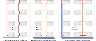
Water heating systems with natural circulation are two-pipe with upper and lower wiring, as well as single-pipe with upper wiring.
Choosing a wiring diagram for systems with natural circulation
There are a huge variety of schemes according to which natural regulation can be implemented. But they all fall into 2 categories:
- Single-pipe
- Two-pipe
Two-pipe scheme
Despite the more complex installation process, it is the two-pipe heating scheme with natural coolant circulation that has become widespread. The liquid is transported through two pipes: one is laid at the top and heated water flows through it, the second at the bottom and cooled water flows.
To build a simple two-pipe circuit yourself, you can follow the following instructions:
- First, select the location where the storage unit will be located.
- An expansion tank is installed above the boiler; together they are connected by a vertical pipe, which is wrapped in heat-insulating material
- At the 1/3 level of the expansion barrel, the top pipe is cut in to transport the heated coolant
- Having measured the distance from the floor to the highest point, it is necessary to make a cut into the wiring at a height of approximately 2/3
- Closer to the top of the expansion tank, a second pipe is inserted - an overflow pipe, through which excess will be removed into the sewer system
- Then you need to run pipes to the radiators
- The batteries are connected to the lower water supply, which should be laid parallel to the upper one
It is necessary to try to position the pipes as accurately as possible in a heating system with natural circulation and ensure an optimal height difference between the radiators and the boiler. The latter should be located below the batteries, so preference is given to floor-standing devices that are placed in a special recess or basement.
The attic space will have to be insulated. If it is too cold, the liquid in the pipes may freeze.
Let's consider a few more rules that should be followed:
- It is recommended to run the top pipe with a slight slope - 6-7 degrees
- If possible, the boiler is installed significantly lower than the heating devices
- You need to choose pipes made of metal-plastic or polymer-based with an internal diameter of 32 mm
There is no need to balance two-pipe heating if the pipes are selected correctly. Nevertheless, it is mandatory to install chokes on the connections to each battery. It is also worth noting the high initial costs of laying two circuits at once and the length of time spent on the work.
Single-pipe scheme
To reduce installation costs, choose the option of laying just one pipe. In this case, a cyclic closed loop is obtained that meets the following conditions:
- Radiators should cut parallel to the main ring, and not break it at certain points
- It is necessary to provide an air vent for each battery. This solution will provide the opportunity to bleed air in one specific area
- To equalize the temperature, it is recommended to install thermal heads and chokes
A closed single-pipe heating system with natural circulation is popular. In a particular case, it will be possible to neglect the expansion tank, completely isolating the coolant.
What affects the speed of circulation?
If in a forced system the rate of coolant circulation through the pipes depends on the performance of the pump, here things are different. To increase it, you must adhere to a number of rules:
- It is necessary to optimally select shut-off valves and monitor transitions in pipe diameters
- Various turns can become an insurmountable obstacle, so their number is reduced to a minimum, trying to make all sections straight
- The most suitable internal diameter of pipes is 32-40 mm
- The inner surface of the pipes must be perfectly smooth and not accumulate deposits; steel products should not be considered
Working system video
https://youtube.com/watch?v=Ej-3IVxqKbY
In custody
The installation of heating systems with natural circulation requires certain training, skills and knowledge. But in order to remain confident in its performance, it is worth installing a pump, which will be turned on if necessary.
2.1. Two-pipe heating systems with overhead wiring
Water from the boiler rises up through the supply pipeline and then flows through risers and connections to the heating devices (Fig. 3-5). Horizontal highways are laid with a slope. From the heating appliances, water flows through return lines and risers into the return pipeline and from there into the boiler.
Rice. 3. Scheme of a two-pipe water heating system with top wiring and natural water circulation
Rice. 4. Scheme of a two-pipe water heating system with overhead wiring and natural water circulation : 1 - boiler; 2 - main riser; 3 - supply line; 4 - hot risers; 5 — return risers; 6 - return line; 7 - expansion tank
Each heating device of this heating system (Fig. 4) is served by two pipelines - supply and return, which is why such a system is called a two-pipe system. Water is fed into the system from a water supply system, and if there is none, then water is poured manually through the opening of the expansion tank. It is better to recharge the heating system from the water supply into the return line, since cold water from the water supply will mix with the relatively hot water of the return line and increase its density, increasing the circulation pressure for the time of replenishment.
Heating systems with natural circulation are made single- and double-circuit (Fig. 5). In single-circuit systems, the boiler is installed at the beginning of the circuit, and the piping is made to the right or left of it, encircling the perimeter of the entire house or apartment, while the horizontal length of the ring should not exceed 30 m (preferably up to 20 m). The longer the ring, the greater the hydraulic resistance (friction forces inside the pipe) in it. In double-circuit systems, the boiler is placed in the center, and the piping (ring contours) is placed on both sides of the boiler; the total horizontal length of the pipes should not exceed 30 m (preferably up to 20 m). To obtain a hydraulically balanced system, the lengths of the rings of the dual-circuit system and the number of radiator sections must be made approximately the same.
Depending on the direction of movement of the coolant in the main pipelines, heating systems can be dead-end or with associated water movement.
Rice. 5. Scheme of a two-pipe heating system with overhead wiring and natural coolant circulation
In dead-end heating systems, the movement of hot water in the supply line is opposite to the movement of cooled water in the return line. In this scheme, the length of the circulation rings is not the same; the further the heating device is located from the boiler, the greater the length of the circulation ring.
In dead-end systems, it is difficult to achieve the same resistance in short and more distant circulation rings, so heating devices located close to the main riser will warm up much better than those located far from it. And with a low thermal load of the circulation rings closest to the main riser, their hydraulic connection becomes even more difficult.
In heating systems with associated movement of water, all circulation rings have a length, so risers and heating devices operate under the same conditions. In such systems, regardless of the horizontal location of the heating device in relation to the main riser, their heating will be the same. However, heating systems with associated movement of water are used to a limited extent, since often when designing real heating systems that take into account the layout of the house, it turns out that during installation a larger number of pipes will be required than for dead-end systems. Therefore, such systems are used in cases where it is impossible to link the circulation rings to each other in a dead-end system.
To expand the use of dead-end systems, the length of highways is reduced and instead of one long circuit, two short circuits or several are made. In such cases, better horizontal adjustment of the system is ensured. Balancing (hydraulic balancing) of the heating rings of the circuit begins at the design stage of the heating system. In order for it to work evenly, all rings of the circuit must have approximately the same hydraulic resistance, that is, a ring located close to the main riser must have almost the same resistance as a ring distant from the main riser, and the sum of the hydraulic resistance of all rings should not exceed the magnitude of the circulation pressure. Otherwise, there may be no coolant circulation in the system.
Important nuances of operation
As a result of using pumped water circulation, the radius of the heating system increases, and the diameters of the pipes decrease.
It becomes possible to connect to boilers with increased parameters. In order to ensure constant circulation of water, it is necessary to install at least two such devices. One will be the main one, working, and the other will be the backup one. In a heating system, such a pump is constantly filled with water and experiences hydrostatic pressure on both sides - from the suction and discharge (outlet) pipes.
Pumps made with water-lubricated bearings can still be placed on the supply and return lines. However, their most common use can be found on the return line. Although this happens more out of habit, because previously it made sense to install the circulation pump on the return line because when placed in colder water, the service life of the bearings increased. Now, judging objectively, the installation location is not significant.
However, to prevent air locks from leaving the bearings without cooling and lubrication, the motor shaft must be positioned strictly horizontally. Yes, the design of the device is such that the rotor and shaft with bearings must be continuously cooled so that an unexpected malfunction does not occur. On the body of this equipment there is usually an arrow indicating the direction in which the coolant in the system should move.
Sump
It is highly desirable, but not necessary, to install a sump tank in front of the pump. The function of this equipment is to filter out the inevitable sand and other abrasive particles. They can destroy the impeller and bearings. Since the insertion diameter is usually quite small , a regular coarse filter will do. The barrel for collecting suspended matter should be directed downwards - so even if partially filled with water, it will not interfere with its circulation. Filters also often have an arrow. If you ignore it, you will have to clean the filter much more often.
Backup power supply
When the heating system is installed on the principle of forced circulation, it makes sense to also take care of a backup power source. Usually, it is installed with the expectation that its operation will last for a couple of hours in the event of a power outage. Approximately this amount of time is usually enough for specialists to determine the cause of the emergency power outage and restore operation. To extend the operating time of the backup power source, you will need external batteries that connect to it.
Heat resistant cable
When connecting electrical equipment to the heating system, it is necessary to exclude the possibility of moisture or condensation getting into the terminal box. If the coolant heats up in the heating system by more than 90 degrees, then a heat-resistant cable is used. Contact of the cable with the pipe walls, pump housing, or motor is under no circumstances allowed. A cable is connected to the terminal box on the left or right side. In this case, the plug is rearranged. If the terminal box is located on the side, then the cable is supplied exclusively from below. In this case, a natural safety measure is to ensure grounding.
Bypass
A popular scheme is to install a circular pump on a bypass, which is cut off from the main system using two taps. Such an installation can help to repair or replace the device without damaging the entire heating system of the house. In the off-season, everything can function without a pump, which is shut off using the same valves. With the arrival of frost, his work resumes. It is enough to open the shut-off valves at the edges and close the ball valve located on the main circuit.
2.2. Two-pipe heating systems with bottom wiring
Rice. 6. Scheme of a two-pipe water heating system with bottom wiring and natural coolant circulation
It differs from a system with top wiring in that the supply pipeline is laid from below next to the return one (Fig. 6) and the water moves from bottom to top through the supply risers. Having passed through the heating devices, the water flows through the return lines and risers into the return line and from it into the boiler. Air is removed from the system through air bleeders (Mayevsky taps), installed on all heating devices, or using automatic air vents installed on risers or special air lines. Heating systems with bottom wiring, as well as with top wiring, can be designed with one or more circuits, with dead-end and associated movement of the coolant (Fig. 7) in the supply and return lines.
Rice. 7. Examples of diagrams of two-pipe heating systems with natural circulation of water and lower distribution of the supply pipeline
Systems with bottom wiring and natural coolant circulation are used extremely rarely because they have a large number of end radiators that require the installation of air bleeders. And since these systems have expansion tanks that communicate with the atmosphere and draw air into the circulation ring, the procedure for bleeding air from radiators becomes almost weekly. To eliminate this drawback, the hot water supply pipelines are looped with so-called air pipelines, which collect air and discharge it into the expansion tank above the water standing in it (Fig. 8-9).
Rice. 8. Scheme of a two-pipe heating system with bottom wiring, air outlet line and natural circulation
Rice. 9. Diagram of a two-pipe heating system with bottom wiring, air outlet line and natural circulation : 1 - boiler; 2 - overhead line; 3 – lower wiring; 4 - supply risers; 5 — return risers; 6 - return line; 7 - expansion tank
Such systems are used even less frequently because they resemble overhead systems and require almost the same number of pipes. In general, the advantage of their use is lost: pipe risers penetrate rooms from floor to ceiling, and the whole point of lower wiring of the heating system was that with it, risers disappeared in the rooms (at least on the top floor).
Manufacturer's choice
In this important matter, it is still worth paying attention to those companies that have been operating in this market for a long time and have a strong reputation. Experts advise paying attention to brands such as WILO , DAB , Pedrollo and others. As a rule, fully automated assembly takes place at manufacturing plants, which guarantees product quality. Many models have an electronically commutated motor and a built-in power regulator that monitors the water circulation in the system and the ambient temperature. It can be used to make additional adjustments. In addition, it should be noted that many modern pumps are connected to the automation of the heating boiler, which avoids unnecessary losses.
2.3. Single-pipe natural circulation heating systems
Rice. 10. Single-pipe heating system with overhead wiring and natural circulation of water (above) and designs of radiator units (below)
Single-pipe systems with natural coolant circulation are made only with an upper distribution of the supply pipeline, in which there are no return risers (Fig. 10). Compared to two-pipe systems, single-pipe systems are easier to install, require fewer pipes and look more beautiful.
Single-pipe heating systems are divided into two types.
According to one scheme - flow-through, there is no supply riser as such, and the radiators along the height of the house are connected in series to each other. Hot supply water flows sequentially, from top to bottom, through all radiators, starting from the top, and enters the radiators of the lower floors cooled. Therefore, it is hot on the upper floors and cold on the lower floors. In order to somehow balance the heating circuit, radiators with a large number of sections are installed in the lower floors. In a flow-through system, it is impossible to install control valves, since when the valve at one or another radiator is reduced or closed, the entire riser is partially or completely closed.
With this scheme, it is impossible to regulate the air temperature in the rooms. If the house is two-story, then it is impossible to start the heating system on only one floor. Flow-through heating schemes were very popular in the mid-twentieth century, when the main goal was to save pipes. Currently, it is almost never used.
In another scheme with closing sections (bypasses), shown in Fig. 11, from the riser, part of the water flows into the upper radiators, and the rest of the water is directed through the riser to the radiators located below. The water in such a system cools a little less, which means the difference between temperatures on the upper and lower floors is smaller. In fact, this is an improved flow circuit in which a closing section is made between the radiator connection pipes - a bypass.
Rice. 11. Connection diagrams for heating devices in one-pipe and two-pipe heating systems
The diameter of the pipe of the closing section is made one size smaller than the diameter of the radiator connection pipes. As a result, the coolant entering from above is divided into two flows: one part enters the radiator, the other through the bypass to the lower radiators. If the diameter of the bypass is made the same as the pipes for connecting the radiator, then the coolant in the radiator will stop circulating, since the hydraulic resistance in the radiator will be greater than in the bypass. After all, water always flows where there is less hydraulic resistance.
When installing a bypass with a diameter equal to the diameters of the radiator connection pipes to balance the heating system, the amount of water entering the device is regulated by valves that are installed on the connection pipe and the bypass. Thus, by closing (opening) the valves on the supply pipe connecting the radiators or bypass, you can regulate the flow of coolant into the radiator or riser. For example, you can completely turn off the radiator and redirect all the coolant to the bypass and then to the lower radiators on the riser, or, conversely, close the bypass and direct the entire heat flow to the radiator.
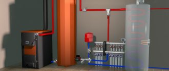
Rice. 12. Diagram of the heating and hot water supply system of the house
In modern heating systems, the two valves installed on the supply pipe and bypass are replaced by one, called a three-way valve. Depending on the position of the closing damper, the three-way valve simultaneously opens the path for coolant into the radiator and closes the flow into the bypass, or, conversely, closes the bypass and opens the path to the radiator. Such cranes can be equipped with an electric drive connected to a special device - a controller. The controller measures the air temperature in the room or the temperature of the coolant and sends a command to a three-way valve, which increases or decreases the supply of coolant to the radiator, and discharges the rest of the coolant into the bypass.
As in systems with two-pipe wiring, in a single-pipe system it is possible to ensure dead-end and parallel movement of the coolant in the return line. With parallel movement, all rings of the heating circuit become the same length and the system can be balanced. With dead-end movement, it is very difficult to balance the temperature of the coolant, since the imbalance occurs not only along the length of the rings, but also along the height of the risers, which differs from two-pipe systems, where the temperature was unbalanced only along the rings.
Types and selection rules
All circulation pumps, regardless of type, operate on the following principle.
- In the inner chamber of such a device, a paddle wheel, also called an impeller, rotates.
- When there is no liquid between the two nearest impeller blades, which form the walls of the temporary working chamber, an area of rarefied air is created, which facilitates the flow of coolant into the chamber when it is located opposite the suction line.
- With further rotation of the impeller and temporary working chamber, the coolant liquid contained in the latter is thrown under the influence of centrifugal force towards the walls of the inner chamber of the water pump itself. Thus, increased pressure is created in the temporary chamber, which leads to the ejection of liquid through the discharge pipe.
According to their design, circulation pumps are divided into two large categories:
- devices with a “wet” rotor;
- pumps with a “dry” rotor.
Design of a circulation pump with a wet rotor
Devices of the first type, the rotor parts of which are in constant contact with the pumped medium, are distinguished by their compact size and almost silent operation. Meanwhile, pumps with a “wet” rotor, which simply cut into the pipeline, are not characterized by very high efficiency.
Circulation pumps with a dry rotor are more massive and make quite a lot of noise during operation, but are characterized by high efficiency. Pumps of this type are installed, the rotor of which is isolated from contact with the pumped medium, using a cantilever mounting to the wall.
Glandless pump design
To ensure high efficiency of the water pump, when choosing it, it is necessary to proceed from the characteristics of both the equipment itself and the heating systems on which it is planned to be used. Parameters that require special attention are the performance of the pump and the amount of pressure it creates.
- Productivity characterizes the amount of liquid that the device is capable of pumping per unit of time. This parameter is measured in m3/hour. It is advisable to opt for water circulation pumps, which are able to pump the entire volume of water in the system three times in an hour.
- The units for measuring the pressure created by a water pump are meters or decimeters of water column.
Table 1. Average pump selection parameters. Can be used as a guide when choosing the right model
For long-distance heating systems, more powerful water pumps should be purchased, which will ensure rapid filling of the pipes and efficient circulation of the coolant.
When choosing a circulation pump based on power, you must first calculate the total resistance of all hydraulic components and focus on the obtained value. The cross-section of the inlet and outlet pipes of the water pump for heating is also important: its size should be one division less than the diameter of the pipes that make up the heating system.
Water heating systems with pump circulation
In a heating system with forced (pump) circulation, the same connection diagrams are used as in a heating system with natural circulation, but due to the inability to comply with all slopes or the length of the line is too long, a circulation pump is connected to ensure constant circulation of the coolant in a closed heating system (Fig. 13-9-15).
Rice. 13. Scheme of an open two-pipe water heating system with overhead wiring with forced circulation : 1 - boiler; 2 - main riser; 3 - supply line; 4 — supply riser; 5 - radiator; 6 — return riser; 7 - return line; 8 - circulation pump; 9 — double adjustment valve; 10 - expansion pipe; 11 — expansion tank; 12 — overflow pipe; 13 — air collector
Rice. 14. Scheme of a closed water heating system with forced circulation: The pump is connected to the return line, which contributes to longer operation of the heating system as a whole.
In the heating system shown in Fig. 15, all radiators on each floor are connected to a common line. Its advantages are ease of installation, lower pipe consumption and the absence of risers for each radiator, and the disadvantage is the formation of air jams due to the presence of parallel pipelines (this can be eliminated by installing air bleed valves).
Rice. 15. Scheme of a single-pipe heating system with a horizontal flow system : 1 - boiler; 2 - main riser; 3 - expansion tank; 4 - expansion pipe; 5 - circulation pump
The use of a circulation pump allows the use of longer lines, which is very important when heating multi-storey buildings. The only disadvantage of using a circulation pump is that an uninterrupted power supply is required.
Maintaining a given temperature in a room heated by a water heating system is possible in several ways: by changing the temperature, the coolant flow through the radiator, and both at the same time. The temperature of the coolant supplied to the radiators is usually regulated centrally at the heating point. To individually regulate the room temperature, radiators are equipped with control valves (manual adjustment) or thermostats (automatic adjustment).
Individual adjustment is possible with both a two-pipe and a single-pipe system; in the latter case, a bypass must be installed in front of the tap or thermostat.
Installation
After the first calculations have been made, the boiler has been installed and the pipes have been laid, the circulation pump of the required power and pressure should be correctly installed. Previously, the pump was usually installed on the return pipeline: the bearings wore out less and the service life increased. Still, the water here is 20 degrees colder. Now there are many good pumps that can be safely installed on the supply pipe.
You just need to remember one thing.
The expansion tank in any closed hydraulic system is like a starting point. Before it, creating compression, the pump pumps water, after it, on the contrary, it dilutes it. It would seem that there should not be any special problems. If not for one “but” related to the statistical pressure of the tank. When water is injected, the pressure increases, and in the opposite case, it decreases, which can lead to both boiling of the coolant and the release of air. To prevent this from happening, four rules must be followed.
- Raising the tank to the proper height (at least a meter). It all depends on the height of the room and insulation may be required.
- The tank can be placed at the extreme point to turn on the upper line. This method is more suitable for reconstruction.
- The expansion tank is connected in close proximity to the circulation pump pipe.
- The pump is connected directly to the supply line near the tank connection point. True, here you will need to choose a model from the best manufacturers.
True, in recent years, not only open but also closed type tanks have appeared on the market, the so-called “expanzomats”, which are distinguished by their high operational reliability and safety. Inside they are divided into two parts by a membrane. The air half contains a nitrogen-containing mixture. Therefore, even at maximum pressure, nothing will happen, only the safety valve will open and water will be discharged. These tanks can be installed almost anywhere, but it is best next to the boiler, along with the expander, where the most convenient place is located.
Connection diagrams for heating devices
Rice. 16. Some diagrams for connecting heating devices
Rice. 17. Wiring for radiators of the heating system
Rice. 18. Wiring diagram for a cast iron radiator
Rice. 19. Installation diagram of cast iron radiators
Circulation pump in a gas boiler
The circulation pump in the design of a gas boiler accelerates the coolant through the heating system, due to which the coolant cools in the system more slowly and returns to the boiler in a “heated” form. Since heating in the boiler occurs to a certain temperature, the next heating cycle of the coolant will be shorter. This results in lower gas consumption and faster water heating cycles (higher efficiency).
It is believed that hydraulic heating systems do not require the installation of circulation pumps, however, it will not interfere at all in old heating systems with large diameter pipes.
By purchasing a gas boiler with a circulation pump in the design, you no longer need to install a separate circulation pump in the heating system.